
Audio Circuit
Index 27
TRIODE_COMMON_PLATE_MIXER
Published:2009/7/23 23:43:00 Author:Jessie
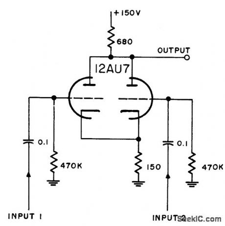
Is good adder for coincident inputs. Proves unity gain. Generally preferred to pentode common-plate mixers.-NBS, Handbook Preferred Circuits Navy Aeronautical Electronic Equipment, Vol. 1, Electron Tube Circuits, 1963, p N4-8. (View)
View full Circuit Diagram | Comments | Reading(969)
RANGE_STROBE_MARKER_IFF_MIXER
Published:2009/7/23 23:55:00 Author:Jessie
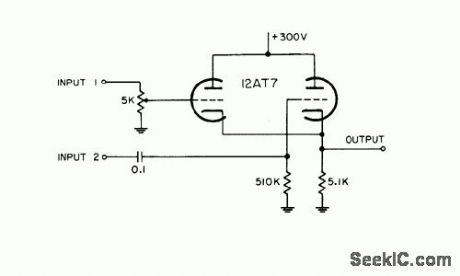
Combines positive-polarity markers with iff signals, to give 8-v positive output.-NBS, Handbook Preferred Circuits Navy Aeronautical Electronic Equipment, Vol. 1, Electron Tube Circuits, 1963, p N4-2. (View)
View full Circuit Diagram | Comments | Reading(918)
F_M_MODULATOR_FOR_TAPE_RECORDER
Published:2009/7/24 4:51:00 Author:Jessie
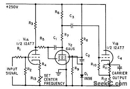
Miller-effect transitron oscillator V2 generates 7.5-kc carrier that is frequency-modulated by low-frequency action potentials from nerve fibers, to permit recording on ordinary tape recorder.-K. D. Broadfoot, F-M Magnetic Tape System Records Low-Frequency Nerve. Fiber Potentials, Electronics, 34:28, p 66-67. (View)
View full Circuit Diagram | Comments | Reading(869)
AUDIBLE_VOLTMETER
Published:2009/7/3 2:17:00 Author:May
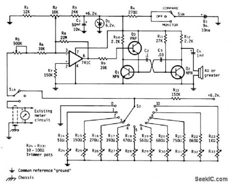
Voltage-controlled audio oscillator produces 400-Hz tone for 0 V, with frequency of tone increasing with voltage overtwo-octave rangeto 1600 Hz for maximum or full-scale voltage. Ten-resistor voltage divider produces calibrated reference tones corresponding to main 0-10 divisions of meter scale foraural comparison. Simple square-wave audio oscillator Q1-Q2 is voltage-controlled by Q3, which in turn is driven by opamp whose gain is set by R5. Article covers adjustment of sensitivity pot R5, and frequency pots R24-R33 so VCO tracks voltage being measured and tones coincide at MONITOR and COMPARE positions of S1 for each meter division.-H. F. Batie, An Audible Meter for the Blind Amateur, CQ, Dec. 1973, p 26-31. (View)
View full Circuit Diagram | Comments | Reading(3)
LOW_DISTORTION_INPUT_SELECTOR_FOR_AUDIO_USE
Published:2009/7/2 4:23:00 Author:May
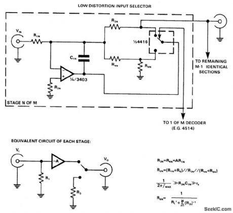
CMOS switches are used directly to select inputs in audio circuits, this can introduce unacceptable levels of distortion, but if the switch is included in the feedback network of an op amp, the distortion due to the switch can be almost eliminated. The circuit uses a 4416 CMOS switch, arranged as two independent SPDT switches. If switching transients are unimportant, R5 and C1 can be omitted, and R4 can be shorted out. However, a feedback path must be maintained, even when a channel is switched out, in order to keep the inverting input of the op amp at ground potential, and prevent excessive crosstalk between channels. (View)
View full Circuit Diagram | Comments | Reading(1184)
MICROPHONE_MIXER
Published:2009/7/2 4:20:00 Author:May
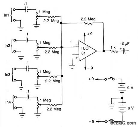
A TL081 op amp is used as a high-to-low impedance converter and signal mixer. The input impedance is approximately 1 megohm and the output impedance is about 1 kilohm. Two 9-volt batteries are used as the power source. Battery life should be several hundred hours with alkaline batteries. (View)
View full Circuit Diagram | Comments | Reading(217)
DUAL_OUTPUT_I_F
Published:2009/7/24 3:10:00 Author:Jessie
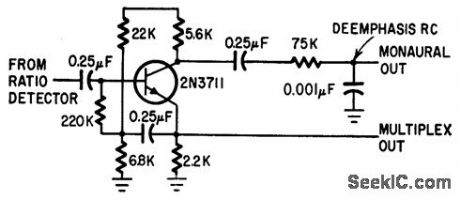
Final i-f stage of stereo f-m set has two outputs, to permit independent feed of monaural f-m.-S. Messin and T. E. Nawalinski, A Solid State Stereo Set Built in Modules, Electronics, 38:16, p 88-92 (View)
View full Circuit Diagram | Comments | Reading(824)
PREAMP_MODULE
Published:2009/7/24 3:09:00 Author:Jessie
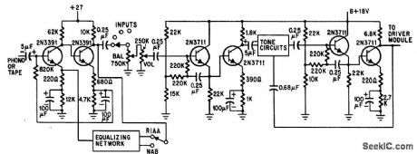
Bootstrapped emitter-followers accept high-impedance input signals and minimize loading of equalizing and tone circuits.-S. Messin and T. E. Nawalinski, A Solid State Stereo Set Built in Modules, Electronics, 38:16, p 88-92. (View)
View full Circuit Diagram | Comments | Reading(1014)
AUTOMATIC_STEREO_SWITCH
Published:2009/7/24 3:08:00 Author:Jessie
Switches f-m tuner info stereo mode and turns on indicator lamp when f-m tuner is tuned to station broadcasting stereo subcarrier or when subcarrier comes on during normal f-m broad.cast.-L. Solomon, Audio Show Features Automatic Stereo, Hi-Fi Earphones, Electronics, 34:39, p 34-35. (View)
View full Circuit Diagram | Comments | Reading(834)
AUDIO_BOOSTER
Published:2009/7/2 1:02:00 Author:May
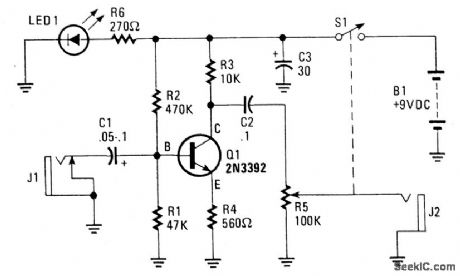
Circuit Notes
The amplifier's gain is nominally 20 dB. Its frequency response is determined primarily by the value of just a few components-primarily C1 and R1. The values of the schematic diagram provide a fesponse of ±3.0 dB from about 120 Hz to better than 20,000 Hz.Actually, the frequency response is ruler flat from about 170 Hz to well over 20,000 Hz; it's the low end that deviates from a flat frequency response. The low end's roll-off is primarily a function of capacitor C1(since RI's resistive value is fixed). If C1's value is changed to 0.1 pF, the low end's comer frequency-the frequency at which the low-end roll-off starts-is reduced to about 70 Hz. If you need an even deeper low-end roll-off, change C1 to a 1.0 pF capacitor; if it's an electrolytic type, make certain that it's installed into the circuit with the correct polarity, with the positive terminal connected to Q1's base terminal. (View)
View full Circuit Diagram | Comments | Reading(0)
SUPPRESSED_CARRIER_SIGNAL_GENERATOR
Published:2009/7/24 3:14:00 Author:Jessie
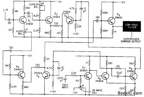
Output of 38 kc, modulated by L-R signal, is obtained by bias-modulating symmetrical stable multivibrator. Carrier will remain suppressed 46 db below maximum signal level for days.-S. Feldman, Stereo F.M Multiplex Alignment Signal Generator, Electronics, 35:3, p 37-39. (View)
View full Circuit Diagram | Comments | Reading(1141)
F_M_STEREO_MATRIXING
Published:2009/7/24 3:13:00 Author:Jessie
Matrixing is com pletely accomplished before detection. Can be substituted for 67-kc rejection filter of stereo demodulator. Also provides deemphasis.-L. Solomon, Multiplex Adaptors for Compatible F-M Stereo Reception, Electronics, 34:33, p 45-47. (View)
View full Circuit Diagram | Comments | Reading(933)
STEREO_MULTIPLEX_F_M_SIGNAL_GENERATOR
Published:2009/7/24 3:12:00 Author:Jessie
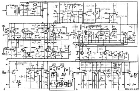
Used for testing and aligning multiplex receivers and adapters. Switches permit generating L+R or L-R separately with or without preemphasis and inserting or re moving SCA 67-kc signal.-S. Feldman, Stereo F-M Multiplex Alignment Signal Generator, Electronics, 35:3, p 37-39. (View)
View full Circuit Diagram | Comments | Reading(3283)
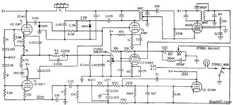
STEREO_MULTIPLEX_A_F_AMPLIFIER
Published:2009/7/24 3:10:00 Author:Jessie
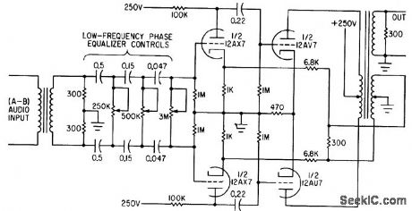
Provides low-frequency phase equalization for the A-B channel, using variable R.C high-pass filter sections that can be adjusted for cutoff between 5 and 25 cps.-Modifying an F-M Transmitter for Compatible Stereo Multiplex, Electronics, 34:28, p 60-62. (View)
View full Circuit Diagram | Comments | Reading(1481)
TWO_MESSAGES_WITH_NlXlES
Published:2009/7/1 21:16:00 Author:May
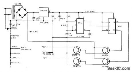
Circuit flashes two messages altemately on same Burroughs giant Nixie B7971 display. Lighted segments needed on individual Nixies to form desired wording are divided into three strings. Segments A are common to both sets of letters and numbers. Segments B are those required with A segments to form first message. Segments C are those required with A segments to form second message. Changeover from segments B to C is done with switching transistors controlled by 555 timer and 7476 or 7473 flipflop. Decimal or other punctuation is formed with NE2 ndon and 100K resistor wired in series between pin 13 of a Nixie and B or C. Article gives construction details.-J. Grimes, Put Your Name in Lights, 73 Magazine, Nov. 1976, p 60-61. (View)
View full Circuit Diagram | Comments | Reading(889)
STEREO_AMPLIFIER_POWER_SUPPLY
Published:2009/7/24 3:23:00 Author:Jessie
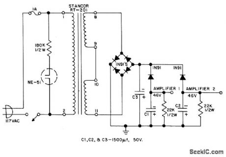
Diode decoupling provides 80 db of separation between two stereo amplifier channels. Designed for use with 10-W power amplifiers.- Transistor Manual, Seventh Edition, General Electric Co., 1964, p 261. (View)
View full Circuit Diagram | Comments | Reading(899)
STEREO_MULTIPLEX_OSCILLATOR
Published:2009/7/24 3:16:00 Author:Jessie
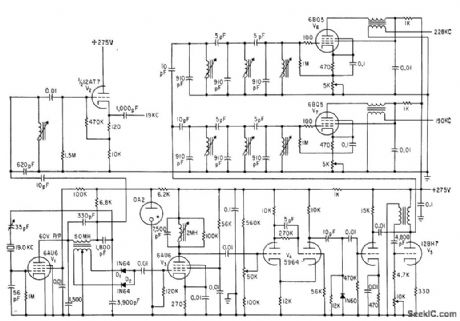
Output of 19-kc crystal oscillator is amplified by V2 for pilot subcarrier. Same frequency is doubled by D1-D2, amplified by V3, and shaped by monostable mvbr V4 to provide trigger pulses. for blocking oscillator VS, from which fifth and sixth harmonics (190 and 228 kc) are taken and amplified by V6 and V7 for use as carrier signals.-Modifying an F-M Transmitter for Compatible Stereo Multiplex, Electronics, 34:28, p 60-62. (View)
View full Circuit Diagram | Comments | Reading(929)
STEREO_MULTIPLEX_SUBCARRIER_GENERATOR
Published:2009/7/24 3:25:00 Author:Jessie
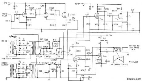
Double-sideband suppressed-carrier a-m subcarrier generator uses inverse feedback for low distortion. Double-modulcation system is used.-Modifying an F-M Transmitter for Compatible Stereo Multiplex, Electronics, 34:28, p 60-62. (View)
View full Circuit Diagram | Comments | Reading(1031)
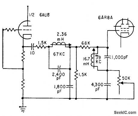
F_M_STEREO_DEMODULATOR
Published:2009/7/24 3:24:00 Author:Jessie
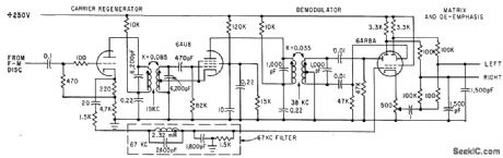
Signal from f-m discriminator is passed through 67-kc rejection fiber to control grid of 6AR8A as electronic switch, while high-amplitude 38-kc sine wave is applied to its deflection plates.One plate produces mainly left signed, and other produces mainly right signal. Cathode gives balanced L+R signal.-L. Solomon, Multiplex Adaptors for Compatible F-M Stereo Retention, Electronics, 34:33, p 45-.47. (View)
View full Circuit Diagram | Comments | Reading(860)
STEREO_HEADPHONE_AMPLIFIER
Published:2009/7/24 3:21:00 Author:Jessie

Will drive dyanamic headphones of 75 to 400 ohms impedance to power level of 60 mw. Program source may be tuner or ceramic car tridge. Frequency response is fiat within 0.33 db from 20 cps to 20 kc. High input impedance, 1 meg up to 2.5 kc and decreasing to 400K at 15 kc, is obtained by using bootstrapped bias network for Q1 along with negative feedback.- Transistor Manual, Seventh Edition, General Electric Co., 1964, p 272. (View)
View full Circuit Diagram | Comments | Reading(858)
| Pages:27/54 At 202122232425262728293031323334353637383940Under 20 |
Circuit Categories
power supply circuit
Amplifier Circuit
Basic Circuit
LED and Light Circuit
Sensor Circuit
Signal Processing
Electrical Equipment Circuit
Control Circuit
Remote Control Circuit
A/D-D/A Converter Circuit
Audio Circuit
Measuring and Test Circuit
Communication Circuit
Computer-Related Circuit
555 Circuit
Automotive Circuit
Repairing Circuit