
Index 206
STEREO_REVERBERATION
Published:2009/7/10 6:12:00 Author:May

Uses National LM377 dual power amplifier as driver for springs acting as mechanical delay lines. Used to enhance performance of stereo music system by adding artificial reverberation to simulate reflection and re-reflection of sound off walls, ceiling, and floor of listening environment. Amplifier has frequency response of 100-5000 Hz, with roll off below 100 Hz to suppress booming. Recovery amplifier uses LM387 low-noise dual preamp, and another LM387 provides mixing of delayed signal with original in inverting summing configuration. Output is about half of original signal added to all of delayed signal.- Audio Handbook, National Semiconductor, Santa Clara, CA, 1977, p 5-7-5-10. (View)
View full Circuit Diagram | Comments | Reading(872)
SUM_AND_DIFFERENCE
Published:2009/7/10 6:11:00 Author:May
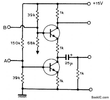
Simple circuit using two BC109 or equivalent transistors is effective for summing and differencing two signals, as required in stereo and quadraphonic sound applications. For resistor values shown, upper output is -1/2(A + B) and lower output is -1/2(A - B). Will handle input signals up to 1.4 V. Bottom of 68K resistor should go to ground.-B. J. Shelley, Active Sum and Difference Circuit, Wireless World, July 1974, p 239. (View)
View full Circuit Diagram | Comments | Reading(1486)
STEREO_FM_DEMODULATOR
Published:2009/7/10 6:07:00 Author:May
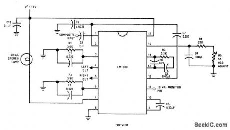
Single National LM1800 IC converts composite AF input signal to left and right signals for audio power amplifiers LED with series resistor can be used in place of 100-mA lamp.-“Audio Handbook,” National Semiconductor, Santa Clara, CA, 1977, p 3-23-3-27. (View)
View full Circuit Diagram | Comments | Reading(839)
REAR_CHANNEL_AMBIENCE
Published:2009/7/10 6:05:00 Author:May
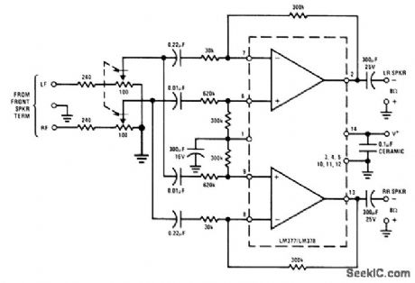
Can be added to existing left front and right front loudspeakers of stereo system to extract difference signal for combining with some direct signal (R or L) to add fullness for concert-hall realism during re-production of recorded music. Very little power is required for pair of rear loudspeakers, and this can be furnished by National LM377/LM378 dual-amplifier IC operating from about 24-V supply.- Audio Handbook, National Semi-conductor, Santa Clara, CA, 1977, p 4-8-4-20. (View)
View full Circuit Diagram | Comments | Reading(761)
FM_NOISE_SUPPRESSOR
Published:2009/7/10 6:04:00 Author:May
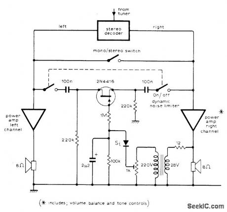
Circuit acts as noise limiter to help produce pseudostereo sound having reduced noise, to offset noise signal heard during weak passages during stereo reception of FM stations. FET short-circuits both audio channels when audio signal strength drops sufficiently to make noise objectionable. H this voltage is insufficient to drive FET, amplifier or transformer must be used.-J. W. Richter, Stereo Dynamic Noise Limiter, Wire-less World, Oct, 1975, p 474. (View)
View full Circuit Diagram | Comments | Reading(965)
256_NEGATIVE_STEPS
Published:2009/7/10 6:01:00 Author:May
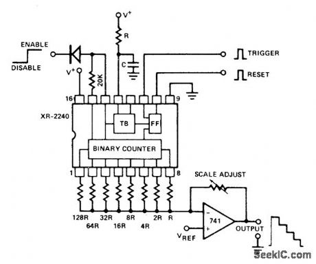
Interconnection of Exar XR-2240 programmable timer/counter with 741 opamp and precision resistor ladder forms staircase generator. Reset pulse drives output low. When trigger is applied, output goes high and circuit generates negative-going staircase having 256 equal steps. Duration of each step is equal to time-base period as determined by values used for R and C. Staircase is stopped by applying disable signal (less than 1.4V) to pin 14 through steering diode. Supply voltage range is 4-15 V. If counter cannot be triggered when using supply above 7 V and less than 0.1μF for C, connect 300 pF from pin 14 to ground.- Timer Data Book, Exar Integrated Systems, Sunnyvale, GA, 1978, p 11-18. (View)
View full Circuit Diagram | Comments | Reading(2389)
PULSE_TRAINS_FORM_STAIRCASE
Published:2009/7/10 5:59:00 Author:May
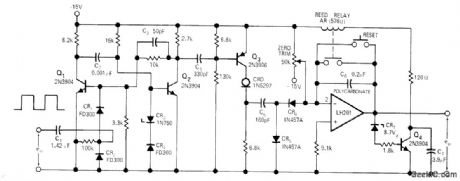
Circuit accepts pulse trains from pulse-generating position transducer and produces staircase wave-form as analog input for horizontal axis of XY recorder or storage scope. Current-regulating diode serves as constant-current source for staircase generator that produces analog out-put proportional to number of input pulses. Mono switches on Q3 for constant time duration with every pulse, to ensure that C5 gets same amount of charge regardless of pulse rate. Relay resets integrator to zero when output voltage reaches almost 8.7 V, to prevent data from being lost if opamp saturates before data run is completed.-R. G. Warsinski, Staircase Generator Uses Current-Regulating Diode, EDN|EEE Magazine, Aug. 1, 1971, p 46. (View)
View full Circuit Diagram | Comments | Reading(1301)
SQUARE_TO_STEP
Published:2009/7/10 5:56:00 Author:May
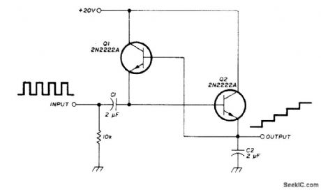
Simple staircase generator circuit converts square wave into staircase voltage output. Each step approximates level of input pulse. First pulse charges C2 to amplitude of input pulse. After pulse, voltage across C2 acts through on to charge Q1 to same voltage. Next pulse adds to voltage across C2, doubling its charge. Each subsequent pulse steps up height of staircase until it reaches level of supply voltage.-J. Fisk, Circuits and Techniques, Ham Radio, June 1976, p 48-52. (View)
View full Circuit Diagram | Comments | Reading(5442)
NEGATIVE_TRIGGERING
Published:2009/7/10 5:54:00 Author:May
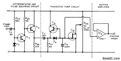
Standard transistor pump circuit is driven by differentiating and squaring circuit designed so each staircase block is triggered by negative edge rather than by pulse. Circuit was developed for FET curve tracer, and can be used in other applications where only resetting edge of normal sawtooth is available as trigger. R28 changes number of steps produced before staircase is reset. Tr6 is Texas Instruments 43, IC opamp is SN72741P, transistors are BC182L or equivalent, and diodes are 1S44.-L. G. Cuthbert, An F.E.T. Curve Tracer, Wireless World, April 1974, p 101-103. (View)
View full Circuit Diagram | Comments | Reading(1074)
SEVEN_STEPS
Published:2009/7/10 5:53:00 Author:May
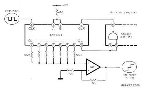
Circuit shown generates seven identical steps before waveform is repeated. Number of steps can be increased by cascading two or more SN74164 shift registers, or reduced by taking dear pulse from earlier a output of register.-P. Cochrane, Simple Staircase Generator, Wireless World, April 1976, p 63. (View)
View full Circuit Diagram | Comments | Reading(1326)
COUNTER_TYPE_CO_NVERTER
Published:2009/7/10 5:52:00 Author:May
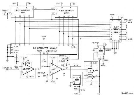
Clock-driven counter drives Harris HI-1080 D/A converter producing staircase voltage ramp. When converter output voltage equals analog input voltage as determined by HA-2602 comparator, comparator changes state. At that instant, state of counter represents 8-bit digital equivalent of analog input. Data output from latch is complement of digital value. Input range is 0-10 V. Other input ranges, positive or negative, are obtained by changing opamp gain or polarity or by adjusting 1K reference pot. Accuracy is maintained within 1/2 LSB at clock rates up to 330 kHz.- Linear & Data Acquisition Products, Harris Semiconductor, Melbourne, FL, Vo1, 1, 1977, p 7-33-7-35 (Application Note 512). (View)
View full Circuit Diagram | Comments | Reading(1015)
4_400_Hz_BIPOLAR
Published:2009/7/10 5:51:00 Author:May
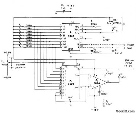
Single 2240 serves as time-base generator with Rt determining frequency in range of 4-400 Hz. Digital output is converted to analog form by 7530 10-bit CMOS multiplying D/A converter. Reference voltage can be varied up to ±10 V to give variable-amplitude bipolar staircase output in same amplitude range, with 255 staircase steps corresponding to 8-bit count of 2240. Opamp A3 serves as current-to-voltage convener for changing ±1 mA output current of 7530 to ±10 V swing for staircase.-W. G. Jung, IC Timer, Cookbook, Howard W. Sams, Indianapolis, IN, 1977, p 224-226. (View)
View full Circuit Diagram | Comments | Reading(672)
48_Hz_12_STEP
Published:2009/7/10 5:50:00 Author:May
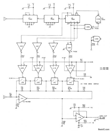
Used to provide 12 shades of gray for reception of satellite facsimile weather pictures. Input 1 is 2400-Hz square wave obtained from separate reference oscillator. Input 2 is 2400-Hz sine wave having 1 V P-P maximum voltage. U9 is 4-bit binary counter having special reset provided by U10A and U10B at count 12 to give desired 12 states. Outputs of U9 are used to adjust gain of U16A in 12 steps. Article describes operation in detail and gives circuits for reference oscillator and power supply.-R. Cawthon, Toward a More Perfect Weather Picture, 73 Magazine, April 1978, p 116-118. (View)
View full Circuit Diagram | Comments | Reading(668)
STEPS_FOR_CURVE_TRACER
Published:2009/7/10 5:49:00 Author:May
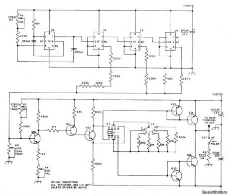
Square waves with 1-V amplitude and 1/60-s period, 2 V at 1/30-s, and 4 V at 11-15 s are generated by μL914 MVBR and μL923 flip-flops U2-U4, for combining in simple ladder network to give staircase waveform. Flip-flops count down MVBR output. Complementary-amplifier stage Q10-Q11 drives phase splitter Q12. Output of phase splitter goes through S1 to appropriate current source, Q13-Q14 or Q15-Q16, for supplying base terminal of device under test (DUT). Use 2N3904 for Q10, Q12, Q15, and Q16. Use 2N3906 for Q11, Q13, and Q14,-R. P. Ulrich, A Semiconductor Curve Tracer for the Amateur, QST, Aug. 1971, p 24-28. (View)
View full Circuit Diagram | Comments | Reading(1637)
SIX_STEP_COMPOSITE_VIDEO
Published:2009/7/10 5:46:00 Author:May
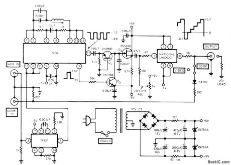
Circuit accepts negatively referenced output signals of TV sync generator and delivers 1 V P-P six-step composite video signal to 75-ohm load. 74121 mono changes wide horizontal blanking pulse to correct width for triggering oscillator IC. National LH002C current driver provides low-impedance drive capability for video signal. Used in testing TV sets and VTR decks.-M. J. Salvati, VFO Adds Versatility to TV Sync Generator, EDN Magazine, May 20, 1974, p 70 and 72. (View)
View full Circuit Diagram | Comments | Reading(3633)
500_MC_SMALL_SIGNAL
Published:2009/7/10 5:45:00 Author:May
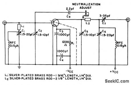
Uses 2N3570 silicon transistor to give 16 db gain.-Texas Instruments Inc., Solid-State Communications, McGraw-Hill,N.Y.,1966,p 259. (View)
View full Circuit Diagram | Comments | Reading(650)
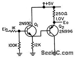
BASIC_DARIJNGTON
Published:2009/7/10 5:44:00 Author:May
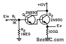
When used as betasquaring circuit, chief drawback is severe change in off'set voltage with temperctture.If base-emitter voltage varies about 2 mv per degree Q, 25℃ temperature change can give output change of 50 mv per stage.-R. C. Going, Temperature.Stabilize d Darlington, EEE, 11:7, p 28-29.
(View)
View full Circuit Diagram | Comments | Reading(614)
COMPLEMENTARY_TRANSISTOR_DARLINGTON_
Published:2009/7/10 5:43:00 Author:May
Use of complementary transistors virtually eliminates undesired offset voltages through cancelling action. Germanium transistors may be used in place of silicon units shown.-R. C, Going, Temperature-Stabilized Darlington, EEE, 11:7, p 28-29. (View)
View full Circuit Diagram | Comments | Reading(922)
Q_MULTIPLIER
Published:2009/7/10 5:43:00 Author:May
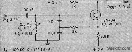
Circuit Q in single-coil arrangement is insensitive to drift in trctnsistor parameters, permitting use in filter and oscillator design.-J. R. Woodbury, Simple Transistor Q-Muhiplier or Oscillator, Electronics, 35:22, p 53-54. (View)
View full Circuit Diagram | Comments | Reading(2554)
COMPLEMENTARY_CURRENT_MULTIPLIER
Published:2009/7/10 5:41:00 Author:May
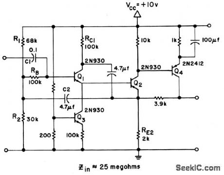
Use of complementary transistor Q4 increases current multiplicotion and increases gain at emitter of Q2 by rctising effective value of RE2. This higher gain makes bootstrapping more effective. Input impedance is 25 meg.Response is 50 cps to 1 Mc.-Texas Instruments Inc., Solid-State Communicotions, McGraw-Hill, N.Y., 1966, p 183. (View)
View full Circuit Diagram | Comments | Reading(958)
| Pages:206/471 At 20201202203204205206207208209210211212213214215216217218219220Under 20 |
Circuit Categories
power supply circuit
Amplifier Circuit
Basic Circuit
LED and Light Circuit
Sensor Circuit
Signal Processing
Electrical Equipment Circuit
Control Circuit
Remote Control Circuit
A/D-D/A Converter Circuit
Audio Circuit
Measuring and Test Circuit
Communication Circuit
Computer-Related Circuit
555 Circuit
Automotive Circuit
Repairing Circuit