
Basic Circuit
Index 185
NOISE_SUPPRESSION
Published:2009/7/16 10:16:00 Author:Jessie
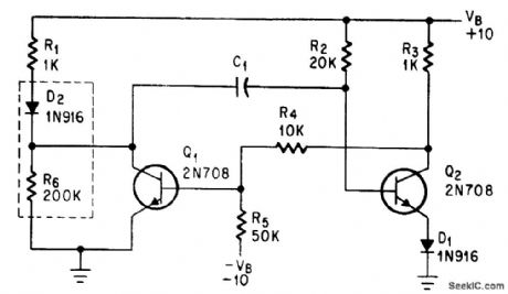
Diode in collector circuit makes monstable mvbr immune to most noise pulses.-B. D. Simmonds, Diode Quiets Input to Monostable Multi, Electronics, 38:19, p 99-100. (View)
View full Circuit Diagram | Comments | Reading(923)
5_V_TO_4_V_CONVERTER
Published:2009/7/13 2:57:00 Author:May
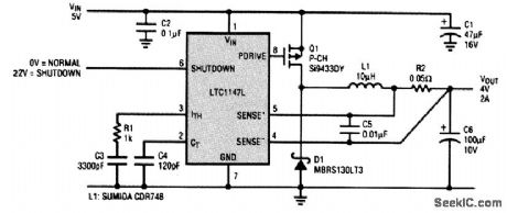
Generating a 4-V supply voltage for some of the new microprocessors from a 5-V main requires a low-voltage-loss capability in an efficient switching power supply. The LTC1147L circuit shown provides this capability in only 0.6 in2 of board space. The LTC1147L is a high-efficiency step-down switching regulator controller that provides gate drive control for an external P-channel MOSFET switch. Up to 100 percent duty cycle is possible with the LTC1147L, allowing the output voltage to be close to the input voltage. This device uses a constant off-time architecture and can operate at switching frequencies eiceeding 400 kHz. The LTC1147L is an adjustable device, with the output voltage set by an external resiator divider network. Maximum load current is set by the value of the current sense resistor R2. (View)
View full Circuit Diagram | Comments | Reading(841)
TRIAC_LAMP_DIMMER
Published:2009/7/13 2:57:00 Author:May
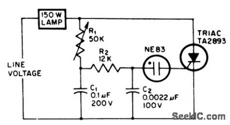
Can easily be buih into lamp socket or fixture. Uses minimum number of components.-J. Eimbinder, SCRs In the Consumer Market, EEE, 14:8, p100-103. (View)
View full Circuit Diagram | Comments | Reading(1486)
SCR_LAMP_DIMMER
Published:2009/7/13 2:55:00 Author:May
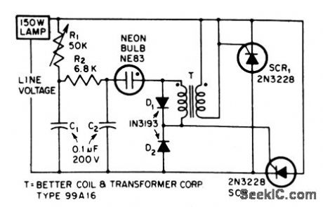
Can easily be built into lamp socket or fixtore.-J. Eimbinder, SCRs in The Consumer Market, EEE, 14:8, p100-103. (View)
View full Circuit Diagram | Comments | Reading(976)
SIMPLE_5_V_TO_33_V_CONVERTER
Published:2009/7/13 2:53:00 Author:May
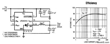
In portable logic systems requiring mixed 5-V and 3.3-V supplies, space and efficiency are paramount. Enter the LTC1574-3.3, a small and simple solution that provides over 90 percent efficiency.The LTC1574-3.3 features an intemal Schottky diode, reducing the external component count to just three parts. This high-efficiency circuit uses all surface-mount components, and employs Burst Mode operation to extend high efficiency to low current levels (see graph). A low-loss internal power MOSFET (RDS = 1.2 Ω is typical for this circuit) switch and constant off-time architecture are key in achieving this high efficiency. The LTC1574 can be shut down, limiting the supply current to 25 μA (max). (View)
View full Circuit Diagram | Comments | Reading(728)
FULL_WAVE_SYNCHRONOUS_BECTIFIER
Published:2009/7/13 2:52:00 Author:May
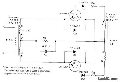
Transistors are biased on alternately by AC input voltage, to supply load current on alternate half-cycles. Silicon diodes D1 and D2 protect transistors from charging current of capacitive load when circuit is turned on, Capacitor discharge problems are minimized by use of diodes D3 and D4 in base circuits of transistors.-B. C. Shiner, Improving the Effilciency of Low Voltage, High-Current Rectification, Motorola, Phoenix, AZ, 1973, AN-517, p 4. (View)
View full Circuit Diagram | Comments | Reading(936)
BASIC_HARTLEY
Published:2009/7/16 5:28:00 Author:Jessie
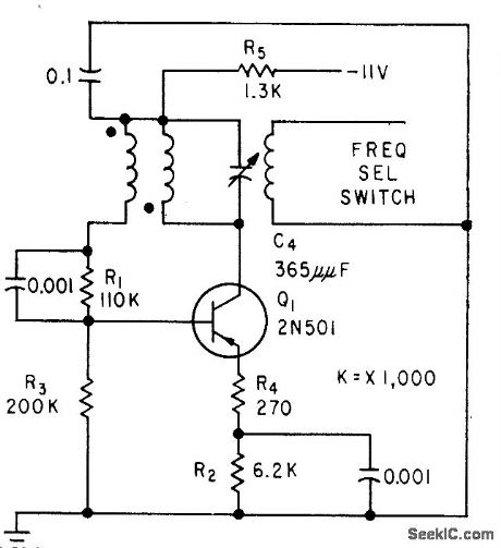
Sine-wave oscillator, tunable over 3:1 frequency range by C4, uses switching transistor. Used in pulse generator for testing high-speed digital computers.-L. Neumann, Transistorized Generator for Pulse Circuit Design, Electronics, 32:14, p 47-49. (View)
View full Circuit Diagram | Comments | Reading(807)
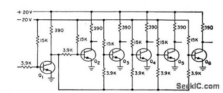
3_LIGHT_MARKER_BEACON_ADAPTER
Published:2009/7/16 5:27:00 Author:Jessie
Separates the three marker beacon modulating frequencies and converts them to voltages for operating three color-coded lights in air-craft. When added to one-light receiver, adapter requires only two more electronic switches, in addition to loss amplifier and filters.-R. G. Erdmann, Transistor Dual Conversion for Marker-Beacon Receivers, Electronics, 32:19, p 59-61. (View)
View full Circuit Diagram | Comments | Reading(1131)
ADJUSTABLE_ODDS_LORRERY
Published:2009/7/13 2:48:00 Author:May
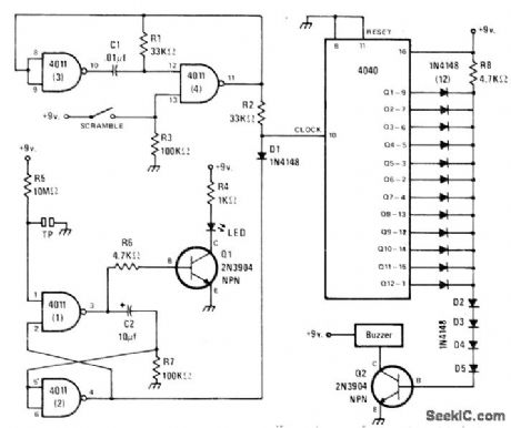
Odds for lottery are set by diode matrix connected to output of 4040 counter. Range is from 1 :2 to 1 : 1024. To use, close scramble switch for a second or two to make free-running oscillator drive counter at high rate, then let contestant hit toueh plate to trigger flip-flop that advances counter one step. If counter was frozen at next to last connected diode, next diode is biased off and Q2 energizes buzzer. For 50-50 odds, connect only diode at output Q1. For odds of 1 in 10, connect diodes only to outputs Q2and Q4 for binary 1010 or 10. With all diodes connected as shown, odds are 1:1024.-J. Sandier, Play 'Random Chance,' Modern Electronics, Oct. 1978, p 42-43 and 88. (View)
View full Circuit Diagram | Comments | Reading(2410)
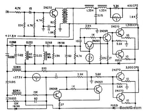
1_LIGHT_AIRBORNE_MARKER_BEACON
Published:2009/7/16 5:20:00 Author:Jessie
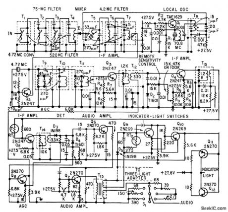
Dual-conversion 75-Mc receiver has high first i-f for good image rejection and lower second i-f for stable gain. Responds to any of three modulating frequencies (3,000 cps airways, 400-cps outer runway, and 1,300-cps middle runway).-R, G. Erdmann, Transistor Dual Conversion for Marker-Beacon Receivers, Electronics, 32:19, p 59-61. (View)
View full Circuit Diagram | Comments | Reading(1262)
MONOSTABLE_OR_CIRCUIT
Published:2009/7/16 5:16:00 Author:Jessie
Uses resistance-coupled inputs to drive tunnel diode.-F.Leary, Computers Today, Electronics, 34;17, p 64-94. (View)
View full Circuit Diagram | Comments | Reading(642)
NEON_PHOTOCONDUCTOR_INVERTER
Published:2009/7/16 5:15:00 Author:Jessie
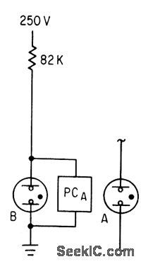
Cadmium selenide photoconductor PC and Ne2H neon lamps give low-speed inverter action for logic circuits at low cost. Neon B is on when there is no input. When neon A provides input, PC turns neon B off.-J. L. Patterson, Will Neon Photoconductors Replace Relays in Low-Speed Logic?, Electronics, 36:18, p 46-49. (View)
View full Circuit Diagram | Comments | Reading(801)
SINGLE_SUPPLY_NOP_GATE
Published:2009/7/16 5:15:00 Author:Jessie
Low storage time allows medium-speed operation without turn-off base bias supply. Maximum is 1 Mc for two cascaded logic stages.-D. Hull, Using Epitaxial Transistors in Switching and R-F Circuits, Electronics, 34:13, p 52-53. (View)
View full Circuit Diagram | Comments | Reading(682)
SERIES_PNP_BASIC_LOGIC
Published:2009/7/16 5:14:00 Author:Jessie
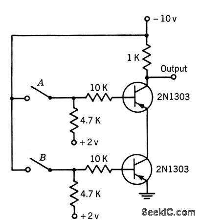
Serves as and gale for normally open switches, and as or gate for normally closed switches. Provides phase inversion of input.-Texas Instruments Inc., Transistor Circuit Design, McGraw-Hill, NY, 1963, p 388. (View)
View full Circuit Diagram | Comments | Reading(763)
TWO_INPUT_NIPO_NOR_GATE
Published:2009/7/16 5:13:00 Author:Jessie
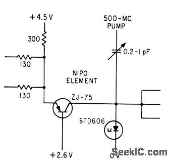
Pumped tunnel diode-transistor logic gives 2-gc rate for uhf shift register using negative input-positive output gate having gain of 3 and 50.mw power drain.-Tunnel Diode-Transistor Provides Fast Logic, Electronics, 35:11, p 72. (View)
View full Circuit Diagram | Comments | Reading(723)
TWO_CELL_TO_5_V_BOOST_CONVERTER
Published:2009/7/13 2:43:00 Author:May
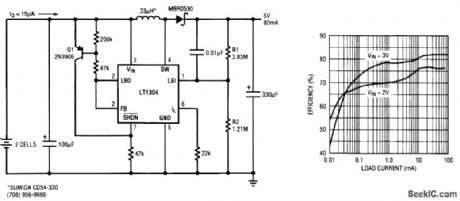
Extending the battery life of a portable device that spends most of its life time in standby mode is critical in two-cell applications. The standard LT1304 boost circuit requires two capacitors, one diode, and one inductor and provides 5 V at 200 mA from a two-cell battery with 80 percent typical efficiency. For improved efficiency at very light loads, the LT1304 switching regulator circuit shown achieves an efficiency of 50 percent at just 10 μA of load current. As indicated in the graph, high efficiency over a very wide range of load current is obtained by using the extra circuitry to control Burst Mode operation. The LT1304 is a micropower step-up dc-to-dc converter with an internal comparator that is operational in shutdown. The peak switch current limit can be set up to 1 A by the resistor at the ILIM input. In this circuit, it is set to 500 mA. The input voltage range extends down to 1.65 V, ensuring operation-even as the two-cell battery voltage drops during discharge. The on-board comparator shuts down the LT1304 micropower regulator when the output voltage is higher than the target 5-V output. In shutdown, the LT1304 consumes 10 μA of current, which is less than one-tenth of its active quiescent current of 120 μA. When the output voltage begins to droop below the target 5-V output, the comparator switches the LT1304 on again to recharge the output capacitor. (View)
View full Circuit Diagram | Comments | Reading(909)
THIN_FILM_TOGGtING_WITH_TRANSISTOR
Published:2009/7/16 5:12:00 Author:Jessie

Use of transistor stage permits cascading as for counters. Tunnel diode, which controls conducting state of transistor, is biased to have output voltages of 0.05 and 04 V. Additional film winding is needed because of phase reversal by transistor.-I. A Smay and A V. Pohm, Design of logic Circuits Using Thin Films and Tunnel Diodes, Electronics, 34;35, p 59-61. (View)
View full Circuit Diagram | Comments | Reading(759)
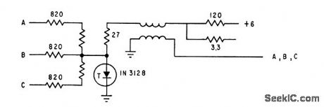
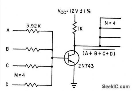
MAJORITY_GATE
Published:2009/7/16 5:09:00 Author:Jessie
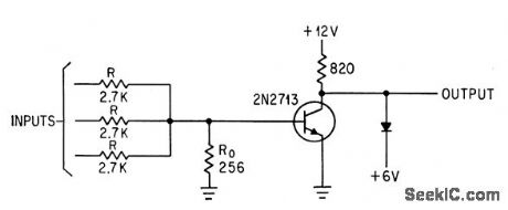
With odd number of inputs and resistor-summer, threshold logic transistor is virtually off up to 0.5 V base-emitter voltage and on at 0.7V. Output is inverted.-W. A. Sauer, How to Achieve Majority and Threshold Logic with Semiconductors, Electronics, 36:48, p 23-25. (View)
View full Circuit Diagram | Comments | Reading(1078)
NOR_CIRCUIT
Published:2009/7/16 5:04:00 Author:Jessie
With 2N834 epitaxial mesa transistors, turn-on time. is 80 nsec, and turn off 90 nsec, as compared to 111-nsec turn-on and 140.nsec turn-off for nonepitaxial 2N706 mesa transistors in same circuit.-W. D.Roehr, Epitaxial Process Improves Transistor Characteristics, Electronics, 34:9, p 52-53. (View)
View full Circuit Diagram | Comments | Reading(963)
TUNNEL_DIODE_OR_GATE
Published:2009/7/16 5:04:00 Author:Jessie
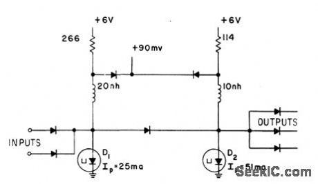
Two monoslable multivibrators are cascaded to provide cur rent gain at 200 Mc. Output is obtained when either of input currents rises above 8 ma.-E. Gottlieb and J. Giorgis, Tunnel-Diode Switching Circuits, Electronics, 36:27, p 26-31. (View)
View full Circuit Diagram | Comments | Reading(0)
| Pages:185/471 At 20181182183184185186187188189190191192193194195196197198199200Under 20 |
Circuit Categories
power supply circuit
Amplifier Circuit
Basic Circuit
LED and Light Circuit
Sensor Circuit
Signal Processing
Electrical Equipment Circuit
Control Circuit
Remote Control Circuit
A/D-D/A Converter Circuit
Audio Circuit
Measuring and Test Circuit
Communication Circuit
Computer-Related Circuit
555 Circuit
Automotive Circuit
Repairing Circuit