
Communication Circuit
Index 30
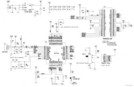
children anti-lost reminder transceiver module composed of the RCMlA/RCMlB
Published:2011/5/9 4:19:00 Author:TaoXi | Keyword: children, anti-lost reminder, transceiver module
This circuit is composed of the transmitter and receiver, the core components are the RCM1A and RCM1B. (View)
View full Circuit Diagram | Comments | Reading(688)
U4055B-communication integrated circuit diagram
Published:2011/5/9 1:02:00 Author:Nicole | Keyword: communication
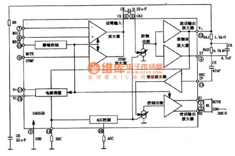
U4055B is a communication integrated circuit, as communication singal process circuit, it is widely used in communication equipments.
1. internal circuit block diagram
The internal circuit block diagram of U4055B integrated block is shown in the figure 1-1.
The figure 1-1 is the internal circuit block diagram of U4055B integrated block
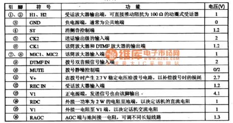
2. 5-foot function and data
The pin function and data of U4055B integrated circuit is shown in the table 1-2.
The table 1-2 is the pin function and data of U4055B integrated circuit (View)
View full Circuit Diagram | Comments | Reading(943)
FM / FSK 27MHz transmitter circuit
Published:2011/5/8 3:50:00 Author:John | Keyword: FM / FSK 27MHz transmitter circuit
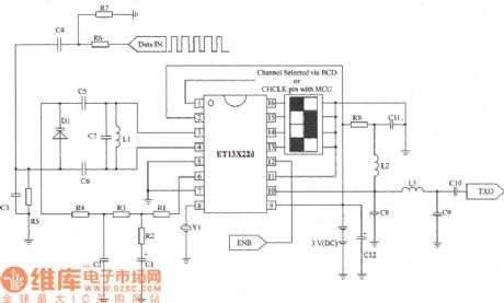
ETl3X220 is a low-cost single-chip transmitter chip which is connected through RF. It can provide 10 communications. And it is suitable for applications of wireless mouse, keyboard and other communication products. The main technical features are as follows: Analog FM or digital FSK modulation mode 5 Channel spacing frequency is about 30 kHz; Supply voltage is 2.3 ~ 3.6 V;Current consumption is 8 mA and low-power mode is 5 μA. (View)
View full Circuit Diagram | Comments | Reading(5049)
ASK 315 MHz transmitter circuit
Published:2011/5/8 3:13:00 Author:John | Keyword: transmitter circuit
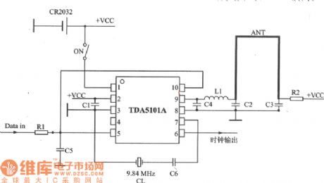
TDA510lA is a transmitter chip of high efficiency power amplifier. It can be used in keyless entry systems, remote control systems, communications and security systems. The main technical features are as follows: Work frequency band is 315 MHz; ASK modulation;Power supply voltage is 2.1 ~ 4 V;Low voltage detection output is available;Maximum operating current is 9 mA (emission enabled), and standby mode current is l00 nA;It has high efficient power amplifier. And the amplifier can drive the loop antenna with low current consumption and extend service life of the battery. (View)
View full Circuit Diagram | Comments | Reading(4814)
SMB820OCP FSK decoder integrated circuit diagram
Published:2011/5/5 22:04:00 Author:Rebekka | Keyword: FSK decoder, integrated circuit
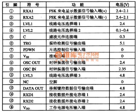
SMB820OCP is a frequency shift keying decoder integrated circuit. It is widely used for receiving and displaying the calling number of switch equipment and information products (such as Caller ID cordless / corded telephone, etc.). 1. Pin functions and data.SMB820OCP integrated circuit uses double row 16-pin IC DIP packages, the pin functions and data are listed in table 1.
Table 1 SMB822OCP IC pin functions and data 2. Similar IC The pinouts and functions of SMB820OCP and HR220, MCl45447P are basically the same and the three can be directly used interchangeably. (View)
View full Circuit Diagram | Comments | Reading(809)
Full-bridge type inverter circuit
Published:2011/5/5 2:55:00 Author:muriel | Keyword: Full-bridge type , inverter circuit

Single-phase inverter circuitincludes push-pull type, half bridge type and full bridge type, in which the full bridge inverter circuit is themost common. The principle ofSingle-phase full-bridge inverter circuitis shown in Figure (a). (B) pictureisthe excitation signal and the output voltage waveform.
(View)
View full Circuit Diagram | Comments | Reading(3883)
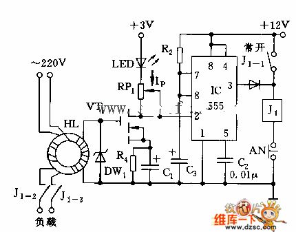
Simple Leakage Protection Circuit
Published:2011/5/3 5:20:00 Author:Felicity | Keyword: Simple Leakage Protection Circuit,
View full Circuit Diagram | Comments | Reading(847)
Negative sequence voltage-phase protection circuit diagram 2
Published:2011/5/3 3:10:00 Author:Rebekka | Keyword: Negative sequence, voltage-phase protection
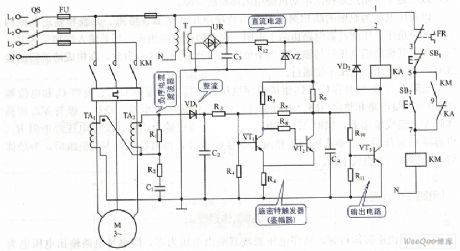
Negative sequence voltage-phase protection circuit diagram (View)
View full Circuit Diagram | Comments | Reading(1396)
Optical signal receiving circuit
Published:2011/4/29 23:31:00 Author:Nicole | Keyword: optical signal receiving
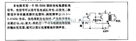
This circuit adopts a IR-B2M type photoelectric cell to receive optical signal. The optical signal can be visible light or infrared light, when it uses LED or semiconductor laser as light source, the best modulation frequency is 0.5~2.0kHz. When the light shines on photoelectric cell, the produced AC voltage is amplified by Q1, Q2, you can clearly hear the sound with a earphone, after a transformer which is fitting with the earphone resistance. (View)
View full Circuit Diagram | Comments | Reading(717)
Light beam receiving circuit
Published:2011/4/29 4:43:00 Author:Nicole | Keyword: light beam receiving
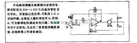
This circuit demodulates amplitude modulation light beam into audio singal to drive the transistor radio earphone with 500~1000Ω resistance. Detection transformer is adopted, and it is served with a 8Ω miniature loudspeaker. The gain of operational amplifier is controlled by R3, R3 is a trimming resistor or potentiometer. This circuit can be used in transmitter, providing LED with amplitude modulation, it also can be used as language communication for a short distance. (View)
View full Circuit Diagram | Comments | Reading(692)
thermometer radiation circuit
Published:2011/5/1 23:39:00 Author:Christina | Keyword: thermometer, radiation
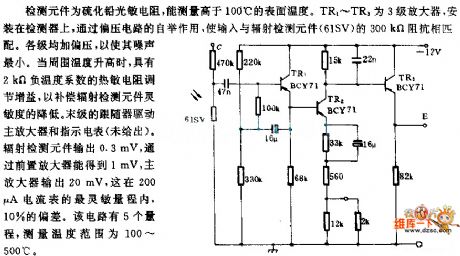
Detection device is the PbS photoresistor, it can detects the surface temperature higher than 100 ℃. TR1 ~ TR9 are the three-step amplifier that is installed on the detector. The bootstrap effect of the off-bias circuit makes the input voltage match with the radiation monitor device (61SV)'s 300kΩ impedance. Levels were added the bias to minimize the noise. When the ambient temperature rises, thermistor with the 2kΩ negative temperature coefficient adjusts the gain, to compensate the lower of the radiation detect device's sensitivity. The last stage of follower drives the main amplifier and instruction meter. Radiation detect device outputs 0.3mV, and this voltage gets through the pre-amplifier then becomes 1mV, the main amplifier outputs 20mV, it is in the range of 200uA ammeter's most sensitive range (deviation in 10%). This circuit has five ranges, the temperature range is 100 ~ 500 ℃.
(View)
View full Circuit Diagram | Comments | Reading(774)
Preventing outside lines telephone circuit diagram
Published:2011/4/29 3:20:00 Author:Rebekka | Keyword: Preventing outside lines telephone
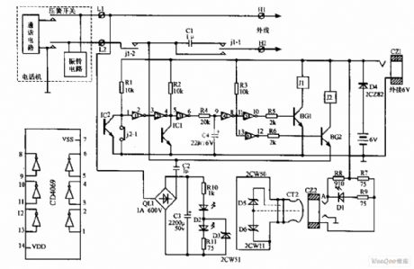
Preventing outside lines telephone circuit diagram. (View)
View full Circuit Diagram | Comments | Reading(814)
50kHz FM optical receiver circuit
Published:2011/4/15 5:26:00 Author:May | Keyword: FM, optical receiver
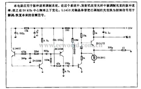
This circuit is used in impulse speed modulation system. In this system, transmitter change impulse speed of modulated beam in optical fiber, let it change around 50kHz center frequency. L14G2 optical transistor convert molulated light to radio-frequency signal. The radio-frequency isusedfor demodulating. It can recover original audio frequency signal.
(View)
View full Circuit Diagram | Comments | Reading(2130)
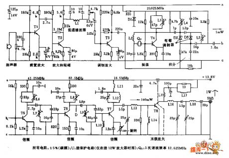
The transmitter circuit of discordant harmonic with 200MHZ frequency
Published:2011/4/23 9:24:00 Author:May | Keyword: transmitter, discordant harmonic, 200MHZ frequency
Frequency 200MHz not harmonic transmitter circuit is shown in the following diagram:
(View)
View full Circuit Diagram | Comments | Reading(742)
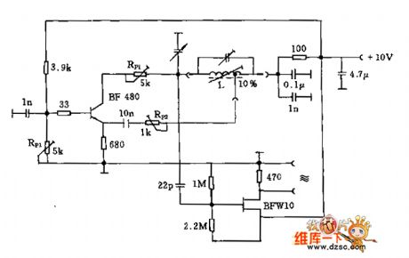
IW transmitter circuit with frequency range of 16MHz
Published:2011/4/11 2:38:00 Author:may | Keyword: IW transmitter, 16MHz, frequency range
IW transmitter circuit of frequency 16MHz range is shown in the following diagram: (View)
View full Circuit Diagram | Comments | Reading(889)
88MHz-108MHz 15W FM transmitter high-frequency amplifier circuit diagram
Published:2011/4/27 3:05:00 Author:Rebekka | Keyword: FM transmitter, high-frequency amplifier
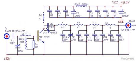
88MHz-108MHz 15W FM transmitter high-frequency amplifier circuit diagram is shown as above. (View)
View full Circuit Diagram | Comments | Reading(4869)
80mW FM transmitter circuit diagram
Published:2011/4/27 3:02:00 Author:Rebekka | Keyword: FM transmitter
80mW FM transmitter circuit diagram is shown as above. (View)
View full Circuit Diagram | Comments | Reading(2355)
Single-tube radio transmitter circuit diagram
Published:2011/4/27 3:00:00 Author:Rebekka | Keyword: Single-tube radio, transmitter circuit
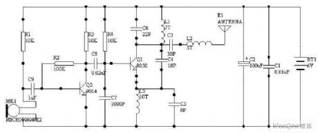
Single-tube radio transmitter circuit diagram is shown as above.
Note: The launch transistor uses the 9018.
(View)
View full Circuit Diagram | Comments | Reading(2791)
PFS-4091 High sensitive infrared receiving device the internal circuit diagram
Published:2011/4/24 4:06:00 Author:Rebekka | Keyword: infrared receiving device
(View)
View full Circuit Diagram | Comments | Reading(1010)
Composed of MC145026 and 145027 infrared transmitter and receiver circuit diagram
Published:2011/4/22 3:15:00 Author:Rebekka | Keyword: infrared transmitter and receiver
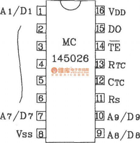
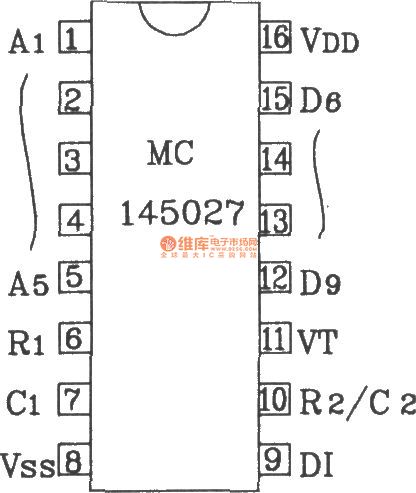
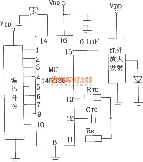
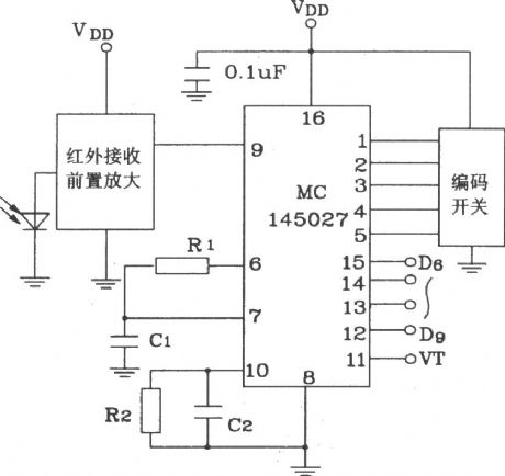
MC145026/145027 are dedicated remote control encoder / decoder ICs. They can achieve binary or ternary addressing(ternary makes encoding / decoding become the largest number). Both using in conjunction can be used for infrared, radio frequency, ultrasonic transmission media remote control of different transmit / receive circuit.
MC145026 pin diagram form
MC145027 pin diagram form
Infrared transmitter circuit composed of MC145026
Infrared receiver circuit composed of MC145027.
(View)
View full Circuit Diagram | Comments | Reading(2858)
| Pages:30/32 At 20212223242526272829303132 |
Circuit Categories
power supply circuit
Amplifier Circuit
Basic Circuit
LED and Light Circuit
Sensor Circuit
Signal Processing
Electrical Equipment Circuit
Control Circuit
Remote Control Circuit
A/D-D/A Converter Circuit
Audio Circuit
Measuring and Test Circuit
Communication Circuit
Computer-Related Circuit
555 Circuit
Automotive Circuit
Repairing Circuit