
Communication Circuit
Index 27
Digital code control switch digital woven decoder MC145026/MC145027 and the mini radio transceiver module M303S/M303R
Published:2011/5/19 1:21:00 Author:TaoXi | Keyword: Digital code, control switch, digital woven decoder, mini radio transceiver
The digital code control switch digital woven decoder MC145026/MC145027 and the mini radio transceiver module M303S/M303R is as shown. When you press the transmitter button SA, the circuit gets the electricity to start working, the serial coding signal is output from the pin-15 of MC145026 and then it is sent out by the M303S launch module. Receiving module M303R of the receiving circuit receives the serial coding signal, then modulates the encoded signal and sends it to the MC145027 decoder, when the decoder's address and coding are the same, MC145027's decoding effective instruction end outputs the high-level pulse signal, the transistor VT conductsand drives the relay to close, also it completes the switch control function. (View)
View full Circuit Diagram | Comments | Reading(733)
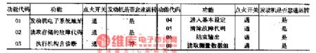
The ABS fault detecting circuit of Santana 20OOGSi
Published:2011/5/13 22:10:00 Author:Borg | Keyword: ABS, fault detecting, Santana
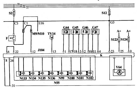
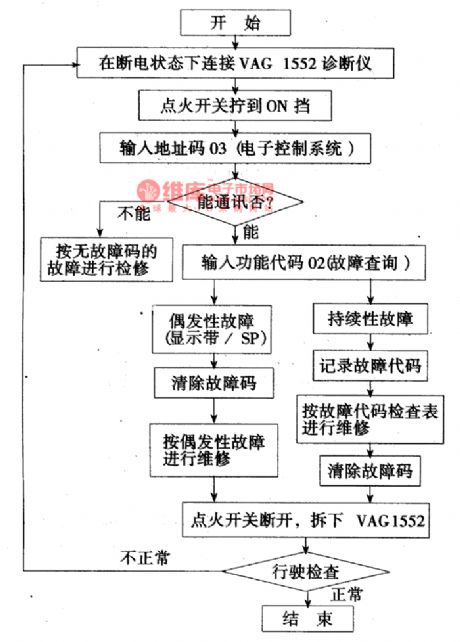
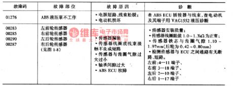
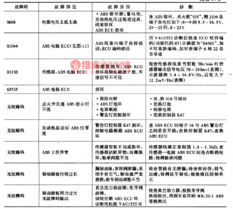
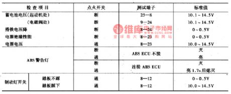
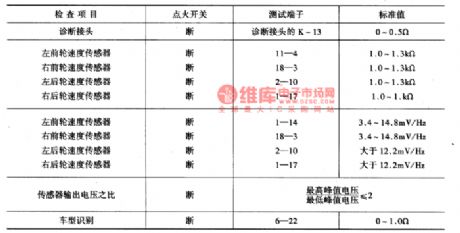
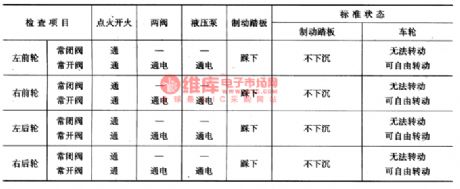
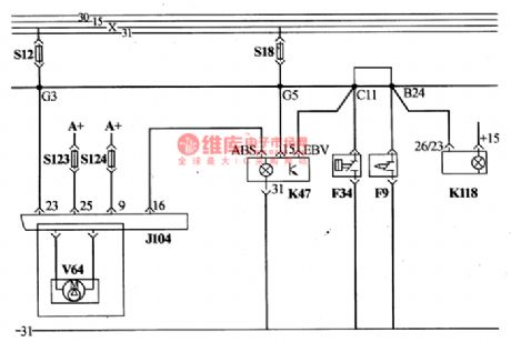
ABS computer J104 can not only control wheel brakeing automatically, but also detect its own faults. When it detect something wrong ABS, it will save it as the form of codes and light the ABS alarm lamp to remind the driver to remove it in time. In addition, there are some faults without any codes, which should be handled in regular methods. ABS fault detection can be completed with VAG1552 diagnostic apparatus,Fault codes and the removing methods are in Figure 1, and parameter detection in Figure 7, valve detection in Figure 8.
(View)
View full Circuit Diagram | Comments | Reading(716)
The starting and power supply circuit of Santana(chassis No. 3ZMP003182)
Published:2011/5/14 23:32:00 Author:Borg | Keyword: power supply, Santana
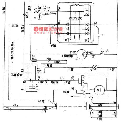
1-battery; 2-starter; 3-starting interlocking switch; 4-gear position indicator(with auto transmission); 5-fuel tank electrical pump; 5a-cold starting temperature control switch; 6-integrate alternator; 7-radio filter capacitor; 8-charging indicator; 9-power supply system relay; 10-oil assistance pump; 11-oil pump; 12-igniting switch; 13-jet resistance; 14-Ⅰjar jet; 15-jet resistance; 16-IV jar jet; 17-jet resistance; 18-Ⅱjar jet; 19-jet resistance; 20-Ⅲ jar jet (View)
View full Circuit Diagram | Comments | Reading(1281)
The wires off/on detection circuit of Santana 2000GLi
Published:2011/5/16 19:50:00 Author:Borg | Keyword: detection circuit, Santana
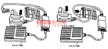
When we engage in the detection job, we should connect the box V .A Gl598 and cables V .A .G1598-9 to the connector of the wire bundles, but let the computer of line.
(1)shut down the igniting switches and pull off the connector of the engine control computer, then connect the box V .A Gl598 and cables V .A .G1598-9 to the control wires of the engine computer, by which we detect whether the circuit is off or short (computer is not connected).(2)Shut down the igniting switch and connect the box V .A Gl598 and cables V .A .G1598-9 to the engine control computer, by which we detect the voltage between the sensor and each terminal of the computer. (View)
View full Circuit Diagram | Comments | Reading(655)
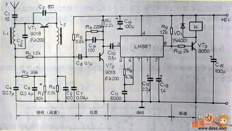
The digit display patient alarm device circuit
Published:2011/6/7 21:09:00 Author:qqtang | Keyword: digit display, patient alarm device
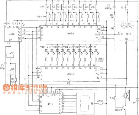
The circuit is shown in the figure, which can fulfill the dual-way signal delivering between sickrooms and duty rooms. The key switches K0~K9 and LED D0~D9 are installed in the sickroom, and the digital pipe and buzzer are fixed in the duty room. The buzzer will be still if there is no call from the sickroom, and the digital pipe is OFF. When patients press the switch K2, the buzzer in the duty room is buzzing and the pipe is indicating 2 ; at the same time, the LED in the sickroom is glowing, which shows that the patient signal has been delivered to the duty room. (View)
View full Circuit Diagram | Comments | Reading(785)
MC3357 small power FM intermediate frequency integrated circuit typical application circuit
Published:2011/5/25 20:28:00 Author:Christina | Keyword: small power, FM, intermediate frequency, integrated circuit, typical application
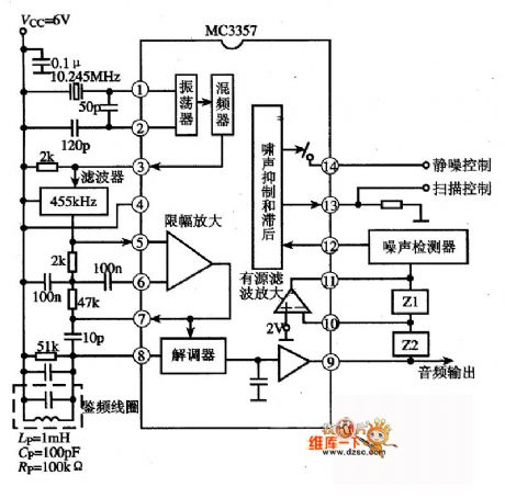
The MC3357 is designed as one kind of small power FM intermediate frequency integrated circuit that is produced by the MOTOROLA company, and it can be used in the FM duplex communication equipment's FM intermediate frequency circuit, the frequency mixer circuit, the noise suppression and lagging circuit, the active filter amplification circuit, the amplitude limit amplification circuit, the modem circuit and other subsidiary function circuits. The internal circuit block diagram and the typical application circuit which is composed of the MC3357 IC are as shown in the figure.
(View)
View full Circuit Diagram | Comments | Reading(3241)
FET FM wireless microphone circuit
Published:2011/5/26 6:52:00 Author:Christina | Keyword: FET, FM, wireless microphone
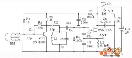
The FET FM wireless microphone circuit is as shown in this figure. This circuit uses the 2SCl000 which has the high amplification coefficient as the microphone amplification stage. The MOSFET 2SKl92A has the functions of oscillation and modulation output. The oscillation frequency is decided by the coil Ll and the parallel capacitor 6pF, by adjusting the microchip of the LI, the oscillation frequency can be changed in the range of 76MHz to 90MHz. At last, you use a ethylene line as the antenna and directly output from the FET's source electrode. In order to prevent the interference between different stages, we use the l00Ω, 47μF capacitance to form the decoupling circuit. When the circuit is working, the light-emitting diode VD turns on. The output port of the circuit do not need the buffer stage to work.
(View)
View full Circuit Diagram | Comments | Reading(1909)
Wireless hands-free telephone device circuit
Published:2011/5/30 1:45:00 Author:Christina | Keyword: Wireless, hands-free, telephone, device
The Wireless hands-free telephone device circuit is as shown:
(View)
View full Circuit Diagram | Comments | Reading(1456)
Single channel wireless remote control transceiver circuit
Published:2011/5/30 1:47:00 Author:Christina | Keyword: Single channel, wireless, remote control, transceiver
The Single channel wireless remote control transceiver circuit is as shown:
(View)
View full Circuit Diagram | Comments | Reading(1665)
Wireless hands-free telephone system circuit
Published:2011/5/20 5:38:00 Author:chopper | Keyword: Wireless, hands-free telephone
View full Circuit Diagram | Comments | Reading(1363)
UHF transmitter module CS901 composed of the SAW
Published:2011/5/13 0:44:00 Author:TaoXi | Keyword: UHF, transmitter module, SAW
UHF transmitter module CS901 is composed of the SAW (View)
View full Circuit Diagram | Comments | Reading(758)
Security wireless transmitter circuit of the adytum and the bank
Published:2011/5/13 0:43:00 Author:TaoXi | Keyword: Security wireless transmitter, adytum, bank
Security wireless transmitter circuit of the adytum and the bank (View)
View full Circuit Diagram | Comments | Reading(559)
radio transmitting typical application circuit composed of the MC2833
Published:2011/5/13 0:43:00 Author:TaoXi | Keyword: radio transmitting, typical application
radio transmitting typical application circuit is composed of the MC2833 (View)
View full Circuit Diagram | Comments | Reading(642)
radio transmitting typical application circuit composed of the MC2831
Published:2011/5/13 0:43:00 Author:TaoXi | Keyword: radio transmitting, typical application
radio transmitting typical application circuit is composed of the MC2831 (View)
View full Circuit Diagram | Comments | Reading(566)
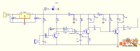
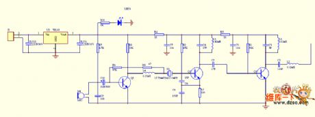
Sickroom wireless call emitting and receiving display circuit M303S/M303R
Published:2011/5/19 8:28:00 Author:TaoXi | Keyword: Sickroom, wireless call, emitting, receiving, display circuit
Data of the related components that will be used in this article:
VD5206 VD5027 M303S CD4069 CD4514 7806 LM386 HFC9301
This circuit uses the wireless transmission mode, and it uses the stable performance radio transceiver module M303S/M303R and the digital coding decoder VD5026/VD5027, it displays the bed number or the room number of the call beds, it is easy to install. The RF transmission power of this circuit is small, so it will not influence the normal working of the medical equipments. The ward wireless call system is composed of the radio call launcher and the radio receiving display which is installed in the duty room. The radio call launcher's circuit principle is as shown: (View)
View full Circuit Diagram | Comments | Reading(670)
PHILIPS 28GR6776 color TV power supply circuit
Published:2011/5/20 2:31:00 Author:Christina | Keyword: PHILIPS, color TV, power supply
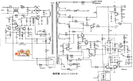
The PHILIPS 28GR6776 color TV power supply circuit is as shown:
(View)
View full Circuit Diagram | Comments | Reading(7365)
Liquid drip automatic heating alarm circuit
Published:2011/5/13 0:52:00 Author:TaoXi | Keyword: Liquid drip, automatic heating, alarm circuit
Liquid drip automatic heating alarm circuit (View)
View full Circuit Diagram | Comments | Reading(534)
The control system self-detection circuit of 2000GLi engine
Published:2011/5/16 11:08:00 Author:Borg | Keyword: control system, Santana
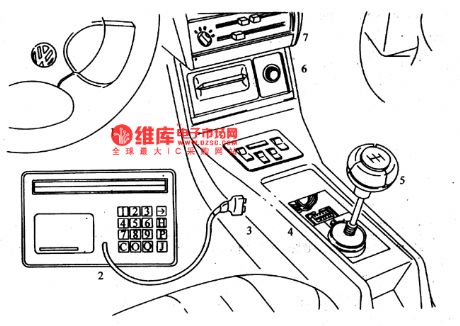
V.A.G1551 fault diagnosis equipment can not only do test on the electric spray engines of Red Flag, Jetta, Golf and Passat, but also can do the job to the engines of Santana. The car should have these conditions if we want use the equipment: the would be detected engines must have been run for a needed time, the coolant temperature need to be more than 7℃, batteries are normal, fuses are good and the ground connection of the engine is OK.
1-steer; 2-VACI551 fault diagnosis equipment; 3-the power supply plug of the equipment; 4-the outlet of the equipment.
(View)
View full Circuit Diagram | Comments | Reading(739)
Transceiver module which is composed of the remote control voice doorbell RCMlA/RCMlB
Published:2011/5/11 3:03:00 Author:TaoXi | Keyword: Transceiver module, remote control, voice doorbell
The remote control doorbell saves the wiring between the button and the doorbell, the installation position of the doorbell is very flexible and it is convenient. The voice integrated circuit can use the KD15 series of soft packaging integrated circuit. After the circuit is installed, you can use it immediately. when you are using it, you should make the receiver away from the big metal objects to avoid the influencing of the remote sensitivity. (View)
View full Circuit Diagram | Comments | Reading(570)
Digital paging systems F36-F and F36-J
Published:2011/5/11 19:20:00 Author:TaoXi | Keyword: Digital paging system
The transmission circuit:
The receiving circuit: (View)
View full Circuit Diagram | Comments | Reading(644)
| Pages:27/32 At 20212223242526272829303132 |
Circuit Categories
power supply circuit
Amplifier Circuit
Basic Circuit
LED and Light Circuit
Sensor Circuit
Signal Processing
Electrical Equipment Circuit
Control Circuit
Remote Control Circuit
A/D-D/A Converter Circuit
Audio Circuit
Measuring and Test Circuit
Communication Circuit
Computer-Related Circuit
555 Circuit
Automotive Circuit
Repairing Circuit