
Communication Circuit
Index 25
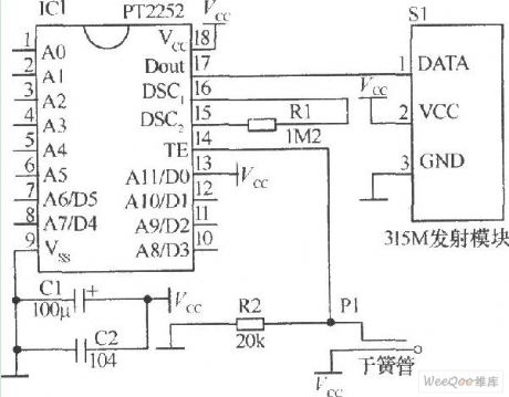
The children anti-lost reminder transceiver module composed of the RCMlA/RCMlB
Published:2011/6/14 2:56:00 Author:TaoXi | Keyword: children, anti-lost reminder, transceiver module
This circuit is composed of the transmitter and receiver, the core components are the RCM1A and RCM1B.
(View)
View full Circuit Diagram | Comments | Reading(688)
Six-channel remote control receiver circuit CS902
Published:2011/6/14 2:57:00 Author:TaoXi | Keyword: Six-channel, remote control receiver
The key components datathat will be used in this article:
CS902 CS906 SM5272-L6
(View)
View full Circuit Diagram | Comments | Reading(724)
The Sickroom wireless call emitting and receiving display circuit M303S/M303R
Published:2011/6/14 2:47:00 Author:TaoXi | Keyword: Sickroom, wireless call, emitting, receiving, display circuit
Data of the related components that will be used in this article:
VD5206 VD5027 M303S CD4069 CD4514 7806 LM386 HFC9301
This circuit uses the wireless transmission mode, and it uses the stable performance radio transceiver module M303S/M303R and the digital coding decoder VD5026/VD5027, it displays the bed number or the room number of the call beds, it is easy to install. The RF transmission power of this circuit is small, so it will not influence the normal working of the medical equipments. The ward wireless call system is composed of the radio call launcher and the radio receiving display which is installed in the duty room. The radio call launcher's circuit principle is as shown:
(View)
View full Circuit Diagram | Comments | Reading(609)
Temperature Controller (the 1st)
Published:2011/7/5 10:18:00 Author:Felicity | Keyword: Temperature Controller (the 1st)
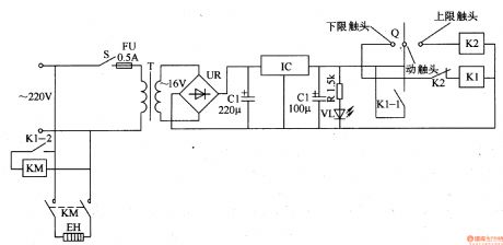
Work of the circuit
The circuit consists of power circuit and temperature detection control circuit. (It is showed in picture 8-105.)
Power circuit consists of power switch S, fuse FU, power transformer T, bridge rectifier, UR, filter capacitors Cl and C2, three-terminal voltage regulator integrated circuit IC, current-limiting resistor R and the power indicator LED VL.
Temperature detection control circuit consists of electric contact thermometers Q, relay Kl, K2, KM and AC contactor heater EH. (View)
View full Circuit Diagram | Comments | Reading(879)
Temperature Controller (the 6th)
Published:2011/7/5 10:24:00 Author:Felicity | Keyword: Temperature Controller (the 6th)
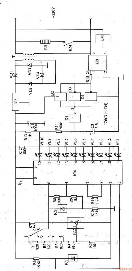
Work of the circuit
The circuit consists of power supply circuit, temperature measurement and control circuit, LED temperature indicator circuit and heater control circuit. (It is showed in picture 8-110.)
Power supply circuit consists of power transformer T, rectifier diode VDl-VD4, three-terminal voltage regulator integrated circuit IC5 and filtering capacitors Cl.
Temperature measurement and control circuit consists of temperature sensor IC lCl, temperature control selector switch S, three-terminal regulator IC lC2 and resistors Rl-R6.
LED temperature indicator circuit consists of voltage reference integrated circuit IC3, LED display driver IC lC4, resistors R8-Rl3 and light-emitting diode VLl-VLlO.
Heater control circuits consists of resistor Rl4, R15, capacitor C2, non-gate integrated circuit IC6 (D1-D4), solid state relays KN, KM and AC contactor heater EH.
(View)
View full Circuit Diagram | Comments | Reading(1190)
Temperature Controller (the 5th)
Published:2011/7/5 10:23:00 Author:Felicity | Keyword: Temperature Controller (the 5th)

Work of the circuit
The circuit consists of power circuit, temperature detection and control circuit and control implementation circuit. (It is showed in picture 8-109.)
Power circuit consists of power transformer T, rectifier diode VDl-VD4, resistors Rl and R2, the power indicator LED VLl, filter capacitors Cl and voltage regulator diode VS.
Temperature detection consists of thermistor RT, time-base integrated circuit IC, potentiometer RPl-RP4, resistors R3 and R4 and capacitors C2-C4.
Control circuit and control implementation circuit consists of relay Kl, light-emitting diodes VL2, diodes VD5, AC contactor KM and electric heater EH. (View)
View full Circuit Diagram | Comments | Reading(826)
Temperature Controller (the 4th)
Published:2011/7/5 10:22:00 Author:Felicity | Keyword: Temperature Controller (the 4th)
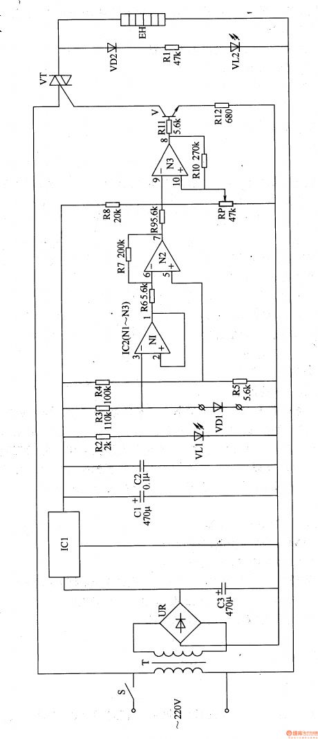
Work of the circuit
The circuit consists of power circuit, control implementation circuit and temperature detection and control circuit. (It is showed in picture 8-108.)
Power circuit consists of power switch S, the power transformer T, rectifier bridge pile UR. Filter capacitors C1-C3, three-terminal voltage regulator integrated circuit ICl, resistor R2 and the power indicator LED VLl.
Control implementation circuit consists of Resistor RlI, Rl2, transistor V and thyristor VT.
Temperature detection and control circuit consists of temperature detection diode VDl, resistors R3-RlO, operational amplifier integrated circuit IC2 (Nl-N3) and potentiometer RP. (View)
View full Circuit Diagram | Comments | Reading(737)
Temperature Controller (the 3rd)
Published:2011/7/5 10:21:00 Author:Felicity | Keyword: Temperature Controller (the 3rd)
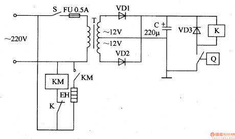
Work of the circuit
The circuit consists of power supply circuit and temperature detection circuit. (It is showed in picture 8-107.)
Power circuit consists of power switch S, fuse FU, power transformer T, a rectifier diode VDl, VD2 and filter capacitor C.
Temperature detection control circuit consists of electric contact thermometers Q, relay K, AC contactor KM, diodes VD3 and electric heater EH.
(View)
View full Circuit Diagram | Comments | Reading(813)
Temperature Controller (the 2nd)
Published:2011/7/5 10:19:00 Author:Felicity | Keyword: Temperature Controller (the 2nd)
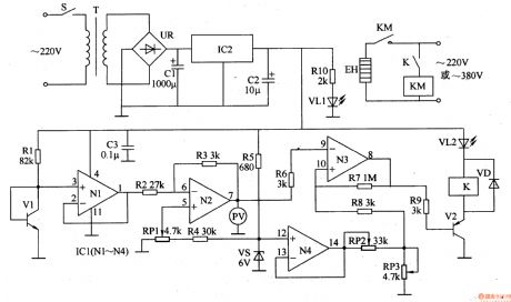
Work of the circuit
The circuit consists of power supply circuit, temperature detection circuit, reference voltage circuit, the temperature indicating circuit, voltage comparator amplifier and control implementation circuit. (It is showed in picture 8-106.)
Power supply circuit consists of power switch S, the power transformer T, bridge rectifier, UR, filter capacitors Cl, C2, three-terminal voltage regulator integrated circuit IC2, current limiting resistor RlO and power indicator LED VLl.
Temperature detection circuit consists of transistor temperature sensor Vl, resistors Rl, capacitor C3 and Nl within operational amplifier integrated circuit ICl (Nl-N4).
Reference voltage circuit consists of resistors R4, R5, R8, potentiometer RPl-RP3, voltage regulator diode VS and N4 within ICl.
The temperature indicating circuit consists of resistor R2, R3 and N2 wirhin IC1 and voltmeter PV.
Voltage comparator amplifier consists of N3 within IC1 and resistor R6 and R7.
Control implementation circuit consists of resistor R9, transistor V2, the relay K, AC contactor KM, diode light-emitting diode VD and work instructions VL2. (View)
View full Circuit Diagram | Comments | Reading(1453)
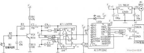
transmitter circuit with photo resistor
Published:2011/6/18 21:27:00 Author:Nancy | Keyword: photo resistor, transmitter
View full Circuit Diagram | Comments | Reading(763)
CAN bus communication circuit
Published:2011/6/20 3:17:00 Author:TaoXi | Keyword: CAN, bus, communication
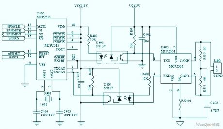
CAN bus communication circuit (View)
View full Circuit Diagram | Comments | Reading(6642)
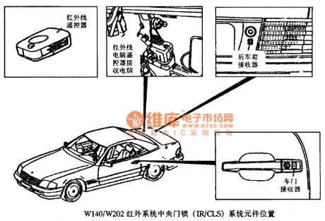
W140/W202 infrared remote control central door locking system components position circuit
Published:2011/6/13 9:47:00 Author:Christina | Keyword: infrared, remote control, central door locking system, components position
View full Circuit Diagram | Comments | Reading(4302)
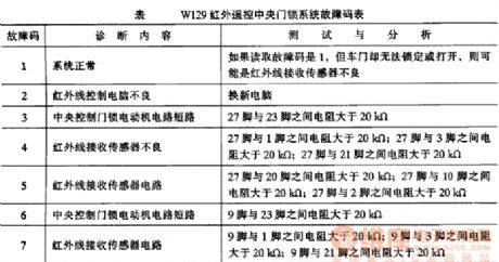
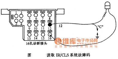
W129 infrared remote control central door locking system fault code circuit
Published:2011/6/13 9:48:00 Author:Christina | Keyword: infrared, remote control, central door locking system, fault code
View full Circuit Diagram | Comments | Reading(824)
Mercedes-Benz connection LED lamp circuit
Published:2011/6/13 9:50:00 Author:Christina | Keyword: Mercedes-Benz, connection, LED lamp
The Mercedes-Benz connection LED lamp circuit
(View)
View full Circuit Diagram | Comments | Reading(795)
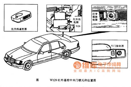
W129 infrared remote control (IR) central locking system (CLS) components position circuit
Published:2011/6/13 9:51:00 Author:Christina | Keyword: infrared, remote control, central locking system, components position, IR, CLS
View full Circuit Diagram | Comments | Reading(1139)
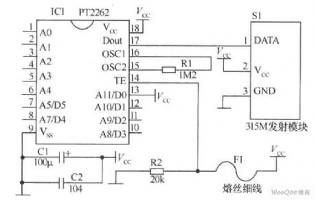
fuse wire/filament transmitter circuit
Published:2011/6/18 21:32:00 Author:Nancy | Keyword: fuse wire, filament, transmitter
View full Circuit Diagram | Comments | Reading(1100)
Magnetic induction transmitter circuit
Published:2011/6/18 21:26:00 Author:Nancy | Keyword: Magnetic induction, transmitter
View full Circuit Diagram | Comments | Reading(1245)
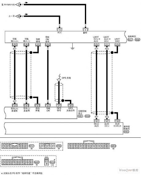
NISSAN new Teana navigation system circuit 8
Published:2011/6/18 21:16:00 Author:Nancy | Keyword: NISSAN, Teana navigation system
View full Circuit Diagram | Comments | Reading(710)
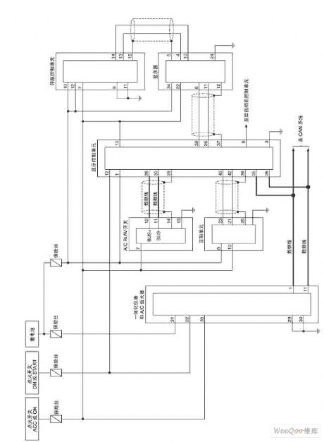
NISSAN new Teana navigation system circuit 11
Published:2011/6/18 21:21:00 Author:Nancy | Keyword: NISSAN, Teana navigation system
View full Circuit Diagram | Comments | Reading(796)
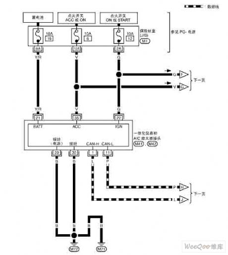
NISSAN new Teana navigation system circuit 10
Published:2011/6/18 21:20:00 Author:Nancy | Keyword: NISSAN, Teana navigation system
View full Circuit Diagram | Comments | Reading(665)
| Pages:25/32 At 20212223242526272829303132 |
Circuit Categories
power supply circuit
Amplifier Circuit
Basic Circuit
LED and Light Circuit
Sensor Circuit
Signal Processing
Electrical Equipment Circuit
Control Circuit
Remote Control Circuit
A/D-D/A Converter Circuit
Audio Circuit
Measuring and Test Circuit
Communication Circuit
Computer-Related Circuit
555 Circuit
Automotive Circuit
Repairing Circuit