
Communication Circuit
Index 20
CARRIER_CURRENT_RECEIVER
Published:2009/6/24 23:21:00 Author:May
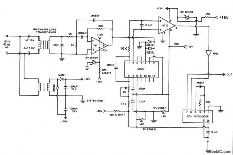
160 kHz transformer consists of a 18 x 11mm ungapped pot core (Siemens, Ferrocube, etc.), itilizing magnerics incorporated type F material wond woth 80 1/2 turns of No.35 sire for the secondary and 5 1/2 turns for the primary. This gives a turns ratio fo approximately 15 to 1. (View)
View full Circuit Diagram | Comments | Reading(0)
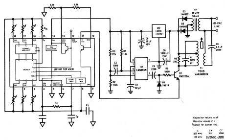
200_kHz_LINE_CARRIER_TRANSMITTER_WITH_ON_OFF_CARRIER_MODULATOR
Published:2009/6/24 23:16:00 Author:May
View full Circuit Diagram | Comments | Reading(0)
Carrier_System_Transmitter
Published:2009/6/24 23:14:00 Author:May
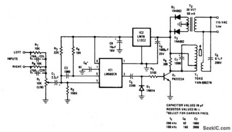
High quality, noise free, wireless FM transmitter/receiver operates over standard power lines. Complete system is suitable for high-quality transmission of speech or music, and will operate from any ac outlet anywhere on a one-acre homesite. Frequency response is 20-20, 000 Hz and THD is under 1/2%. Transmission distance along a power line is at least adequate to include all outlets in and around a suburban home and yard.Two input terminals are provided so that both left and right signals of a stereo set may be combined for mono transmission to a single remote speaker if desired. (View)
View full Circuit Diagram | Comments | Reading(0)
RECEIVER_FOR_50_kHz_FM_OPTICAL_TRANSMITTER
Published:2009/6/24 22:40:00 Author:May
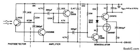
This circuit consists of a L14G2 detector, two stages of gain, and a FM demodulator. Better sensitivity can be obtained using more stages of stabilized gain with AGC. (View)
View full Circuit Diagram | Comments | Reading(0)
10_GHz_WAVEGUIDE_TRANSITION_FOR_AMATEUR_RADIO_USE
Published:2009/6/24 22:31:00 Author:May
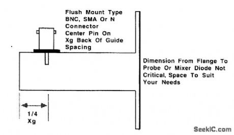
A transistor adapts the waveguide to coaxial cable or other types of transmission lines. (View)
View full Circuit Diagram | Comments | Reading(1145)
IR_TRANSMITTER
Published:2009/6/24 21:36:00 Author:May


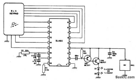
This simple infra-red transmitter, where the PPM output from pin 2 of the SL490 is fed to the base of the PNP trasmitter TR1, produces an amplified current pulse about 15,μsec wide. This pulse is further amplified by TR2 and applied to the infra-red diodes D1 and D2. (View)
View full Circuit Diagram | Comments | Reading(1816)
ULTRASONIC_SOUND_RECEIVER
Published:2009/6/24 21:35:00 Author:May
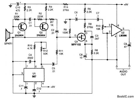
You won't be disappointed with the performance of this sensitive ultrasonic receiver. It can let you listen to bugs, bats, engines, and virtually any other source of ultrasonic sounds. This circuit uses a piezo tweeter as an ultrasonic microphone, amplifier stages Q1, Q2, and an LO using a 567IC. Q3 is a mixer that heterodynes the ultrasonic sounds down to the audible range. U2 is an amplifier that will drive a pair of headphones. (View)
View full Circuit Diagram | Comments | Reading(4509)
ULTRASONIC_cw_TRANSCEIVER
Published:2009/6/24 21:33:00 Author:May
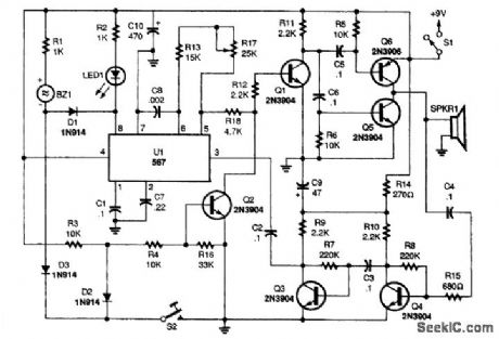
With the telegraph key at S2 up (open), the 567 PLL's input at pin 3 is coupled to the output of Q3. Transistors Q3 and Q4 are operat-ing in a high-gain, two-stage audio-amplifier circuit. The piezo speaker is coupled to the in-put of the amplifier though a 0.1-μF capacitor and a 680-Ω isolation resistor.In the receive mode, the piezo speaker oper-ates as a sensitive microphone. Ultrasonic signals travel from the microphone through the two-stage amplifier to the input of the 567, and, if the signal's frequency is within the IC's bandwidth, the LED will light and piezo-sounder BZ1 will sing out foreach dit and dah received. The receiver can be tuned to the incoming ultrasonic signal by adjust-ing R17. Of course, adjusting that potentiometer also changes the transmitter's frequency.The transmitter operates each time the S2 is closed. When the key is closed, diode D3 supplies a path to ground for BZ1, causing that sounder to produce an audible signal for each dit and dah transmitted. Also, Q2's bias is taken to ground through D2, allowing Q1 to pass the 567's square-wave signal on to the input of the power amplifier and out through the speaker. (View)
View full Circuit Diagram | Comments | Reading(0)
IR_REMOTE_CONTROL_TRANSMITTER/RECEIVER
Published:2009/6/24 21:30:00 Author:May
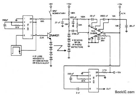
The circuit is designed to operate at 25 kHz. The data stream turns the 2N4401 hard on or off depending upon the coded state. This in turn switches the series infrared LEDs on and off. The receiver circuit consists of a three stage amplifier with photo diodes arrayed for maximum coverage of the reception area. The range of this set-up should be about 10 meters. (View)
View full Circuit Diagram | Comments | Reading(0)
LOW_COST_6_W,40_M_CW_TRANSMITTER
Published:2009/6/24 21:26:00 Author:May

L1 and L2 are wound on a 7/8 diameter form. L1 is 15 turns #22 plastic-covered wire, and L2 is 7 turns #22 plastic-covered wire. (View)
View full Circuit Diagram | Comments | Reading(0)
LOW_POWER_VHF_BEACON_TRANSMITTER
Published:2009/6/24 21:25:00 Author:May
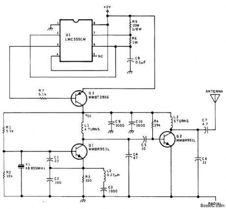
A crystal oscillator and tripler make up the low power beacon transmitter. U1 generates a pulse that keys the transmitter at a 10:1 duty cycle (100 ms on, 1 s off) to conserve battery power. This transmitter was used as a locator beacon. (View)
View full Circuit Diagram | Comments | Reading(2000)
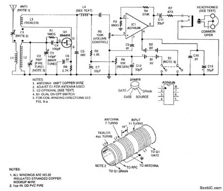
TWO_STAGE_TRF_REGENERATIVE_RECEIVER
Published:2009/6/24 4:51:00 Author:May
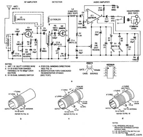
This regenerative receiver uses a tuned RE stage to improve performance. The coil in Fig. 76-24D is for the purpose of adding a second regenerative stage (RF amp). This coil is L5 in the schematic. (View)
View full Circuit Diagram | Comments | Reading(4984)
ONE_TUBE_AM_RECEIVER
Published:2009/6/24 4:33:00 Author:May
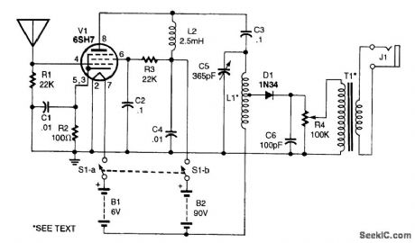
This radio uses an untuned RF stage to boost the signal voltage up to the linear portion of the crystal diode's characteristic curve. The circuit's distortion and wide bandpass and a good-quality transformer make for a great-sounding AM radio. L1 is a winding of #22 enamelled wire 2 long on a 2 diameter plastic pipe. T1 is a tube-type radio output transformer, rated at 2000 Ω to the speaker voice coil. (View)
View full Circuit Diagram | Comments | Reading(2331)
SIMPLE_RADIO_RECEIVER
Published:2009/6/24 4:31:00 Author:May
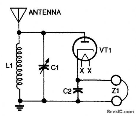
Vacuum-tube detector receiver. (View)
View full Circuit Diagram | Comments | Reading(1746)
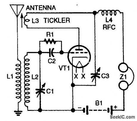
BASIC_REGENERATIVE_RECEIVER
Published:2009/6/24 4:31:00 Author:May
View full Circuit Diagram | Comments | Reading(2117)
1WWV_RECEIVER
Published:2009/6/24 4:58:00 Author:May
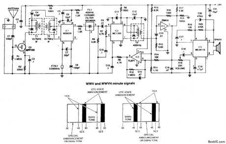
This receiver for 10-MHz WWV signals uses a 10.7-MHz FM receiver IF transformers as front-end components. It is a super-het with a 455-kHz IF frequency. By changing the front-end components 5- or 15-MHz reception could be obtained. A 3- to 6-foot antenna is usually adequate. (View)
View full Circuit Diagram | Comments | Reading(5983)
ECONOMY_SHORTWAVE_RECEIVER
Published:2009/6/24 4:51:00 Author:May
Using three transistors, this receiver covers the range of 6 to 17 MHz. Coils can be altered to change the range to a lower or higher frequency. (View)
View full Circuit Diagram | Comments | Reading(8207)
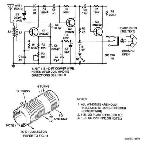
REGENERATIVE_RECEIVER_FOR_6_TO_17_MHz
Published:2009/6/24 4:49:00 Author:May
The headphones are 32-Ω stereo types.The common lead is left floating so that the two sides are in series,giving 64Ω. (View)
View full Circuit Diagram | Comments | Reading(0)
TOROIDAL_CORE_TRF_SHORTWAVE_RECEIVER
Published:2009/6/24 4:45:00 Author:May
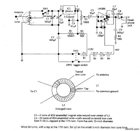
A ZN414 IC feeds an LM386 audio amplifier in this TRF circuit SW1is a band-switch,Coverageis up to 18 MHz. (View)
View full Circuit Diagram | Comments | Reading(0)
BALANCED_LINE_RECEIVER
Published:2009/6/24 4:34:00 Author:May
Unity-gain inverter U2 drives R4 (usually grounded at -Vout, equalizing currents in tinput legs, and provides a choice of balanced p-p output with a gain of R2/R1). (View)
View full Circuit Diagram | Comments | Reading(0)
| Pages:20/32 1234567891011121314151617181920Under 20 |
Circuit Categories
power supply circuit
Amplifier Circuit
Basic Circuit
LED and Light Circuit
Sensor Circuit
Signal Processing
Electrical Equipment Circuit
Control Circuit
Remote Control Circuit
A/D-D/A Converter Circuit
Audio Circuit
Measuring and Test Circuit
Communication Circuit
Computer-Related Circuit
555 Circuit
Automotive Circuit
Repairing Circuit