
Communication Circuit
Index 6
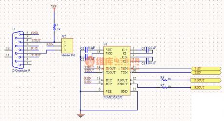
The communication conversion circuit diagram between RS232 and RS485
Published:2011/9/18 21:32:00 Author:Ecco | Keyword: communication conversion
1. The circuit diagram is the combination of the communication conversion circuit between the RS48 and RS232, RS232 and TTL level (UART) serial converter circuit. 2. This circuit is basically proven, and some RS232-TTL's speed is up to 57.6KB / s.
ADM483 requires +5V power supply, as the 78L05's efficiencyis not high. The serial get-power capacity is limited, and the output power has not reach 5V. It suggests that 485 chip uses 3.3V power supply. (View)
View full Circuit Diagram | Comments | Reading(1220)
The digital paging systems F36-F and F36-J
Published:2011/9/4 20:33:00 Author:TaoXi | Keyword: Digital paging system
The transmission circuit:
The receiving circuit:
(View)
View full Circuit Diagram | Comments | Reading(1022)
A Stable Timer Circuit Diagram of Four-Transistor
Published:2011/9/3 19:56:00 Author:Zoey | Keyword: Stable Timer Circuit , Four-Transistor
(View)
View full Circuit Diagram | Comments | Reading(1127)
Circuit diagram of power line carrier communication IC-LM1893 and its application
Published:2011/9/7 4:18:00 Author:Vicky | Keyword: power line carrier communication
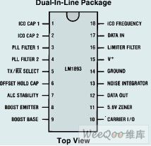
LM1893 is a power line carrier communication integrated circuit developed by National Semiconductor. It contains the whole functions of sending and receiving data. It can realize half duplex communication of serial data. It only needs few exterior components to constitute and whole power line carrier communication system, which is applicable in industrial automatic control system, building data or voice communication, house-application central control, emergency call box system in hospital, fire proofing annunciator and computer data transmitting and so on. Its main features are as follows:
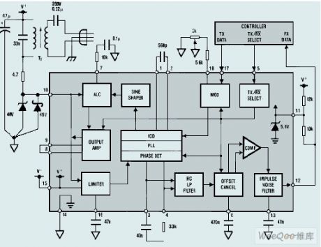
FSK anti-noise modulation technology
Pulse generator with alternative noise filtering
Data transmitting rate :up to 4.8KB
Sine wave carrier frequency to reduce radio frequency disturbance
Radio frequency rate which can be 10 times stronger
Alternative carrier frequency between 50 and 200kHz
Compatible TTL and MOS logic level
Adjustable voltage, power and level
Ability to drive all sorts of level
LM1893 working principle
(View)
View full Circuit Diagram | Comments | Reading(6846)
TDA2822 Wireless headset circuit diagram
Published:2011/8/18 1:18:00 Author:Jessie | Keyword: Wireless headset
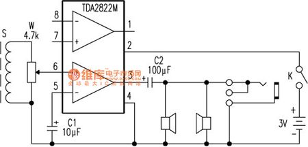
TDA2822-B Wireless headset is the voice tool for students to listen to electronic teaching pronunciation, the failure rate is higher. Because the relevant materialthat manufacturer offer is not neat,writter draw a diagram according to the real. TDA2822M is a double channel audio amplifier integrated circuit. Magnetic coil S receives the audio signal,and sends to integrated blockpin6 fromvolume potentiometer W center tap ,after internal amplification it is output by pin 3,then it isadded to two parallel headphonesby coupling capacitors C2 to makevoice. (View)
View full Circuit Diagram | Comments | Reading(5201)
RS232 serial port communication circuit
Published:2011/8/13 1:02:00 Author:qqtang | Keyword: serial port, communication circuit
View full Circuit Diagram | Comments | Reading(2131)
Voltage regulator DC-DC circuit and power supply monitor pins introduction and main features TA78L00F constant voltage regulator
Published:2011/8/17 19:40:00 Author: | Keyword: Voltage regulator, power supply monitor, main features
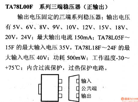
TA78L00F constant voltage regulator It can output fixed voltage, such as 5 V, 6 V , 8 V ,9 V, 10 V, 12 V, 15 V ,18 V, 20 V and 24 V. And its maximum output current is 150 mA. TA78L05F to TA78L15F have a maximum output voltage of 35 V, while TA78L18F to TA78L24F have a maximum input voltage of 40 V and the power consumption is 500mW. Its operating temperature is -30oC to +75oC. And it has over current and over heat protection circuit. (View)
View full Circuit Diagram | Comments | Reading(964)
The transceiver module of the remote control toy car circuit composed of RCMlA/RCMlB
Published:2011/8/1 22:09:00 Author:TaoXi | Keyword: Transceiver module, remote control toy car
Transceiver module of the remote control toy car circuit composed of RCMlA/RCMlB
(View)
View full Circuit Diagram | Comments | Reading(948)
The transceiver module composed of the item prevent-lost alarm RCMlA/RCMlB
Published:2011/8/1 22:09:00 Author:TaoXi | Keyword: Transceiver module, item prevent-lost alarm
The transmitter is composed of the RCM1A and the battery, the receiver is composed of the RCM1B receiving module with the double time-delay function, the high voltage generator and the alarm sound circuit.etc.
(View)
View full Circuit Diagram | Comments | Reading(1011)
The heterodyne remote control receiving circuit TDA5200
Published:2011/8/1 22:08:00 Author:TaoXi | Keyword: Heterodyne, remote control, receiving circuit
The key components that will be used in this article: HCS515 TDA5200
The TDA5200 is designed as one kind of low power consumption monolithic ASK superheterodyne receiving circuit, The working frequency range is divided into two blocks: 868~870MHz and 433~435MHz. This circuit has the features of high integration, less peripheral components and perfect function, so it is the monolithic receiving circuit that has excellent performance.
(View)
View full Circuit Diagram | Comments | Reading(1162)
The four-channel remote receiver CS902
Published:2011/8/1 22:07:00 Author:TaoXi | Keyword: Four-channel, remote receiver
The key (View)
View full Circuit Diagram | Comments | Reading(1229)
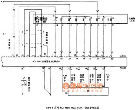
BMW5 Series AGS 560Z 88pin (E34) Transmission Circuit (the 2nd)
Published:2011/8/6 8:49:00 Author:Felicity | Keyword: BMW5 Series, 88pin (E34), Transmission Circuit, (the 2bd)
View full Circuit Diagram | Comments | Reading(1244)
BMW5 Series AGS 560Z 88pin (E34) Transmission Circuit (the 1st)
Published:2011/8/6 8:50:00 Author:Felicity | Keyword: BMW5 Series, 88pin (E34), Transmission Circuit, (the 1st)
View full Circuit Diagram | Comments | Reading(1284)
BMW5 Series A5S-310Z (E34) 88pin Transmission Circuit (the 2nd)
Published:2011/8/6 8:51:00 Author:Felicity | Keyword: BMW5 Series, 88pin, Transmission Circuit, (the 2nd)

View full Circuit Diagram | Comments | Reading(1934)
BMW5 Series A5S-310Z (E34) 88pin Transmission Circuit (the 1st)
Published:2011/8/6 8:50:00 Author:Felicity | Keyword: BMW5 Series, 88pin, Transmission Circuit, (the 1st)
View full Circuit Diagram | Comments | Reading(1257)
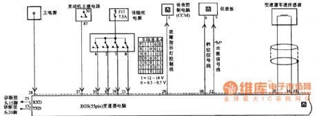
BMW5 Series EGS A4S-310R (E34) 55pin Transmission Circuit (the 2nd)
Published:2011/8/6 8:52:00 Author:Felicity | Keyword: BMW5 Series, 55pin, Transmission Circuit, (the 2nd)
View full Circuit Diagram | Comments | Reading(1676)
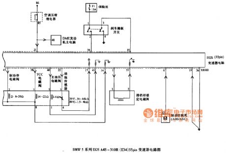
BMW5 Series EGS A4S-310R (E34) 55pin Transmission Circuit (the 1st)
Published:2011/8/6 8:52:00 Author:Felicity | Keyword: BMW5 Series, 55pin, Transmission Circuit
View full Circuit Diagram | Comments | Reading(1439)
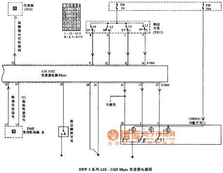
BMW3 Series A5S-310Z 88pin Transmission Circuit (the 2nd)
Published:2011/8/6 8:52:00 Author:Felicity | Keyword: BMW3 Series, 88pin, Transmission Circuit, (the 2nd)
View full Circuit Diagram | Comments | Reading(1374)
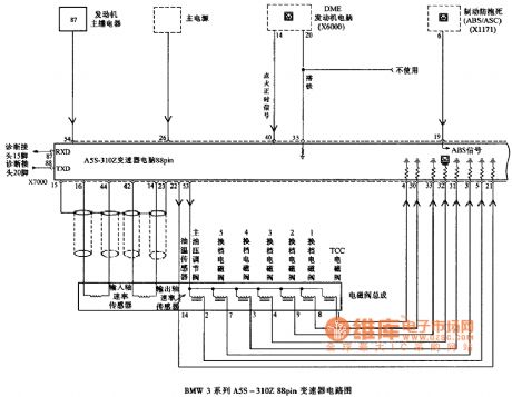
BMW3 Series A5S-310Z 88pin Transmission Circuit (the 1st)
Published:2011/8/6 8:52:00 Author:Felicity | Keyword: BMW3 Series, 88pin, Transmission Circuit, (the 1st)
View full Circuit Diagram | Comments | Reading(1662)
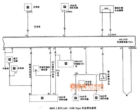
BMW3 Series A4S-310R 55pin Transmission Circuit
Published:2011/8/6 8:52:00 Author:Felicity | Keyword: BMW3 Series, 55pin, Transmission Circuit
View full Circuit Diagram | Comments | Reading(1336)
| Pages:6/32 1234567891011121314151617181920Under 20 |
Circuit Categories
power supply circuit
Amplifier Circuit
Basic Circuit
LED and Light Circuit
Sensor Circuit
Signal Processing
Electrical Equipment Circuit
Control Circuit
Remote Control Circuit
A/D-D/A Converter Circuit
Audio Circuit
Measuring and Test Circuit
Communication Circuit
Computer-Related Circuit
555 Circuit
Automotive Circuit
Repairing Circuit