
Communication Circuit
Index 2
Santana 2000 gsi type car combination instrument, radio, automatic antenna circuit diagram
Published:2014/1/22 3:43:00 Author: | Keyword: Santana 2000 gsi type car combination instrument, radio, automatic antenna circuit diagram,
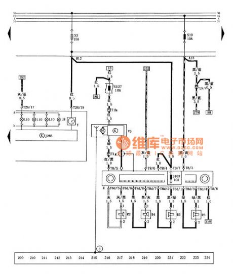
Figure combination instrument, santana 2000 gsi saloon car radios, automatic antenna circuit diagram
J285 combination instrument controller L8 - digital clock floodlight L10 - instrument lights R - cassette player R2 - left front speakers R3 - right front speakers R4 - left speaker after R5 - right rear speakers S3 - cigarette lighter, set control door locks, digital clock, after the dome light, reading lamp, suitcase light, visor light the fuse S19 (a) - a cassette player, lights, alarm control unit, the fuse (10 a) S103 - cassette player fuse (stop) (10 a) S127 - automatic antenna fuse (10 a) T1g - dashboard wiring harness and automatic antenna plug connection (1 needle, behind a cassette player) T1h - dashboard wiring harness and automatic antenna plug connection (1 needle, behind a cassette player) T8 - dashboard wire connected to the cassette player plug (8 needles, in the back of my cassette player) T8d - speaker wire connected to the cassette player plug (8 needles, in the back of my cassette player) T26 - plug connection wiring harness and combination instrument board (26 needles, on combination instrument) T29 - dashboard harness and dashboard switch harness connector (29 needle, below the combination instrument) V5 - automatic antenna Y - digital clock (3) - pick up location (near the antenna automatic car) (View)
View full Circuit Diagram | Comments | Reading(1141)
Santana 2000 gsi after car dome light, reading lamp, trunk lamp, visor light circuit diagram
Published:2014/1/22 3:38:00 Author: | Keyword: Santana 2000 gsi after car dome light, reading lamp, trunk lamp, visor light circuit diagram,
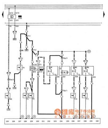

Figure santana 2000 gsi after car dome light, reading lamp, trunk lamp, visor light circuit diagram
E56 - inside the dome light lighting switch E57 - visor light switch E58 - left after reading lamp lighting switch E59 - right rear reading lamp lighting switch F2 - in the left front door dome light contact switch F3 - right inside the front door, dome light contact switch F5 - suitcase light contact switch F10 - left after reading light contact switch F11 - right rear reading light contact switch F66 - lack of coolant warning light switch J120 - cooling liquid level controller J121 - inside the dome light delay relay T1i - with door lock wire harness and tail plug connection (1 needle, behind the central circuit board) T1j - with door lock wire harness and dome light wiring harness connector (1 needle, behind the central circuit board) T2n - the engine wiring harness and dashboard wiring harness connector (2 needle, behind the central circuit board) T2p - inside the dome light wiring harness plug connection with visor lamp (2 needle, right in front of the roof) W - inside the dome light W3 - trunk floodlight W4 - visor light W5 - left after reading lamp W6 - right rear reading lamp (5) - pick up location (in the circuit board on the right side of the star grounding claw) 6 - pick up location (in the front left after a reading lamp on the roof) 7 - ground () on the posterior reading light in front of the roof pet-name ruby - its grounding - the positive cable (including dome light in the beam) (View)
View full Circuit Diagram | Comments | Reading(967)
Santana 2000 gsi type car headlights, parking lights, lights, tail lights, brake lights, nacelle, after lighting circuit diagram
Published:2014/1/21 20:07:00 Author: | Keyword: Santana 2000 gsi type car headlights, parking lights, lights, tail lights, brake lights, nacelle, after lighting circuit diagram,
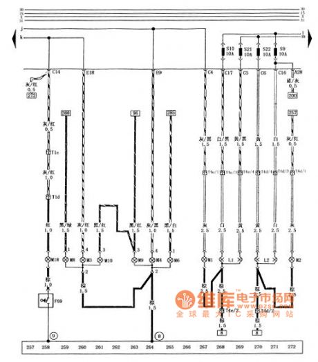
Figure of santana 2000 gsi saloon car headlights, parking lights, lights, tail lights, brake lights, nacelle, after lighting circuit diagram
F69 - nacelle light contact switch L1 - left headlamps L2 - right front headlight M1 - parking lights M3 left parking lights M2 - right - left tail lights M4 - right rear lights M6 - after the left turn signal M8 - right rear lights M9 left brake lamp M10 - right brake lamp M18 - nacelle lights integrated - right front headlight (in) the fuse (10 a) S10 - left headlamps (in) the fuse S21 (10 a) - (low), right front headlight fuse (10 a) S22 - left headlamps (low) fuse (10 a) T1c - headlamps wire connected to the engine wiring harness plug (1 needle, behind the central circuit board) T1d - the engine wiring harness and the engine compartment lighting wire connector (1 needle, in front of the wiper motor) T4d - headlamps wire connected to the right front headlight plug (4 needle, on the right front headlight) T4e - headlamps harness and left headlamps plug connection (4 needle, on the left headlights) today - ground combination (in the left rear light) on the left side of the car body earthing pet-name ruby - itself (View)
View full Circuit Diagram | Comments | Reading(990)
Santana 2000 gsi cars before the dimmer switch, alarm lamp switch, turn signal circuit diagram
Published:2014/1/21 19:57:00 Author: | Keyword: Santana 2000 gsi cars before the dimmer switch, alarm lamp switch, turn signal circuit diagram,
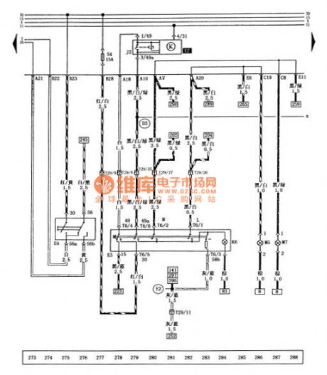


Figure santana 2000 gsi cars before the dimmer switch, alarm lamp switch, turn signal circuit diagram
E3 - alarm lamp switch E4 - dimmer switch J2 - turn signal relay K6 - alarm flash light is M5 - left front turn signal M7 - the right front turn signal S4 - alarm lights fuse T6 (15 a) - dashboard switch harness and alarming lamp switch plug connection (6 needle, on the lamp switch) T29 - dashboard harness and dashboard switch wiring harness connector (29 needle, below the combination instrument) - the positive connections (within the dashboard harness) - cable (within the dashboard switch wire) (View)
View full Circuit Diagram | Comments | Reading(773)
Turn signal switch, santana 2000 gsi saloon car parking lamp switch circuit diagram, fog light switch, dual tone horn
Published:2014/1/21 19:54:00 Author: | Keyword: Turn signal switch, santana 2000 gsi saloon car parking lamp switch circuit diagram, fog light switch, dual tone horn,
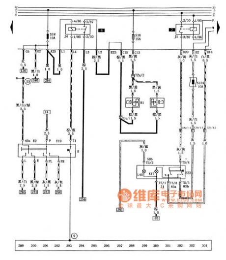

Figure of turn signal switch, santana 2000 gsi saloon car parking lamp switch circuit diagram, fog light switch, dual tone horn
E2 - turn signal switch E19 - stop lamp switch electronics - fog lamp switch H - dual tone horn switch H1 - dual tone horn J4 - horn relay J5 - fog lamps relay K17 - fog lamps light L40 - fog lamp switch lights S16 - horn fuse (15 a) S18 - the horn relay, light switch, ABS warning fuse S124 (10 a) - after the fog lights fuse (10 a) T2q - headlamps wire connected to the loudspeaker wiring harness plug (2 needle, over the loudspeaker) T5 - dashboard switch wiring harness and fog lamp switch plug connection (5 needles, in the fog lamp switch) T29 - dashboard harness and dashboard switch wiring harness connector (29 needle, below the combination instrument) pet-name ruby - its grounding - the positive connections (within the dashboard harness) (View)
View full Circuit Diagram | Comments | Reading(1193)
Santana 2000 gsi type car fog lamps, reversing lamp, license plate lamp, glove box lights, the speed sensor circuit diagram
Published:2014/1/16 22:34:00 Author: | Keyword: Santana 2000 gsi type car fog lamps, reversing lamp, license plate lamp, glove box lights, the speed sensor circuit diagram,
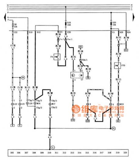
Figure of santana 2000 gsi saloon car fog lamps, reversing lamp, license plate lamp, glove box lights, the speed sensor circuit diagram
F4 - reversing lamp switch F70 - glove box light contact switch after the G7 - speed sensor L20 - fog lamps L22 - left front fog lamps L23 - right front fog lamps M16 - left back light M17 - right back light M19 - glove box lights S6 - front fog lamps fuse (15 a) S15 - reversing light fuse (10 a), speed sensor s20-40 lamp and glove box lighting the fuse (10 a) T2b - engine wiring harness and dashboard wiring harness connector (2 needle, on the left back light) T3a - the engine wiring harness and headlamps wiring harness connector (3 needles, behind the central circuit board) T3g - tail wire connected to the left back light plug (3 needles, on the left back light) T3h - tail wire connected to the right back light plug (3 needles, on the right back light) T29 - dashboard harness and dashboard switch wiring harness connector (29 needle, below the combination instrument) X - license plate lamp (5) - ground () on the circuit board on the right side of star grounding claw - the positive connections (within the headlamps harness) - grounding cables (within the tail wire) (View)
View full Circuit Diagram | Comments | Reading(1110)
Santana 2000 gsi cars before the wind window wiper, before the wind window cleaners circuit diagram
Published:2014/1/16 18:36:00 Author: | Keyword: Santana 2000 gsi cars before the wind window wiper, before the wind window cleaners circuit diagram,
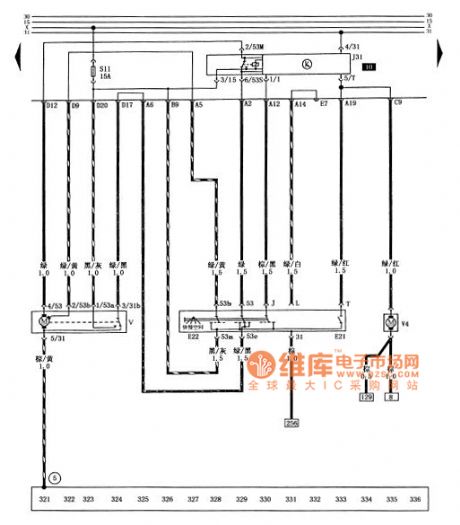
Figure santana 2000 gsi cars before the wind window wiper, before the wind window cleaners circuit diagram
E21 - the wind window cleaning pump switch E22 - before the wind window wiper switch J31 - wiper relay S11 - before the wind window wiper, cleaner fuse (15 a) V - the wind window wiper motor V4 - before the wind window cleaning pump (5) - pick up location (in the circuit board on the right side of the star grounding claw) (View)
View full Circuit Diagram | Comments | Reading(817)
Santana 2000 gsi type car electric circuit diagram window machine 1
Published:2014/1/15 18:33:00 Author: | Keyword: Santana 2000 gsi type car electric circuit diagram window machine 1,
Tusangtana 2000GSi car electric window circuit diagram
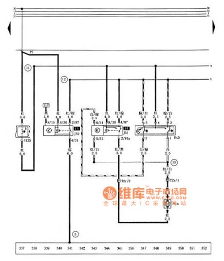
E40-shaking windows switch J51-shaking windows down automatically relay J52-shaking windows delay relay S125-electric window executive protection T2r-electric window and electric window harness plug connector (2-pin, in Left front door) V14-left front window regulator motor ⑤ - ground (on the right side of the central star circuit board ground claw) - positive cable (in the electric window harness) - connection cable (in power shake harness the windows machine) - cable (in the electric window harness) (View)
View full Circuit Diagram | Comments | Reading(959)
Santana 2000 gsi type car electric circuit diagram window machine 2
Published:2014/1/15 18:32:00 Author: | Keyword: Santana 2000 gsi type car electric circuit diagram window machine 2,
Tusangtana 2000GSi car electric window circuit diagram
E39-shaking windows safety switch (back door) E41-shaking windows switch (front left) E52-shaking windows switch (left rear) E54-shaking windows switch (right rear) T2s-electric window harness and electric window machine plug connector (2-pin, in the right front door) T3-electric window with the left rear window regulator harness plug connector (3-pin in the left rear door) T3i-electric window harness with the right rear window regulator plug connection (3-pin, in the right rear door) V15-right front window regulator motor - positive cable (in the electric window harness) - connection cable (in the electric window harness) (View)
View full Circuit Diagram | Comments | Reading(1183)
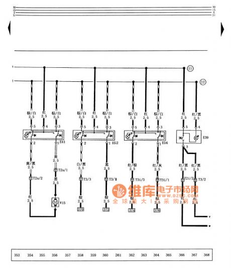
Santana 2000 gsi type car electric shake window machine, electric rearview mirror circuit diagram
Published:2014/1/15 18:30:00 Author: | Keyword: Santana 2000 gsi type car electric shake window machine, electric rearview mirror circuit diagram,
Tusangtana 2000GSi car electric window , electric mirrors schematics
E43- E48- electric mirror adjustment switch on switch electric mirrors converter E53- shaking on the left rear door window machine switch E55- right rear door window regulator switch S128- electric mirrors Fuse (3A) T2t- left rear windows shake switches and shaking windows machine motor plug connector ( 2-pin in the left rear door ) T2u- right rear power window switch and shaking windows machine motor plug connector ( 2-pin , in the right rear door ) T3j- left and left- front harness electric Mirrors plug connector ( 3-pin in the front left door ) T3k- right front door and right electric mirrors harness plug connector ( 3-pin , in the right front door ) T6a- electric mirrors harness and right front door harness plug connection ( 6-pin on the right side glove box ) T6b- electric mirrors harness and right front door harness plug connector ( 6 pin in the left center of the circuit board ) after the left rear window regulator V26- V27- motor motor Right shaking windows V33- left and down to adjust electric mirrors electric mirrors left motor V34- V35- right- left-right adjustment of the motor up and down to adjust electric mirrors electric motor V36- right- left mirror adjustment motor ⑤ - ground ( Right in the center of the circuit board side star ground claw ) ( 13 ) - cable ( in the left front door wiring harness ) (View)
View full Circuit Diagram | Comments | Reading(1003)
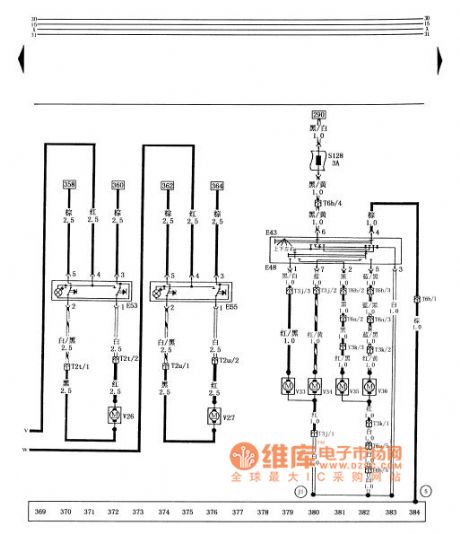
Santana 2000GSi car central control door locks, rear window defroster circuit diagram
Published:2014/1/13 18:36:00 Author: | Keyword: Santana 2000GSi car central control door locks, rear window defroster circuit diagram,
Tusangtana 2000GSi sedan centralized control door locks, rear window defroster circuit diagram
E15- rear window defroster switch J53- controlled lock controller L39- set rear window defroster switch lights rear window defroster S13- fuse (20A) T2v- left front door lock set additional control wiring harness and set central locking harness plug connector ( 2-pin in the front left door ) T2w- left front door lock set additional controls and centralized control door lock harness harness plug connector ( 2-pin in the front left door ) T2x- right front door lock set additional control wiring harness connection ( 2-pin , in the right front door ) and centralized control door lock harness plugs T2y- left rear door locks additional set of harness and left rear door attached harness plug connector ( 2-pin in the left rear door ) T2z- right rear door locks additional set Additional wiring harness and right rear door harness plug connector ( 2-pin , in the right rear door ) T2β- attach the harness and set the left rear door locks harness plug connector ( 2-pin , on the outside of the driver's seat under the carpet ) T2θ- attach the harness and set the right rear door lock harness plug connector ( 2-pin , in the passenger seat carpet outside ) T4f- dashboard switch harness with rear window defroster switch plug connector ( 4-pin on the rear window defroster switch ) T29- dashboard harness and instrument panel switch harness plug connector ( 29 -pin , at the bottom of the instrument cluster ) V30- set locks the front right , rear left set the motor V31- V32- controlled lock the right set of motor control motor Z1- lock rear window defroster ⑤ - ground ( on the right paw central star ground on the circuit board ) ⑧ - ground ( in the left rear combination lamps left the car body ) K1- cable ( in the central control door lock harness ) K2- cable ( the set Central locking wiring harness ) (View)
View full Circuit Diagram | Comments | Reading(1153)
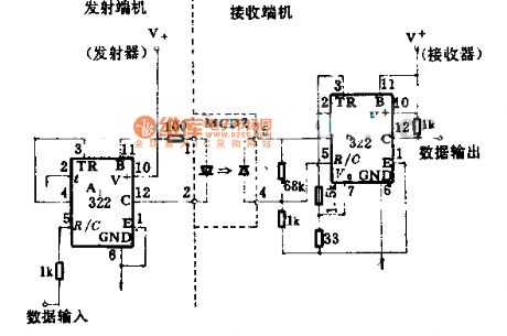
Dual channel long-term transmission circuit diagram
Published:2014/1/9 19:54:00 Author: | Keyword: Dual channel long-term transmission circuit diagram,
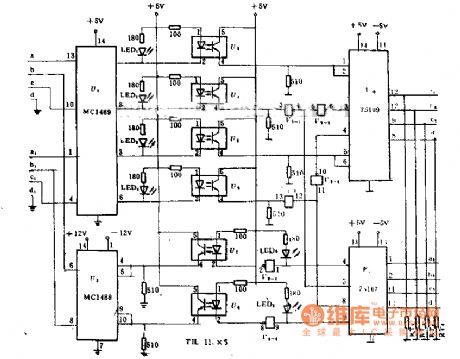
The main features of the long-term transmitter is input and output circuit adopts photoelectric isolation technology, computer and communication lines, communication lines between the terminal equipment and realized the complete electrical isolation. Can prevent the accident on line voltage, electromagnetic induction and jamming signal into the computer and terminal equipment, improve the common on sex and the stability of the computer.
This long-term transmitter circuit can work in the second half duplex or four-wire full-duplex two works. The transfer rate of 0-9, 600 - bit/s, using twisted-pair telephone transmission distance up to 10 km, at close range of computer communication, it can replace the modem.
Shown in the figure for the second line half duplex mode. At this point the first (4) (request) RS - 232 control channel to send and receive state. If it is the logic 1 is the channels for the state, or for the closed state.
If you want to work in four lines full duplex mode, as long as in the figure. A, b, c, d four thread off, and in CZ1 (1), (2), (3), (4) respectively after 1 300 Ω terminating resistance can, at this time without the RS - 232 in the first 4 request control signals. (View)
View full Circuit Diagram | Comments | Reading(905)
Photoelectric isolation type quick switch circuit diagram
Published:2014/1/9 19:46:00 Author: | Keyword: Photoelectric isolation type quick switch circuit diagram,
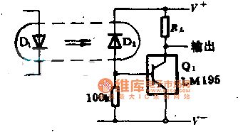
This circuit can use almost any standard of optoelectronic isolator. As long as the photoelectric diode D; Pick up to less than 20 mu A in the current, can make LM195 power transistor conduction, D2 of the cathode is power directly, and not be collector of Q1, to eliminate the influence of base - the collector capacitance. In 40 v, 1 A load case, the switch speed increased to 500 ns.
(View)
View full Circuit Diagram | Comments | Reading(723)
Optical coupling data transmission circuit diagram
Published:2014/1/8 20:03:00 Author: | Keyword: Optical coupling data transmission circuit diagram,
Optical coupling data transmission circuit diagram
(View)
View full Circuit Diagram | Comments | Reading(790)
With isolation performance data coupling circuit diagram of electric power
Published:2014/1/8 19:58:00 Author: | Keyword: With isolation performance data coupling circuit diagram of electric power,

With isolation performance data coupling circuit diagram of electric power
(View)
View full Circuit Diagram | Comments | Reading(722)
10 megabit fiber optic data line circuit diagram
Published:2014/1/8 19:49:00 Author: | Keyword: 10 megabit fiber optic data line circuit diagram,
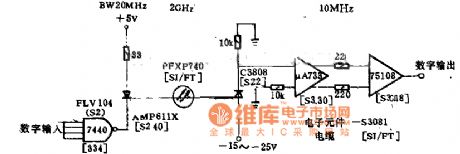
10 megabit fiber optic data line circuit diagram
(View)
View full Circuit Diagram | Comments | Reading(896)
BMW 20 pin diagnosis in engine compartment on the left side of the circuit diagram
Published:2014/1/7 19:56:00 Author: | Keyword: BMW 20 pin diagnosis in engine compartment on the left side of the circuit diagram,

BMW 20 pin diagnosis in engine compartment on the left side of the circuit diagram
(View)
View full Circuit Diagram | Comments | Reading(838)
BMW series engine fault codes before 1988 Diagram
Published:2014/1/7 19:55:00 Author: | Keyword: BMW series engine fault codes before 1988 Diagram,
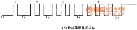
BMW series engine fault codes before 1988 Diagram (View)
View full Circuit Diagram | Comments | Reading(775)
BMW 3,5,7 series engine fault codes for the two yards or three yards circuit diagram of a waveform
Published:2014/1/7 19:53:00 Author: | Keyword: BMW 3,5,7 series engine fault codes for the two yards or three yards circuit diagram of a waveform,
BMW 3,5,7 series engine fault codes for the two yards or three yards circuit diagram of a waveform
(View)
View full Circuit Diagram | Comments | Reading(830)
BMW 3, 5, 7 series engine fault codes for two or three yards waveform diagram 2
Published:2014/1/7 19:52:00 Author: | Keyword: BMW 3, 5, 7 series engine fault codes for two or three yards waveform diagram 2,

BMW 3, 5, 7 series engine fault codes for two or three yards waveform diagram 2
(View)
View full Circuit Diagram | Comments | Reading(796)
| Pages:2/32 1234567891011121314151617181920Under 20 |
Circuit Categories
power supply circuit
Amplifier Circuit
Basic Circuit
LED and Light Circuit
Sensor Circuit
Signal Processing
Electrical Equipment Circuit
Control Circuit
Remote Control Circuit
A/D-D/A Converter Circuit
Audio Circuit
Measuring and Test Circuit
Communication Circuit
Computer-Related Circuit
555 Circuit
Automotive Circuit
Repairing Circuit