
Communication Circuit
Index 19
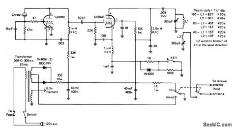
ONE_TUBE,10_WATT_CW_TRANSMITTER
Published:2009/6/30 3:05:00 Author:May
View full Circuit Diagram | Comments | Reading(1635)
1_2_MHz_BROADCAST_TRANSMITTER
Published:2009/6/30 3:02:00 Author:May
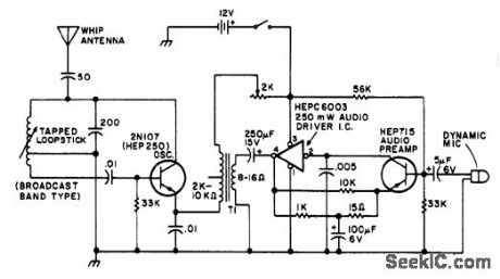
T1 is a low impedance output transformer 5000-8 ohms. (View)
View full Circuit Diagram | Comments | Reading(1093)
12_V_TO__11_V_WITH_TRANSISTORS
Published:2009/6/30 2:09:00 Author:May
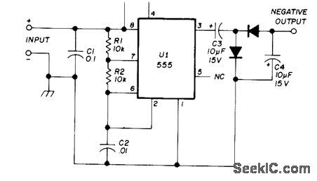
Bipolar inverter and rectifier together provide -11 V from 12-V auto battery for operdting highthreshold MOS logic of portable or automotive equipment. Transistor and diode types are not critical. Multivibrator draws only 1.2 mA from battery on standby and supplies 12 mA from negative output terminal.—B. Fette, Inexpensive Inverters Generate VGG for Portable MOS Applications, EDN|EEE Magazine, Dec.15, 1971, p 51. (View)
View full Circuit Diagram | Comments | Reading(959)
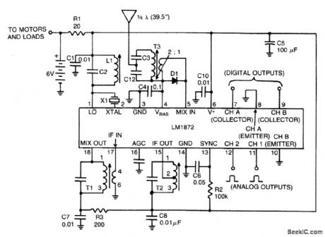
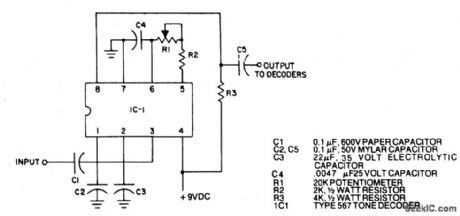
RADIO_CONTROL_RECEIVER_DECODER
Published:2009/6/29 4:03:00 Author:May
View full Circuit Diagram | Comments | Reading(1490)
12_W_WITH_BOOSTER_TRANSISTORS
Published:2009/6/29 2:40:00 Author:May
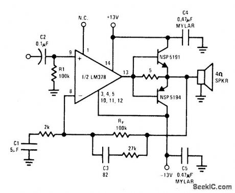
At signal input levels below 20 mW、National LM378 opamp suppliesload directly through 5-ohm resistor up to current peaks of about 100 mA。Above this level、booster transistors are biased on by load current through same resistor to increase output power, Transistors and opampmust have adequate heatsinks,-″Audio Hand-book″ National Semiconductor、Santa Clara、 CA,1977、p 442-4-43。 (View)
View full Circuit Diagram | Comments | Reading(1575)
HIGH_GAIN_IC_WITH_TRANSISTOR
Published:2009/6/28 23:30:00 Author:May
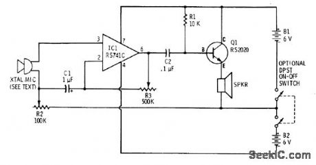
High Inputimpedance of RS741C opamp permits use withany general-purpose crystal microphone R2 is volume control,and R3 controls gain and frequency response of IC Power transistor stagedrives loudspeaker directly without outputtransformer、-F M、Mims,″Integrated Circuit Proiects、vol,6、″Radio Shack,Fort Worth,TX,'1977 p 79-88 (View)
View full Circuit Diagram | Comments | Reading(1443)
10_kHz_SFERICS_RECEIVER
Published:2009/6/28 22:42:00 Author:May
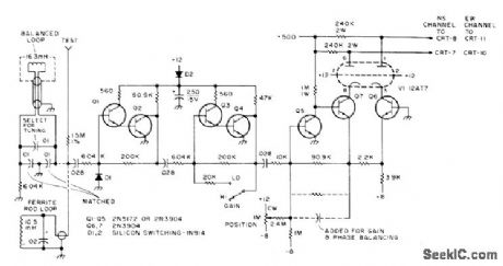
Developed to measure direction and strength of atmospheric electromagnetic radiation(sferics)associated with severe weather conditions,for detection and tracking of tomadoes. Signals from crossed loop antennas feed deflection amplifier of CRO.Article covers problems involved and gives circuit for sense amplifier that resolves 180°ambiguity in oscilloscope pattern,-R W Fergus、A Ham Radio Severe Weather Warning Net,73 Magazine.Sept,1974、p 27-30、32、34-36、and 38-39 (View)
View full Circuit Diagram | Comments | Reading(2772)
INEXPENSIVE_ISOLATION_TRANSFORMERIMPROMPTU_SETUP
Published:2009/6/26 5:17:00 Author:May
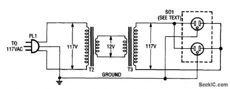
Using two 12-V filament or power transformers, an impromptu isolation transformer can be made for low-power(under 50 W) use in testing or servicing. SO1 is an ordinary, duplex ac receptable. Use heavy-wire connections between the 12-V windings because several amperes can flow. (View)
View full Circuit Diagram | Comments | Reading(0)
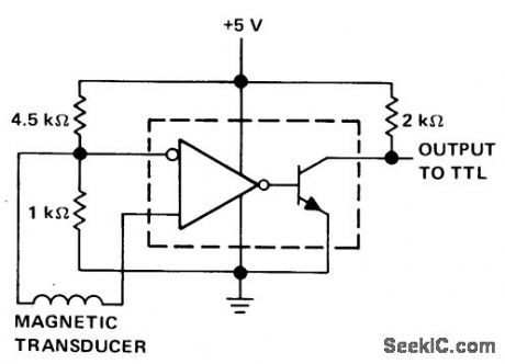
CMOS_LINE_RECEIVER
Published:2009/6/26 3:45:00 Author:May
The trip point is set half way between the supplies by R1 and R2; R3 provides over 200 mV of hysteresis to increase noise immunity.Maximum frequency of operation is about 300 kHz. If response to TTL levels is desired, change R2 to 39 K. The trip point is now cen-tered at 1.4 V. (View)
View full Circuit Diagram | Comments | Reading(0)
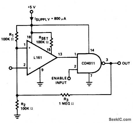
DETECTOR_FOR__MAGNETIC_TRANSDUCER___
Published:2009/6/25 23:22:00 Author:May
View full Circuit Diagram | Comments | Reading(0)
FAR_FIELD_TRANSMITTER
Published:2009/6/25 23:14:00 Author:May
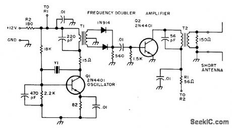
Provides far-field signal source for tuning Yagi and other beam antennas used on amateur radio frequencies.Q1 is Pierce oscillator operating in fundamental mode of 7.06-MHz crystal to permit field-strength measurements at 14.12, 21.18, and 28.24 MHz for 20-, 15-, and 10-meter bands. An-tenna uses two 5-foot lengths of wire con-nected as dipole. T1 is Amidon core 750-2 with 22 tums on primary and 20 tums center-tapped on secondary. T2 is same core with 22-tum pri-mary and 5-tum secondary.-G. Hinkle, Closed Loop Antenna Tuning, 73Magazine, May 1976, p32-33. (View)
View full Circuit Diagram | Comments | Reading(1052)
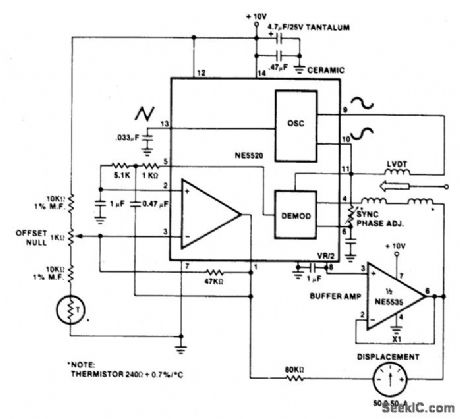
LINEAR_VARIABLE_DIFFERENTIAL_TRANSFORMER(LVDT)MEASURING_GAUGE
Published:2009/6/25 20:52:00 Author:May
View full Circuit Diagram | Comments | Reading(0)
FM_PRM_OPTICAL_TRANSMITTER
Published:2009/6/24 23:53:00 Author:May
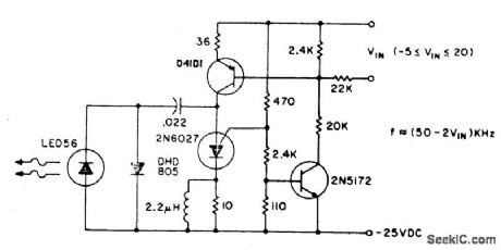
The basic circuit can be operated at 80 kHz and is limited by the PUT capacitor combi-nation. 60 kHz is the maximum modulation fre-quency. The pulse repetition rate is a linear function of VIN, the modulating voltage. Lenses or reflectors minimizes stray light noise effects. Greater output can be obtained by using a larger capacitor, which also gives a lower operating frequency, or using a higher power output IRED such as the F5D1. Average power consumption of the transmitter circuit is less than 3 watts. (View)
View full Circuit Diagram | Comments | Reading(1035)
NULL_DETECTOR
Published:2009/6/24 23:45:00 Author:May
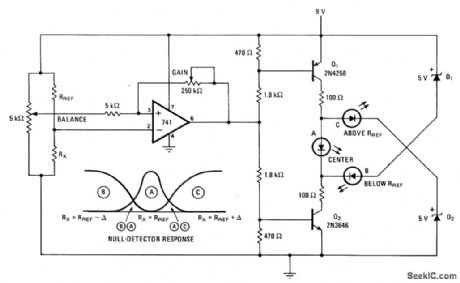
Null detector uses simple LED readout to indicate iftest resistor Rx is below, equal to, or greater than test resistance Rref. If Rx = Rref, the 741 output sits at midpoint value of 4.5 volts and LED A lights. Otherwise, the output of the 741 turns off one transistor and diverts current from the other transistor through B or C, depenging on the polarity of the input voltage difference.Null-detector resoinse is illustrated. (View)
View full Circuit Diagram | Comments | Reading(0)
OPTICAL_RECEIVER
Published:2009/6/24 23:44:00 Author:May
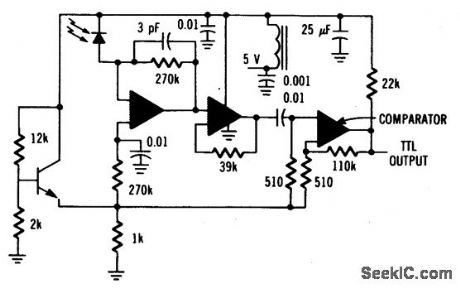
The MFOD1100 PIN diode requires shielding from emi. (View)
View full Circuit Diagram | Comments | Reading(0)
OPTICAL_TRANSMITTER
Published:2009/6/24 23:43:00 Author:May
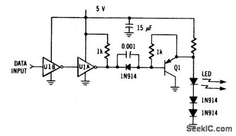
Driver circuit uses an MC74LS04 and one discrete transistor. The circuit can drive the LED (MFOE1200) at up to 1 Mbps data rate. (View)
View full Circuit Diagram | Comments | Reading(0)
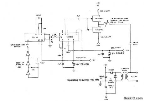
IC_CARRIER_CURRENT_RECEIVER
Published:2009/6/24 23:31:00 Author:May
View full Circuit Diagram | Comments | Reading(975)
IC_CARRIER_CURRENT_TRANSMITTER
Published:2009/6/24 23:29:00 Author:May

View full Circuit Diagram | Comments | Reading(0)
CARRIER_CURRENT_TRANSMITTER_1
Published:2009/6/24 23:25:00 Author:May
View full Circuit Diagram | Comments | Reading(0)
CARRIER_CURRENT_TRANSMITTER
Published:2009/6/24 23:24:00 Author:May
View full Circuit Diagram | Comments | Reading(0)
| Pages:19/32 1234567891011121314151617181920Under 20 |
Circuit Categories
power supply circuit
Amplifier Circuit
Basic Circuit
LED and Light Circuit
Sensor Circuit
Signal Processing
Electrical Equipment Circuit
Control Circuit
Remote Control Circuit
A/D-D/A Converter Circuit
Audio Circuit
Measuring and Test Circuit
Communication Circuit
Computer-Related Circuit
555 Circuit
Automotive Circuit
Repairing Circuit