
Communication Circuit
Index 13
PPM_DEMAODULATOR
Published:2009/7/19 22:20:00 Author:Jessie
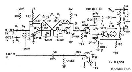
Input is modified two-input semiconductor diode and sate, driving bistable mvbr, modified bootstrap sweep, and filter to give d-c data voltage output.-L. Weisman, Telemetry Demodulator Using Modified And Gate, Electronics, 32:8, p 54-57. (View)
View full Circuit Diagram | Comments | Reading(1061)
100_MC_LINK_TRANSMITTER
Published:2009/7/19 22:19:00 Author:Jessie
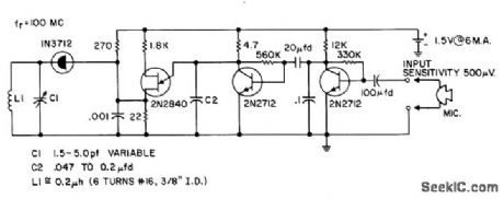
Signal picked up by microphone is amplified by first 2N2712, which turns off second 2N2712, allowing C1 to charge up and ire 2N2840 unijunction oscillator, producing pulse that modulates tunnel-diode transmitter.- Transistor Manual, Seventh Edition, General Electric Co., 1964, p 362. (View)
View full Circuit Diagram | Comments | Reading(1799)
PCM_TELEMETRY_MULTIPLEXER
Published:2009/7/19 22:18:00 Author:Jessie

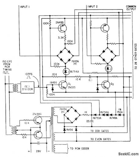
Permits gate-switching transistors Q1-Q2 to double in ring counter and control sequencing. Uses four-diode bridge for each gate, with single transformer-coupled looting voltage source switched to each gate in succession by two. transistor switching gate.-R. C. Onstad, Solid-State 30-Channel Multiplexor Designed for Minimum Components, Electronics, 34:40, p 77-79. (View)
View full Circuit Diagram | Comments | Reading(1376)
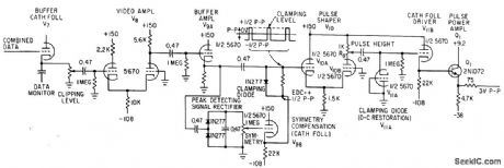
PDM_KEYER
Published:2009/7/19 22:14:00 Author:Jessie
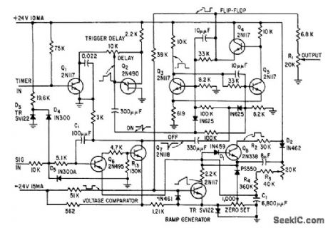
High linearity, low crosstalk and jitter, and high effective input impedance are provided by transistor pulse-duration-modulation keyer. Circuit includes bi-stable flip-flop, linear ramp generator, and voltage comparator. Output pulse widths vary with signal amplitude.-D. A. Williams Jr., Transistors Ruggedize Airborne Telemetry Keyer, Electronics, 31:37, p 81-83. (View)
View full Circuit Diagram | Comments | Reading(1344)
PULSE_COMMAND_MONITOR
Published:2009/7/19 22:06:00 Author:Jessie
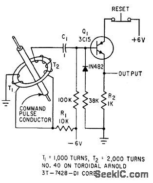
Toroid in control electrode circuit of solid-state thyratron Q1 triggers circuit on when command pulse passes through insulated conductor, without affecting command circuit for such critical functions as arming of missile.-R. C. Wright, Collecting Data from Live Missiles in Flight, Electronics, 34:12, p 46-49. (View)
View full Circuit Diagram | Comments | Reading(1419)
ENERGY_LOSS_TELESCOPE
Published:2009/7/19 22:05:00 Author:Jessie
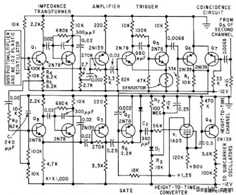
Uses sensistors to help compensate for temperature effects. Circult normally employs two identical channels for the two multiplier phototubes, to drive coincidence circuit that feeds height-to-time converter.-D. Enemark, Balloon-Borne Circuits Sort High. Altitude Cosmic Rays, Electronics, 32:35, p 52-55. (View)
View full Circuit Diagram | Comments | Reading(985)
FOOTBALL_HELMET_TRANSMITTER
Published:2009/7/19 22:04:00 Author:Jessie
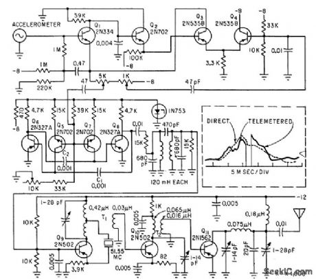
Impact data sensed by accelerometer in helmet is, transmitted to sideline receiver by f-m/f trans-miller. Use of subcarrier oscillator makes transmitter more immune to shock and vibration than with conventional main-channel oscillator.-J. S. Aagaard and J. L. DuBois, Telemetering impact Data from the Football Field, Electronics, 35:14, p 46-47. (View)
View full Circuit Diagram | Comments | Reading(1465)
FOUR_CHANNEL_DISCRIMINATOR
Published:2009/7/19 22:02:00 Author:Jessie
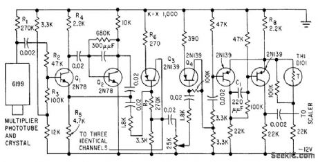
Common amplifier and four individual amplifiers drive triggers for four channels of sealers. Common amplifier supplies 7 v on common bus from Q3 to four potentiometers, settings of which determine discrimination point for each channel.-D. Enemark, Balloon-Borne Circuits Sort High-Altitude Cosmic Rays, Electronics, 32:35, p 52-55. (View)
View full Circuit Diagram | Comments | Reading(917)
ELECTROMETER
Published:2009/7/19 21:58:00 Author:Jessie
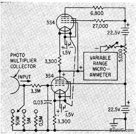
Amplifies output of photo-multiplier that responds to degree of fluorescence, which in turn is proportional to radiation received by glass dosimetry needle implanted in body of person undergoing radiation treatment.-S. J. Malsky et al, Measuring Radiation Within Human Body, Electronics, 33:12, p 74-75. (View)
View full Circuit Diagram | Comments | Reading(0)
LOGARITHMIC_AMPLIFIER_FOR_05_TO_6_V_D_C
Published:2009/7/19 21:57:00 Author:Jessie

Uses operational amplifer and function generator principle lo compress detector signal levels to values within range of telemetering system.-S. Chase, Jr. and F. Schwarz, Mariner II Instrumentation: What Will It See on Venus ?, Electronics, 35:50, p 42-45. (View)
View full Circuit Diagram | Comments | Reading(1173)
F_M_F_M_TRANSMITTER
Published:2009/7/19 21:56:00 Author:Jessie
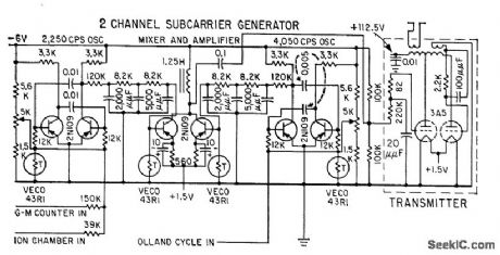
Output power is 0.5 w at 95 Mc, and range is 400 miles. Provides two channels.-L. E. Peterson, R. L. Howard, and J. R. Winckler, Balloon Gas Monitors Cosmic Radiation, Electronics, 31:45, p 76-79. (View)
View full Circuit Diagram | Comments | Reading(1101)
TWO_CHANNEL_DIVERSITY_COMBINER
Published:2009/7/19 21:55:00 Author:Jessie
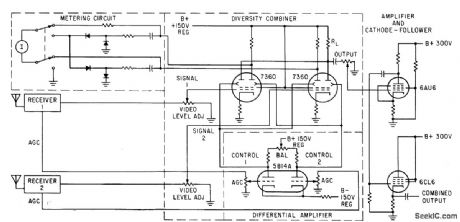
Beam-deflection lubes provide ratio-squared combining of two telemetry receiving channels, to counteract fading signals from tumbling or spinning spacecraft missile. Video signals go directly to control grids of type 7360 defiection tubes, while control voltages from receivers are applied to the respective deflection electrodes through differential amplifier,-V,A.Rafner, Telemetry Diversity Combiner Uses Beam Deflection Technique, Electronics, 35:4, p 42-43.
(View)
View full Circuit Diagram | Comments | Reading(1296)
RESISTANCE_CONTROLLED_SUBCARRIER_OSCILLATOR
Published:2009/7/19 22:30:00 Author:Jessie
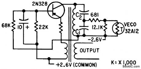
Required 7.5% frequency deviation is obtained with ratio of 1.5 for C1/C2.-H. L. Richter et al., Instrumenting the Explorer I Sotellite, Electronics, 32:6, p 39-43. (View)
View full Circuit Diagram | Comments | Reading(1081)
CURRENT_CONTROLLED_SUBCARRIER_OSCILLATOR
Published:2009/7/19 22:29:00 Author:Jessie
Uses time-controlled reactance modulation. Operating frequency is altered by in. troducing alternating current having same frequency but 90° out of phase with oscillator voltage. Frequency shift thus produced is proportional to amount of additional current fed into tuned circuit.-H. L. Richler et al., Instrumenting the Explorer I Satellite, Electronics, 32:6, p 39-43. (View)
View full Circuit Diagram | Comments | Reading(1276)
PROJECTILE_NOSE_PRESSURE_TELEMETER
Published:2009/7/19 22:28:00 Author:Jessie
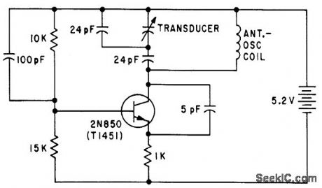
Variable-capacitance pressure transducer modulates 150-Mc carrier for telemetering stagnation pressure at nose of projectile during flight. Antenna-oscillator coil has four turns of No. 24 AWG wire, 0.16 inch inside diameter.-O. H. Bock and P. L. Clemens, Aerodynamic Measurements in a Hypervelocity Gun Range, Electronics, 34:44, p 33-37. (View)
View full Circuit Diagram | Comments | Reading(1362)
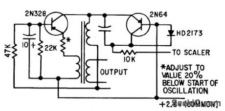
FIVE_FREQUENCY__OSCI_LLATOR
Published:2009/7/19 22:28:00 Author:Jessie
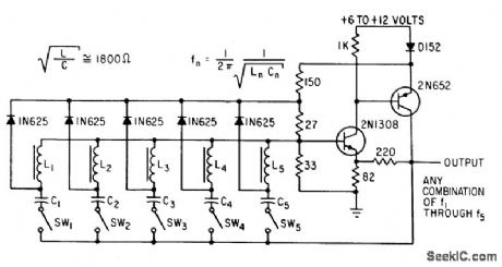
Two-transistor circuit generates up to five different tones simultaneously for five-bit parallel encoder for telemetry. Starting transients ore built up in individual series-tank circuits. Amplitude of oscillation stabilizes al value where energy from negative-resistance source equals energy lost in tanks.-R. Stapelfeldt, Multitone Oscillators-New Source of Simultaneous Frequencies, Electronics, 36:1, p 86-87. (View)
View full Circuit Diagram | Comments | Reading(4163)
PULSE_RESHAPER
Published:2009/7/19 22:33:00 Author:Jessie
Serves as output amplifier for pcm and pdm signals from diversity combiner circuit. Over-amplification and dipping stages give fast rise and decay time without risk of false triggering.-W. Casson and R. C. Robinson, Versatile Diversity Combiner Handles Most Missile-Range Signals, Electronics, 35:44, p 40-43.
(View)
View full Circuit Diagram | Comments | Reading(888)
40000_BITS_PER_SEC_OVER_PHONE_LINE
Published:2009/7/19 22:33:00 Author:Jessie
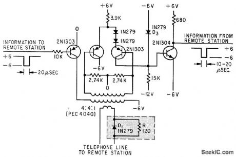
For interconnecting computers, one-transistor line driver und wave shaper permit transmitting 40,000 bits per second up lo half a mile over standard voice-grade phone lines. Three-transistor line receiver and pulse slicer receive data.-R. M. Lee, Speeding Digital Data Over Phone Lines, Electronics, 36:39, p 30-31.
(View)
View full Circuit Diagram | Comments | Reading(1403)
OPTICAL_LASER_RECEIVER
Published:2009/7/10 2:01:00 Author:May

Using a single 741 op amp, a photodiode sensor, and an LM386, this simple receiver operates from a 9-V battery. The circuit will drive a pair of earphones or a small speaker. (View)
View full Circuit Diagram | Comments | Reading(2140)
LIGHT_TRANSMTTER
Published:2009/7/10 1:59:00 Author:May
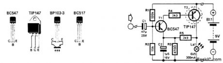
This circuit modulates the current through a lamp filament. Use a low-voltage lamp with a thin, straight filament. They have a fast response to ftlament voltage variations. dc is applied to bias the fila-ment that is on, and the audio is superimposed. A BC457 drives a TIP147, which modulates the filament current. (View)
View full Circuit Diagram | Comments | Reading(3927)
| Pages:13/32 1234567891011121314151617181920Under 20 |
Circuit Categories
power supply circuit
Amplifier Circuit
Basic Circuit
LED and Light Circuit
Sensor Circuit
Signal Processing
Electrical Equipment Circuit
Control Circuit
Remote Control Circuit
A/D-D/A Converter Circuit
Audio Circuit
Measuring and Test Circuit
Communication Circuit
Computer-Related Circuit
555 Circuit
Automotive Circuit
Repairing Circuit