
Communication Circuit
Index 24
SIMPLE_DIRECT_CONVERSION_RECEIVER_FOR_160_TO_20_M
Published:2009/6/17 22:02:00 Author:May
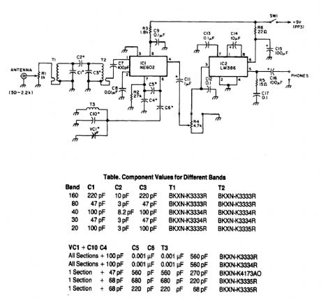
Note that T1 and T2 are TOKO, including part numbers for the coils T1 and T2. The direct-con-version receiver shown uses a double-tuned input network made from readily available TOKO coils. IC1, an NE602, acts as a VFO and mixer, with the output being an IF frequency in the audio range. IC2 is an audio amplifier, R4 is a volume control. (View)
View full Circuit Diagram | Comments | Reading(3225)
SAA3006 general infrared remote control launch circuit
Published:2011/7/20 7:38:00 Author:Christina | Keyword: general, infrared, remote control, launch circuit
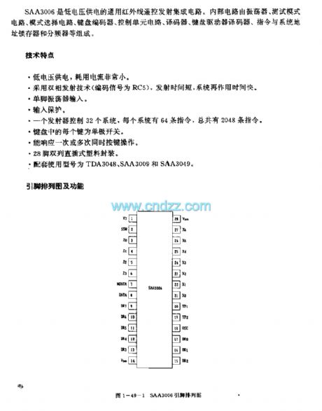
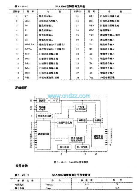
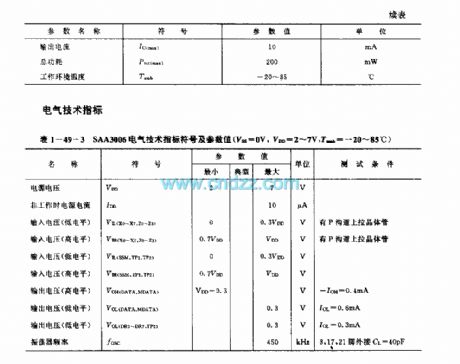
The SAA3006 is designed as one kind of low voltage power supply general general infrared remote control launch circuit. The internal circuit is composed of the oscillator, the test mode circuit, the mode selection circuit, the keyboard encoder, the control unit circuit, the decoder, the keyboard driver decoder, the instruction and system address latch and the frequency divider.
Features
Low voltage power supply, the power consumption is very small,It uses the dual-phase launch technology, the launch time is short,The single pin oscillator input,the input protection,Every launcher controls 32 systems, every system has 64 instructions,Every button of the keyboard is the single-pole switch,28-pin dual-row DIP plastic package,The matching model are TDA3048, SAA3009 and SAA3049.
(View)
View full Circuit Diagram | Comments | Reading(1375)
YN9101 general remote control receiving circuit (dual-tone multi-frequency signal receiving circuit)
Published:2011/7/21 4:02:00 Author:TaoXi | Keyword: general, remote control, receiving circuit, dual-tone, multi-frequency, signal receiving
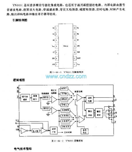
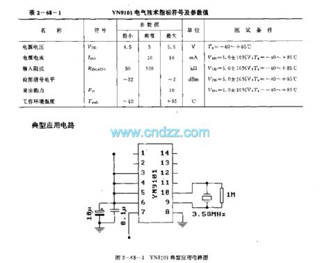
The YN9101 is designed as one kind of dual-tone multi-frequency signal receiving circuit that also can be used in the general remote control receiving circuit. The internal circuit is composed of the dial tone filter circuit, the preamplifier circuit, the bandpass filter, the zero cross detector, the amplitude detector, the timing circuit, the clock generator circuit, the output decoding circuit and the output register.
(View)
View full Circuit Diagram | Comments | Reading(1615)
(TV) infrared remote control receiving circuit
Published:2011/7/21 4:10:00 Author:TaoXi | Keyword: TV, infrared, remote control, receiving circuit
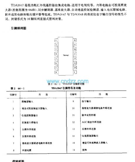
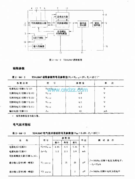
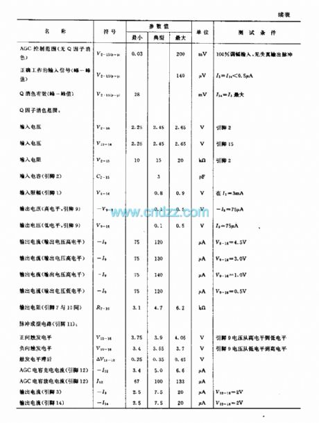
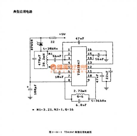
The TDA3047 is designed as one kind of low power consumption infrared remote control receiving circuit that can be used in the TV application. The internal circuit is composed of the controllable high-frequency amplifier (the control range is 66dB), the synchronous demodulator, the reference amplifier, the automatic gain control detector, the input voltage limiter circuit, the pulse shaping circuit and the output buffer. The difference of the TDA3047 and TDA3048 is the polarity of the output signal. This device is in the 16-pin dual-row DIP plastic package.
(View)
View full Circuit Diagram | Comments | Reading(1676)
TDA3048 (TV) infrared remote control receiving circuit
Published:2011/7/21 4:13:00 Author:TaoXi | Keyword: TV, infrared, remote control, receiving circuit
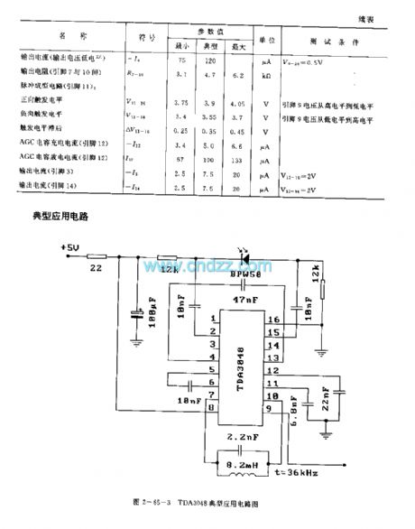

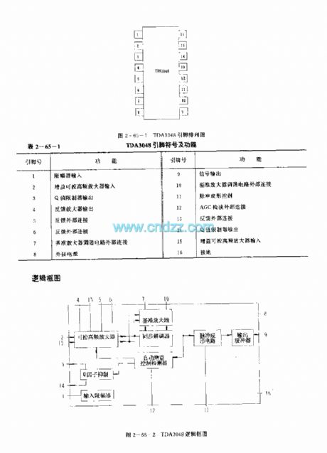
The TDA3048 is designed as one kind of low power consumption infrared remote control receiving circuit that can be used in the TV application. The internal circuit is composed of the controllable high-frequency amplifier (the control range is 66dB), the synchronous demodulator, the reference amplifier, the automatic gain control detector, the input voltage limiter circuit, the pulse shaping circuit and the output buffer. The difference of the TDA3047 and TDA3048 is the polarity of the output signal. This device is in the 16-pin dual-row DIP plastic package.
(View)
View full Circuit Diagram | Comments | Reading(1001)
Super-regenerative receiver module CS902 can be used with the emission component CS901
Published:2011/7/18 21:49:00 Author:TaoXi | Keyword: Super-regenerative receiveremission component
The antenna receives the emission signal and makes the signal get through the filter that is composed of the L1 and C1, so the 315Hz signal gets the maximum gain. The receiving signal is amplified by the high frequency amplifier which is composed of VT1, so the receiving signal has the larger signal amplitude. The signal of VT1 gets into the super-regenerative detector circuit which is composed of the VT2, L0, C7 and C7, C10.etc to be detected. The output detection signal of the VT2 is amplified by the two-stage amplifier which is composed of the LM358 dual op-amp circuit, then it is sent out to the digital decoder from the output port.
(View)
View full Circuit Diagram | Comments | Reading(1107)
The mini wireless call systems BA1401/TDA7010T
Published:2011/7/18 21:47:00 Author:TaoXi | Keyword: mini, wireless call system
Transmitter (View)
View full Circuit Diagram | Comments | Reading(838)
The Digital code control switch digital woven decoder MC145026/MC145027 and the mini radio transceiver module M303S/M303R
Published:2011/7/18 21:46:00 Author:TaoXi | Keyword: Digital code, control switch, digital woven decoder, mini radio transceiver
The digital code control switch digital woven decoder MC145026/MC145027 and the mini radio transceiver module M303S/M303R is as shown. When you press the transmitter button SA, the circuit gets the electricity to start working, the serial coding signal is output from the pin-15 of MC145026 and then it is sent out by the M303S launch module. Receiving module M303R of the receiving circuit receives the serial coding signal, then modulates the encoded signal and sends it to the MC145027 decoder, when the decoder's address and coding are the same, MC145027's decoding effective instruction end outputs the high-level pulse signal, the transistor VT conductsand drives the relay to close, also it completes the switch control function.
(View)
View full Circuit Diagram | Comments | Reading(808)
The computer motherboard circuit diagram 810 3_13
Published:2011/7/20 20:32:00 Author:Ecco | Keyword: computer motherboard
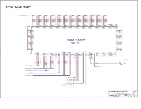
View full Circuit Diagram | Comments | Reading(769)
Optical communication receiving circuit
Published:2011/5/11 8:44:00 Author:Nicole | Keyword: optical communication receiving
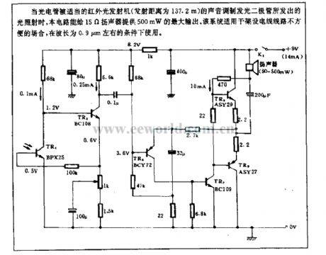
When the phototube is shined by the light which is produced by proper sound modulation LED of IR light transmitter(the transmitting distance is 137.2m), this circuit can provide 15Ω loudspeaker with 500mW maximum output. This system is suitable for the occasion where's difficult to install the electric wire, and it can be used when the wave length is about 0.9μm. (View)
View full Circuit Diagram | Comments | Reading(1355)
Optical pulse receiving circuit
Published:2011/5/11 8:41:00 Author:Nicole | Keyword: optical pulse
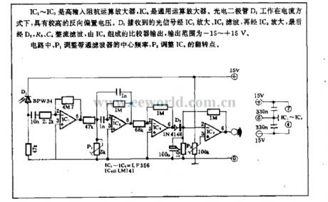
IC1~IC3 are high input resistance operational amplifier, IC4 is common operational amplifier. Photodiode D1 works with current, it has higher reverse bias voltage. The light signal received by D1 is amplified by IC1, filtered by IC2, amplified by IC3 again, then rectifier filtered by D2, R8, C4, outputed by comparator composed of IC4, its output range is -15~+15V.
In figure, P1 adjusts the middle frequency of bandpass filter, P2 adjusts the flipping point of IC4. (View)
View full Circuit Diagram | Comments | Reading(1463)
MC14469 general addressable asynchronous launch or receiving circuit
Published:2011/7/18 6:50:00 Author:Christina | Keyword: general, addressable, asynchronous, launch, receiving circuit
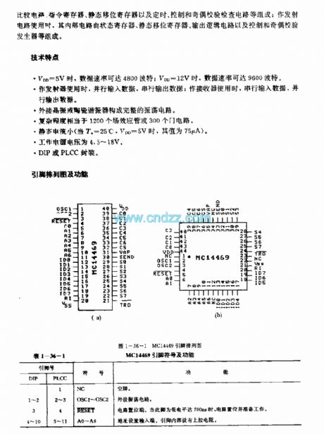
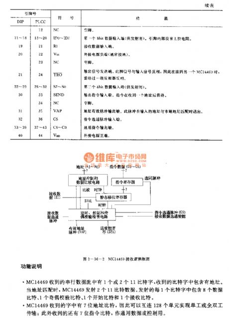
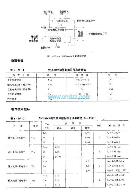
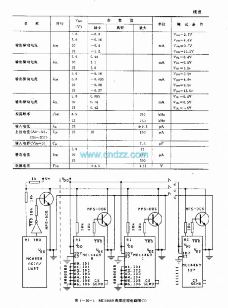
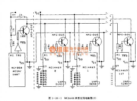
The MC14469 is designed as one kind of general addressable asynchronous launch or receiving circuit that can be used in the remote control analog to digital conversion, the remote control microprocessor and control the digital converter which is connected with the host or the microprocessor. When it is used as the receiving circuit, the internal circuit is composed of the address control and data comparison circuit, the instruction register, the static shift register and the timing, control and parity checking circuit; when it is used as the transmitter circuit, the internal circuit is composed of the status register, the static shift register, the output logic circuit and the control and parity generator.
(View)
View full Circuit Diagram | Comments | Reading(1106)
SB-50ALTX receiver
Published:2011/7/17 5:38:00 Author:Christina | Keyword: receiver
SB-50ALTX receiver (View)
View full Circuit Diagram | Comments | Reading(715)
MC3367 (communication equipment) FM receiver circuit
Published:2011/7/15 22:11:00 Author:Christina | Keyword: communication equipment, FM, receiver
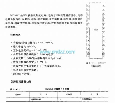
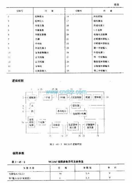
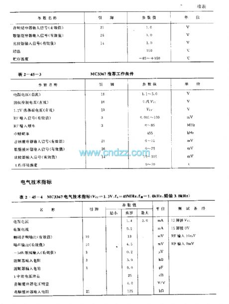
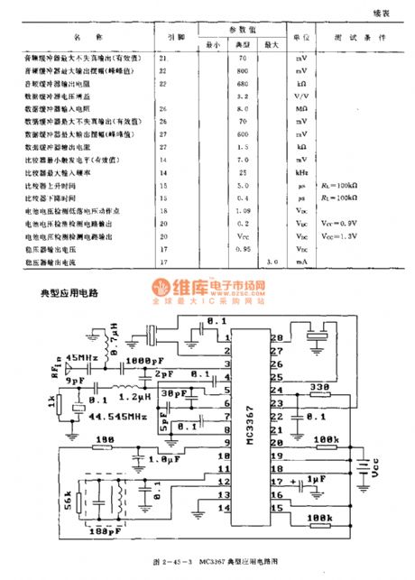
The MC3367 is designed as one kind of FM receiver circuit that can be used in the communication equipments such as the BB machine. The internal circuit is composed of the oscillator, the mixer, the intermediate frequency amplifier, the intermediate frequency amplitude limiting device, the quadrature discriminator, the voltage stabilizer, the battery step-down detector, the receiver controller, the audio buffer amplifier, the data buffer amplifier and the comparator circuits.
Features
Low power consumption (the static power consumption is 1.5-5.0mW);The input bandwidth is 75 MHz;The operating voltage is low, Vcc=1.1-3.0V;The internal voltage stabilizer supplies the 3.0mA current;High sensitivity;The bandwidth of the data comparison is higher than 25kHz;The receiving control makes the integrated circuit in the operating or waiting state;Low battery voltage detection circuit;28-pin Flat package.
(View)
View full Circuit Diagram | Comments | Reading(1261)
COP880C--the communication single chip microcomputer integrated circuit
Published:2011/7/12 22:16:00 Author:Borg | Keyword: communication single chip, microcomputer
COP880C is the communication single chip microcomputer integrated circuit, which is often used in the multi-channel wireless phones.1.function featuresCOP880C contains pulse/dual audio with dialing circuit, wireless emitting and receiveing signal process control circuit, channel manual or auto switching circuit, fast auto receiving lines selecting circuit, keypad switch signal encoding circuit, power supply detection circuit, charge detection circuit, mute control circuit, ringing detection circuit, audio channel circuit (for communication) and other function circuits.
(View)
View full Circuit Diagram | Comments | Reading(780)
Transceiver module of the telephone wireless ringing circuit composed of RCMlA/RCMlB
Published:2011/7/8 5:57:00 Author:TaoXi | Keyword: Transceiver module, telephone, wireless ringing circuit
The transmitter directly connects to the telephone line in parallel mode, and this device does not need the external power supply. The isolation effect of the capacitance C1 makes the launcherdo not affect the normal work of the telephone.
(View)
View full Circuit Diagram | Comments | Reading(744)
Transceiver module composed of the remote control voice doorbell RCMlA/RCMlB
Published:2011/7/8 5:59:00 Author:TaoXi | Keyword: Transceiver module, remote control, voice doorbell
The remote control doorbell saves the wiring between the button and the doorbell, the installation position of the doorbell is very flexible and it is convenient. The voice integrated circuit can use the KD15 series of soft packaging integrated circuit. After the circuit is installed, you can use it immediately. when you are using it, you should make the receiver away from the big metal objects to avoid the influencing of the remote sensitivity.
(View)
View full Circuit Diagram | Comments | Reading(842)
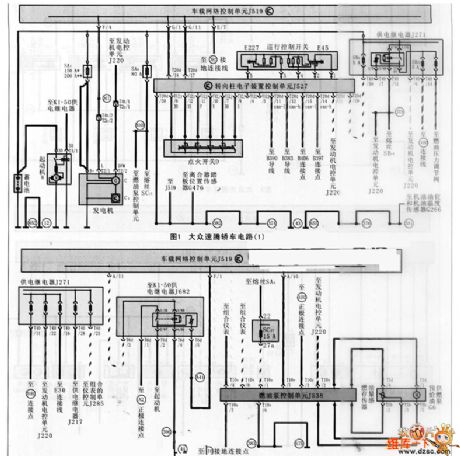
Volkswagen Jetta sedan car circuit
Published:2011/7/6 9:08:00 Author:John | Keyword: car
View full Circuit Diagram | Comments | Reading(885)
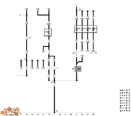
FAW-Volkswagen Jetta 2005 model car maintenance information circuit
Published:2011/7/6 9:07:00 Author:John | Keyword: car, maintenance information, car
View full Circuit Diagram | Comments | Reading(894)
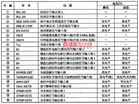
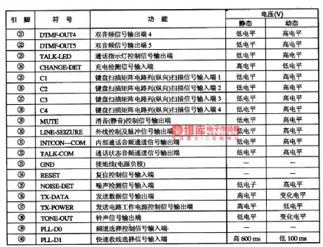
The Communication Single Door PC Intergrated Circuit of C807-1354
Published:2011/6/14 23:23:00 Author:Borg | Keyword: Intergrated Circuit, Communication, Single Door
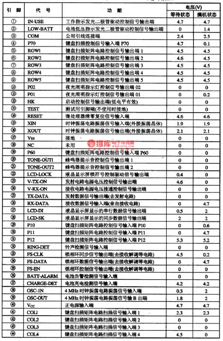
C807一1354 is an PC intergrated circuit of communication single door which is used in wirless phones as the bus master of cell phones.
1.function features
C807一1354 intergrated circuits contain control circuits of wireless delivering/receiving,LCD drive, lighting lamps, key switch encoding/decoding, clock shocking, in it, phase-locked loop signal handling, buzzer drive, code generating and conditioning, low voltage test,charging and othe functions.
2.pin functions and relevent data
C807—1354 intergrated circuits areencapsulated with 44-lead,whose pin functions and data are listed in Table 1.
Table 1 pin functions and data of C807-1354 (View)
View full Circuit Diagram | Comments | Reading(746)
| Pages:24/32 At 20212223242526272829303132 |
Circuit Categories
power supply circuit
Amplifier Circuit
Basic Circuit
LED and Light Circuit
Sensor Circuit
Signal Processing
Electrical Equipment Circuit
Control Circuit
Remote Control Circuit
A/D-D/A Converter Circuit
Audio Circuit
Measuring and Test Circuit
Communication Circuit
Computer-Related Circuit
555 Circuit
Automotive Circuit
Repairing Circuit