
Communication Circuit
Index 31
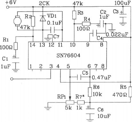
Hitachi NP8C Movement Power Supplier Circuit
Published:2011/4/24 21:12:00 Author:Christina | Keyword: Movement Power Supplier
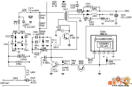
The Hitachi NP8C Movement Power Supplier Circuit is as shown:
(View)
View full Circuit Diagram | Comments | Reading(682)
UM3758-108A/AM New single-chip encoding and decoding circuit diagram
Published:2011/4/24 4:50:00 Author:Rebekka | Keyword: single-chip , encoding and decoding
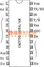
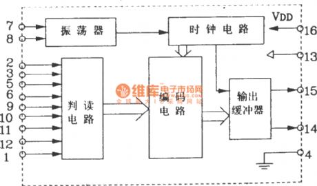
UM3758-108A/AM shape pin map
UM3758-108A/AM encoding and decoding integrated circuit has the function of encoding sending and decoding receiving. The device itself has 10-bit three-state address inputs and 8-bit latch functions with a variety of ways to achieve long-distance remote control. It has the unique dual-duplex transceiver remote control and body functions. At present, this device is widely used in automotive, defense of the motherland, safe, mobile phones and military communications and other aspects of remote control, alarm, and password control circuits.
Electrical parameters UM3758-108A/AM electrical parameters are identical. The main electrical parameters are: Working voltage range 3 ~ 12V, typical application voltage of 6V or 9V; Receiving input high minimum 4V, low maximum value of 2V; Other input level VIH = (VDD-0.5V ) ~ VDD, VIL = 0.5V; Output level VoH = (VDD-0.5V) ~ VDD, VOL = 0 ~ 1V; Data output current is ± 10mA (level is VDD / 2 时); TX / Rx-ended output current up-40mA or +20 mA; Chip operating clock oscillation frequency fosc = 160kHz.
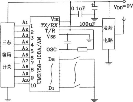
Remote code transmission circuit composed of UM3758-108A/AM
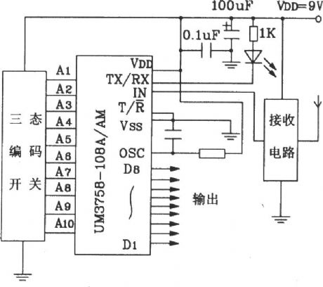
Remote decode transmission circuit composed of UM3758-108A/AM
(View)
View full Circuit Diagram | Comments | Reading(2072)
TA8859 pincushion correction circuit diagram
Published:2011/4/24 3:26:00 Author:Rebekka | Keyword: pincushion correction circuit
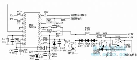
Field excitation pulse input
N402 (TA8859) 2 foot parabolic wave output voltage is amplified by the V401 ~ V403, and outputs the parabolic wave by V403 collector. It will be sent to the line deflection coil and change the flow through the line deflection coil current. That is, completion of the East / West pincushion correction. The east / west pincushion correction is sent to bus adjustment mode.
Pin 1: 3.7V-- high stability detection input Pin 2: 1.1V-- something the school pillows parabolic wave output Pin 3: 12.0V-- +12 V voltage input Pin 4: 5.5V-- something the school pillows feedback input side Pin 5: 0V - to Pin 6: 4.2V-- the input field scanning FeedbackPin 7: 0V Pin 8: 2.1V-- Field sawtooth voltage output Pin 9: 4.8V-- Bus cable connector Pin 10: 4.8V-- Bus clock line Pin 11 connector: 0V- - empty pin Pin 12: 0V - to Pin 13: 4.4V-- field excitation pulse signal input Pin 14: 3.8V-- external pulse shaping filter side Pin 15: 6.0V-- field scanning ramp voltage to form side Pin 16: 3.0V-- end automatic gain control filter
(View)
View full Circuit Diagram | Comments | Reading(1745)
Composed of KD704 and KD705 RF remote control transmitter and receiver circuit diagram
Published:2011/4/21 3:54:00 Author:Rebekka | Keyword: remote control , transmitter and receiver
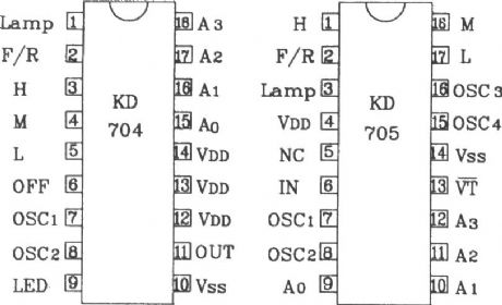
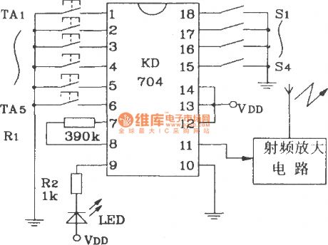
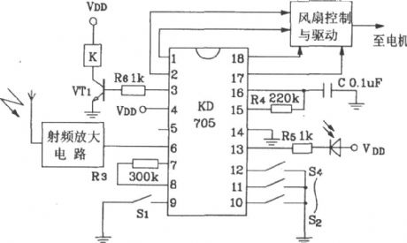
KD704/KD705 is a pair of RF remote control transmitter / receiver CMOS LSI specifically designed for electric fans and lights.
KD704/705 shape pin map.
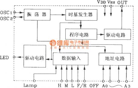
KD704 internal block diagram.
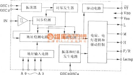
KD705 internal block diagram.
RF remote control receiver circuit composed of KD705.
(View)
View full Circuit Diagram | Comments | Reading(2982)
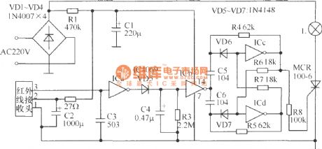
Appliances infrared remote control receiver circuit diagram
Published:2011/4/20 22:31:00 Author:Rebekka | Keyword: Appliances , infrared remote control, receiver
View full Circuit Diagram | Comments | Reading(1284)
Composed of FDD400/JDD400 multiple alarm system circuit diagram
Published:2011/4/21 2:11:00 Author:Rebekka | Keyword: multiple alarm system

The multiple wireless alarm system is composed of FDD400/JDD400 and integrated digital decoding circuit VD5026/VD5027 (View)
View full Circuit Diagram | Comments | Reading(1067)
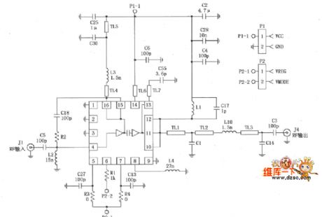
Composed of LM1871 and 1872 typical remote control transmitter and receiver circuit diagram
Published:2011/4/21 2:00:00 Author:Rebekka | Keyword: remote control , transmitter and receiver

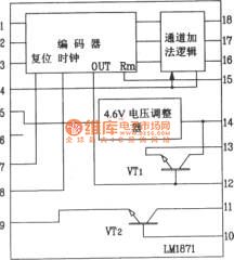
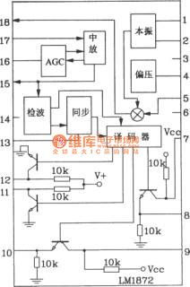
LM1871/1872 a large-scale electric guitar without remote control transmitter / receiver ASIC.
LM1871/1872 shape pin function diagram.
LM1871 internal schematic.
LM1872 internal block diagram.
LMl871/1872 radio-controlled special chip operating voltage range is 3 ~ 9V; Transmitter chip LMl871 frequency up to 80MHz, frequencies up to 80MHz. It is optional; It contains the oscillator, the transmitter and encoder; Channels are programmable, and the RF output power is adjustable. General remote control distance up to tens of meters. If increase the supply voltage appropriately, and add one or two high-amp circuit, the remote control distance can be increased to l~2km.
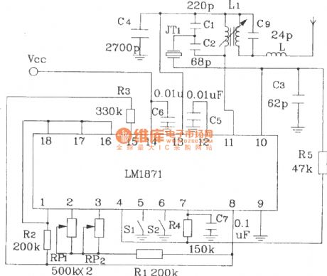
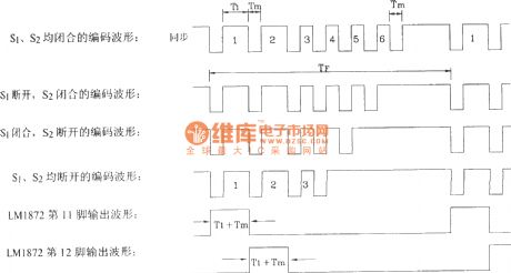
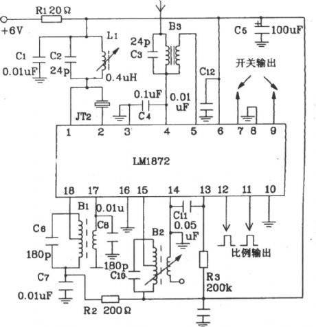
Here is a typical remote control transmitter / receiver circuit composed of LM1871/1872:
(View)
View full Circuit Diagram | Comments | Reading(2964)
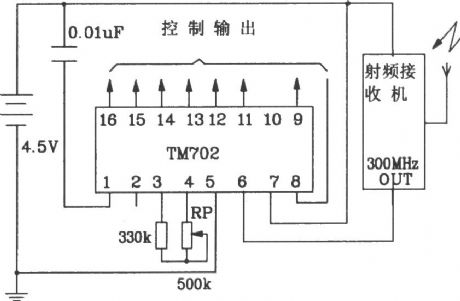
Composed of TM701 and TM702 RF remote control transmitter and receiver circuit diagram
Published:2011/4/21 4:14:00 Author:Rebekka | Keyword: RF remote control, transmitter and receiver

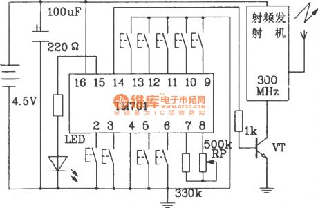
TM701/702 dedicated remote control transmitter / receiver integrated circuits and TM703/702 infrared remote control transmitter / receiver integrated circuits are dedicated remote control devices of the same class.
TM701 shape pin map.
TM701 internal block diagram.
RF remote control transmitter circuit composed of TM701.
Radio remote control receiver circuit composed of TM702.
(View)
View full Circuit Diagram | Comments | Reading(3631)
Composed of MC3372 and MC341196D 45MHz band radio receiver circuit diagram
Published:2011/4/21 4:20:00 Author:Rebekka | Keyword: band radio receiver

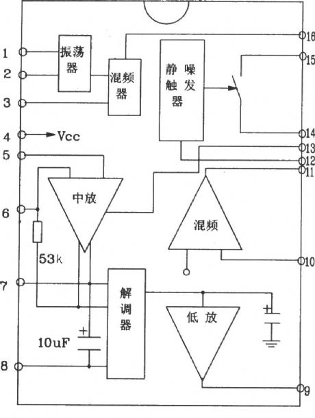
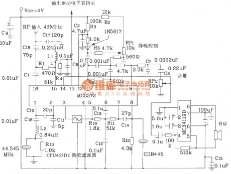
MC3373-specific integrated circuit radio receiver is low-power narrowband FM receiving device of Motorola. It operates up to 100MHz.
MC3372 pin function diagram form.
MC3372 internal block diagram.
45MHz band radio receiver circuit composed of MC3372 and MC341196D.
(View)
View full Circuit Diagram | Comments | Reading(3031)
1/10/100kb light receiving circuit
Published:2011/4/20 1:16:00 Author:muriel | Keyword: 1/10/100kb, light receiving circuit
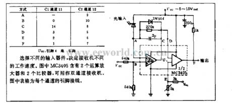
The working speed of receiver is decided by the input device. The figure MC3405 contains 2 amplifiers and 2 comparators,they can be used as a dual channel receiver. The form in the Diagram is pins wiring for every channel.
(View)
View full Circuit Diagram | Comments | Reading(601)
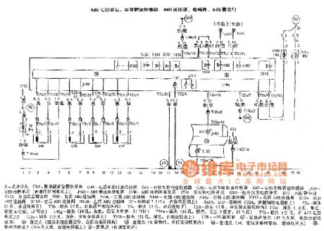
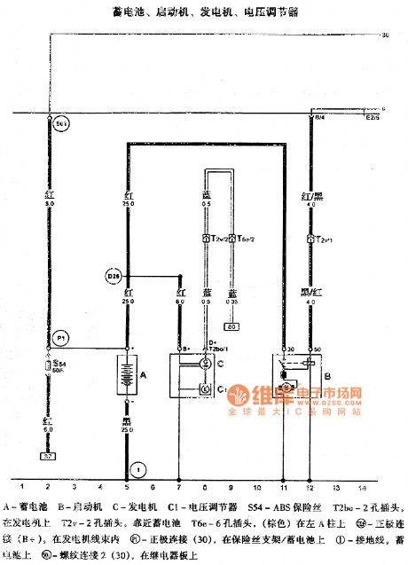
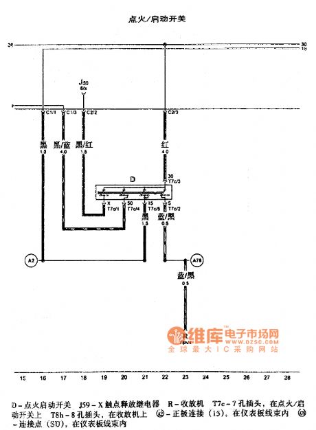
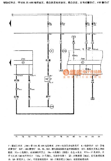
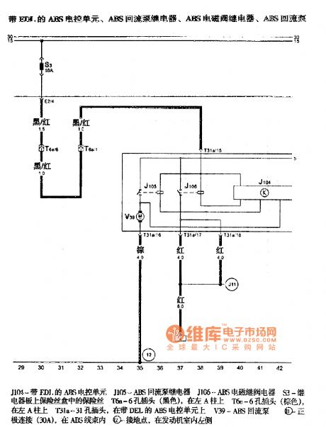
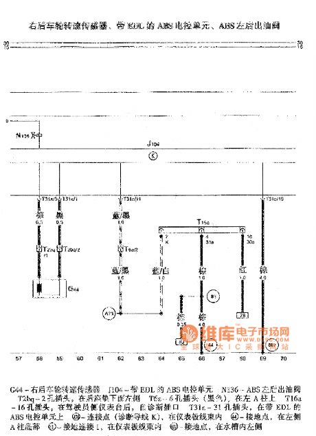
Passat ABS circuit
Published:2011/4/20 2:57:00 Author:Jessie | Keyword: ABS
View full Circuit Diagram | Comments | Reading(1668)
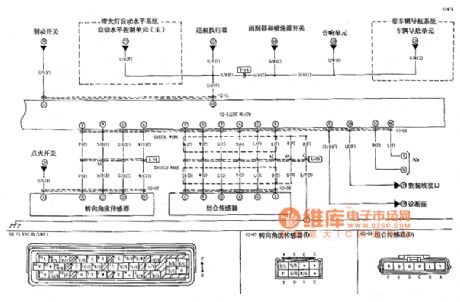
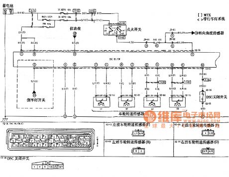
M6 car DSC system circuit
Published:2011/4/20 2:38:00 Author:Jessie | Keyword: DSC system
View full Circuit Diagram | Comments | Reading(840)
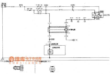
M6 car AC compressor control circuit
Published:2011/4/20 2:35:00 Author:Jessie | Keyword: AC compressor control
View full Circuit Diagram | Comments | Reading(1160)
America TDMA application circuit composed of RF2162
Published:2011/4/2 4:22:00 Author:may | Keyword: America TDMA
RF2162 constitutive America TDMA application circuit is show in the following picture:
(View)
View full Circuit Diagram | Comments | Reading(1349)
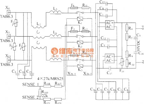
DMAl2 Formation picture
Published:2011/4/14 1:31:00 Author:muriel | Keyword: Formation picture
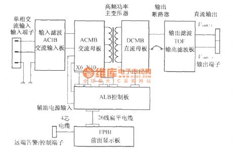
DMA12 intelligent switch Rectifier Module are composed of the ACIB, ACMB, DCMB, TOF, ALB, FPBI.There are a total of six printed board and input and output plugs, circuit breakers, inductors and transformers and other components, as shown. (View)
View full Circuit Diagram | Comments | Reading(734)
Gaoer ABS circuit
Published:2011/4/14 22:24:00 Author:Jessie | Keyword: ABS

View full Circuit Diagram | Comments | Reading(764)
20kbits optical receiving circuit
Published:2011/4/1 21:56:00 Author:may | Keyword: 20kbits, optical receiving
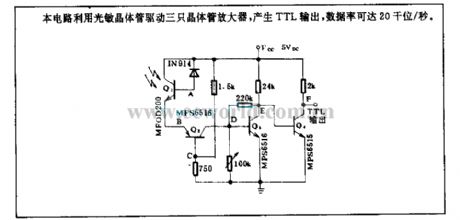
This circuit adopts optical transistor to drive three crystal amplifiers. It can generate TTL output. Its data rate can reach 20kbits/s.
(View)
View full Circuit Diagram | Comments | Reading(647)
DMA lossless absorption buffer circuit
Published:2011/3/21 0:52:00 Author:muriel | Keyword: DMA , lossless, absorption, buffer circuit
View full Circuit Diagram | Comments | Reading(663)
DMA input circuit
Published:2011/3/21 0:51:00 Author:muriel | Keyword: DMA, input circuit
View full Circuit Diagram | Comments | Reading(845)
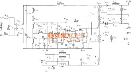
DMA auxiliary power supply circuit
Published:2011/3/21 1:29:00 Author:muriel | Keyword: UC3854, DMA , auxiliary power supply
View full Circuit Diagram | Comments | Reading(1281)
| Pages:31/32 At 20212223242526272829303132 |
Circuit Categories
power supply circuit
Amplifier Circuit
Basic Circuit
LED and Light Circuit
Sensor Circuit
Signal Processing
Electrical Equipment Circuit
Control Circuit
Remote Control Circuit
A/D-D/A Converter Circuit
Audio Circuit
Measuring and Test Circuit
Communication Circuit
Computer-Related Circuit
555 Circuit
Automotive Circuit
Repairing Circuit