
Index 164
LONG_DELAY_TIMER_USING_PUT
Published:2009/6/25 21:09:00 Author:May
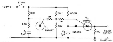
Circuit NotesThe PUT is used as both a timing element and sampling oscillator. A low leakage film capacitor is required for C2 due to the low current supplied to it. (View)
View full Circuit Diagram | Comments | Reading(658)
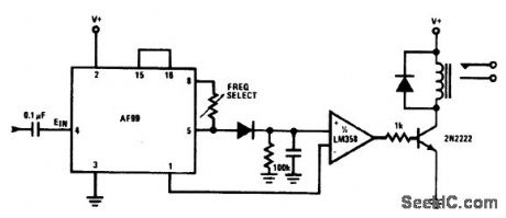
PREPROGRAMMED_SINGLE_CHIP_MICROCONTROLLER_FOR_MUSICAL_ORGAN
Published:2009/6/25 20:59:00 Author:May
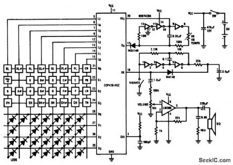
Twenty-five musical keys and 25 LEDs are provided to denote F to F with half notes in between. Memory can store a played tune. There are ten preprogrammed tunes (each has an average of 55 notes) masked in the chip. Any tune can be recalled by depressing the Tune Button followed by the corresponding Sharp Key. In team mode, the player can learn the ten preprogrammed tunes. (View)
View full Circuit Diagram | Comments | Reading(721)
DOOR_CHIMES_DELAY
Published:2009/6/25 21:06:00 Author:Jessie
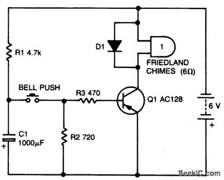
Circuit NotesWith values shown, this simple circuit will permit one operation every 10 seconds or so.Capacitor C1 charges through RI when the button is released. Making RI larger crease the delay. (View)
View full Circuit Diagram | Comments | Reading(1291)
TONE_DECODER_WITH_RELAY_OUTPUT
Published:2009/6/25 20:48:00 Author:May
View full Circuit Diagram | Comments | Reading(0)
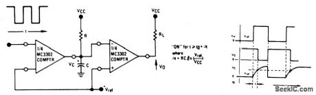
TIME_DELAY_GENERATOR
Published:2009/6/25 21:03:00 Author:Jessie
View full Circuit Diagram | Comments | Reading(0)
LONG_TIME_DELAY
Published:2009/6/25 21:02:00 Author:Jessie
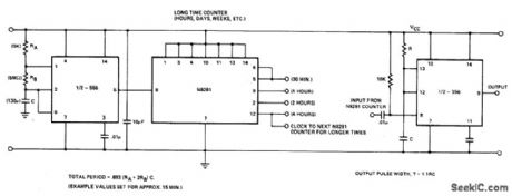
Circuit NotesIn the 556 timer, the timing is a function of the charging rate of the external capacitor. For long time delays, expensive capacitors with extremely low leakage are required. The prac-ticality of the components involved limits the time between pulses to something in the neighborhood of 10 minutes. To achieve longer time periods, both halves of a dual timer may be connected in tandem with a Divide-by ' net-work in between the first timer section oper-ates in an oscillatory mode with a period of 1/fo. This signal is then applied to a Divide-by-N network to give an output with the period of N/fo. This can then be used to trigger the second half of the 556. The total time delay is now a function of N and fo. (View)
View full Circuit Diagram | Comments | Reading(1673)
DIGITAL_WEIGHT_SCALE
Published:2009/6/25 20:38:00 Author:May
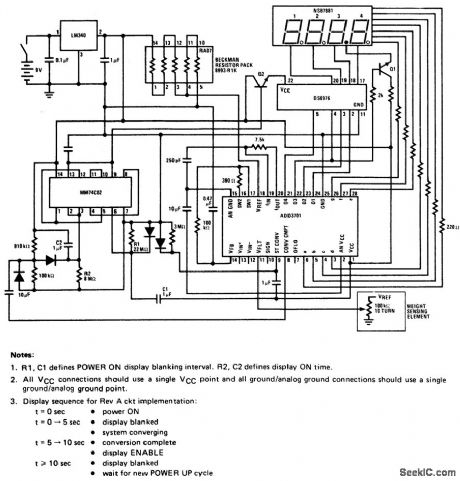
This circuit employs a potentiometer as the weight sensmg element.An object placed upon the scale displaces the potentiometer wiper,an amount proportional to its weight.Conversion of the wiper voltage to digital infomation is performed,decoded,and interfaced to the numerlc display. (View)
View full Circuit Diagram | Comments | Reading(5284)
TONE_DECODER_WITH_RELAY_OUTPUT
Published:2009/6/25 20:48:00 Author:Jessie
View full Circuit Diagram | Comments | Reading(1722)
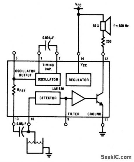
LOW_LEVEL_WARNING_WITH_AUDIO_OUTPUT
Published:2009/6/25 2:53:00 Author:May
View full Circuit Diagram | Comments | Reading(977)
FLOOD_ALARM
Published:2009/6/25 2:51:00 Author:May
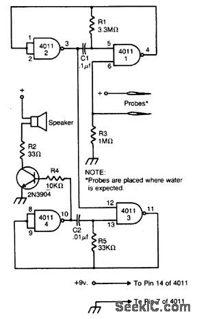
The alarm is built around two audio oscillators, each using two NAND gates. The detection oscillator is gated on by a pair of remote probes. One of the probes is connected to the battery supply, the other to the input of one of the gates. When water flows between the probes, the detection oscillator is gated on.The alarm oscillator is gated on by the output of the detection oscillator. The values given produce an audio tone of about 3000 Hz. The detection oscillator gates this audio tone at a rate of about 3 Hz. The result is a unique pulsating note. Use any 8 ohm speaker to sound the alarm. The 2N3904 can be replaced by any similar NPN transistor. The circuit will work from any six to 12-volt supply. (View)
View full Circuit Diagram | Comments | Reading(3023)
WATER_LEVEL_SENSING_CONTROL_CIRCUIT
Published:2009/6/25 2:50:00 Author:May


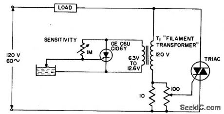
The circuit applies power to the load until the water conducts through the probe, and bypasses gate current from the low current SCR. This gives an isolated low voltage probe to satisfy safety requirements. (View)
View full Circuit Diagram | Comments | Reading(765)
WATER_LEVEL_ALARM
Published:2009/6/25 2:49:00 Author:May
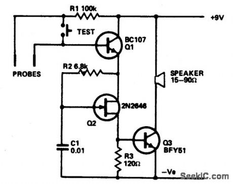
The circuit draws so little current that theshelf-line of the battery is the limiting factor.The only current drawn is the leakage of the transistor. The circuit is shown in the form of awater level alarm but by using different forms of probe can act as a rain alarm or shorting ween the probes will trigger it. Q1 acts as a switch which applies current to the unijunction relaxation oscillator Q2. Alarm signal frequency is controlled by values and ratios of C1/R2. Pulses switch Q3 on and off, applying a signal to the speaker. Almost any NPN silicon transistor can be used for Q1 and Q3 and almost any unijunction for Q2. (View)
View full Circuit Diagram | Comments | Reading(120)
LIQUID_LEVEL_CONTROL
Published:2009/6/25 2:47:00 Author:May
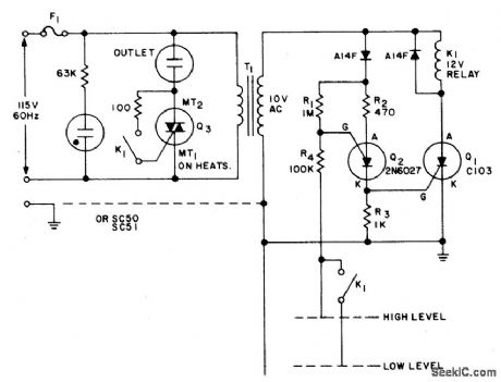
Use this circuit to keep the fluid level of a liquid between two fixed points. Two modes, for filling or emptying are possible by simple reversing the contact connections of K1. The loads can be either electric motors or solenoid operated valves, operating from ac power.Liquid level detection is accomplished by two metal probes, one measuring the high level and the other the low level. An inversion of the logic (keeping the container filled) can be accomplished by replacing the normally open contact on the gate of Q3 with a normally closed contact. (View)
View full Circuit Diagram | Comments | Reading(0)
FLUID_LEVEL_CONTROLLER
Published:2009/6/25 2:44:00 Author:May
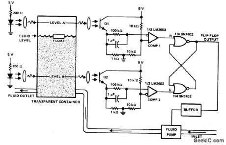
This circuit can be used to maintain fluid between two levels. Variations on this control circuit can be made to keep something that moves within certain boundary conditions. (View)
View full Circuit Diagram | Comments | Reading(689)
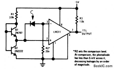
PRECISION_PHOTODIODE_COMPARATOR
Published:2009/6/25 2:28:00 Author:Jessie
View full Circuit Diagram | Comments | Reading(0)
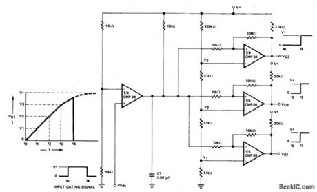
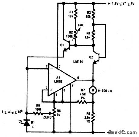
3LIGHT_METER
Published:2009/6/25 2:27:00 Author:Jessie
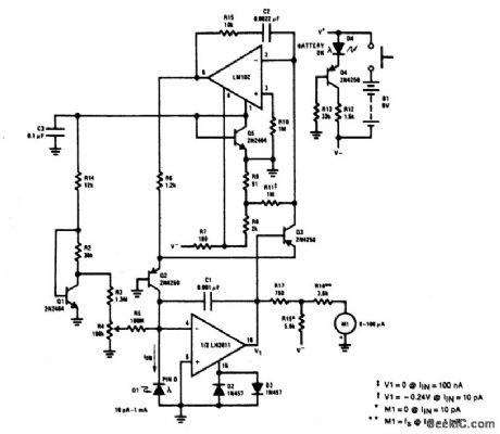
This light meter has an eight-decade range. Bias current compensation can give input current resolution of better than ±2 pA over 15 ℃ to 55℃. (View)
View full Circuit Diagram | Comments | Reading(1257)
2LIGHT_METER
Published:2009/6/25 2:25:00 Author:Jessie
View full Circuit Diagram | Comments | Reading(1170)
SHIFT_REGISTER
Published:2009/6/25 2:17:00 Author:Jessie
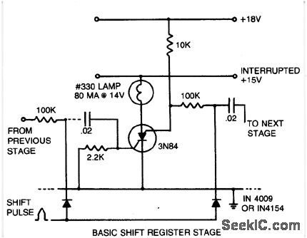
The shift pulse amplitude is less than 15 volts. If a stage is off,the shift pulse will not becoupled to the next stage,If it is on,the diode will conduct and trigger the next stage.Just prior to the shift pulse the anode supply is interrupted to turn off all stages.The stored capacitor charge determines which stages will be triggered, (View)
View full Circuit Diagram | Comments | Reading(0)
COMPLEMENTARY_AC_POWER_SWITCHING
Published:2009/6/25 2:11:00 Author:May
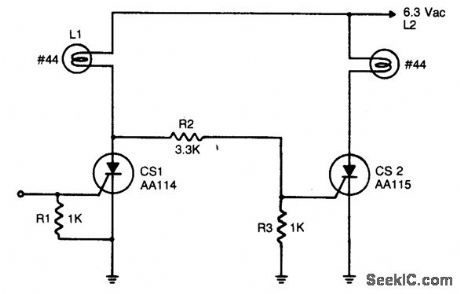
An input signal of less than 1 mA and 1 V is required to switch on CS1. As long as this input signal is maintained, CS1 will conduct during each positive half cycle of anode voltage, thereby energizing load L1 with half-wave rectified dc. L2 remains de-energized, since the anode of CS1 will not go more positive than 1.5 volts, and voltage divider R2 - R3 cannot provide enough voltage to trigger CS2. Upon removal of the input signal, CS1 will drop out.L1 will be de-energized, except for a small amount of ac current through R2 and R3. CS2will be triggered on at the beginning of each positive half-cycle, when CS1 anode voltage reaches 2 to 3 volts. CS2 will conduct for nearly the entire positive half-cycle energizing L2. It should be noted that the 6.3 volt lamps used will operate at 1/3 the rated brilliance because of the controlled switch half-wave rectifying action and will extend the operating lamp life by several orders of magnitude. Should full brilliance be desired, the anode supply voltage level should be raised to 9 volts ac. (View)
View full Circuit Diagram | Comments | Reading(0)
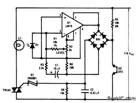
LIGHT_LEVEL_CONTROLLER
Published:2009/6/25 2:16:00 Author:Jessie
View full Circuit Diagram | Comments | Reading(617)
| Pages:164/312 At 20161162163164165166167168169170171172173174175176177178179180Under 20 |
Circuit Categories
power supply circuit
Amplifier Circuit
Basic Circuit
LED and Light Circuit
Sensor Circuit
Signal Processing
Electrical Equipment Circuit
Control Circuit
Remote Control Circuit
A/D-D/A Converter Circuit
Audio Circuit
Measuring and Test Circuit
Communication Circuit
Computer-Related Circuit
555 Circuit
Automotive Circuit
Repairing Circuit