
Index 178
PROGRAMMABLE_LIGHT_ACTIVATED_RELAY
Published:2009/6/22 22:47:00 Author:Jessie
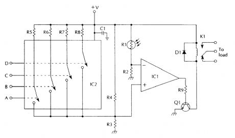
Digital inputs A, B, C, D select different light levels by varying the value of bridge circuit resis-tance R4.IC1 741 op ampIC2 CD4066 quad bilateral switchQ1 NPN transistor (2N2222, 2N3904, or similar) D1 diode (1N4002, or similar)C1 0.1-μF capacitorR1 photoresistorR2, R3 390-kΩ, 1/4-W 5% resistorR4, R5 1-MΩ, 1/4-W 5% resistorR6 820-kΩ, 1/4-W 5% resistorR7 470-kΩ, 1/4-W 5% resistorR8 270-kΩ, 1/4-W 5% resistorR9 100-kΩ, 1/4-W 5% resistorK1 relay to suit load (View)
View full Circuit Diagram | Comments | Reading(1937)
LIGHT_CONTROLLED_MONOSTABLE
Published:2009/6/22 22:44:00 Author:May
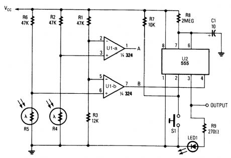
The light-controlled monostable was produced by combining a 555 monostable multivibrator with a pair of light-controlled comparators. The circuit can be used to enable the operation of the load device, depending on the time of day. During the daylight hours, the timer U2, is disabled, and so produces no output. However, during the nighttime hours, U2 is enabled by the output of UI-b so that pressing S1 initiates a timing cycle, which activates LED1 for a time determined by R8 and C1. (View)
View full Circuit Diagram | Comments | Reading(1120)
OPTICAL_FRINGE_COUNTER
Published:2009/6/22 22:39:00 Author:May
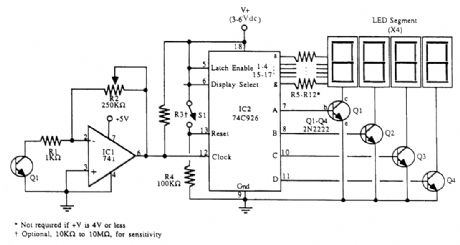
For work with interferometer and optical experiments, this fringe counter can be useful. Photo transistor Q1 provides light and dark sensing. As the sensor is moved across the fringe pattern alternate light and dark areas translate to an electrical waveform. This is amplified by IC1 and counted by IC2. A Schmitt trigger circuit can be added, if desired. (View)
View full Circuit Diagram | Comments | Reading(3273)
50_MHz_FREQUENCY_COUNTER
Published:2009/6/22 22:34:00 Author:May
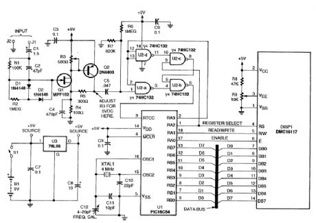
This inexpensive frequency counter uses a microcontroller as the counter. The rrticrocontroller feeds an LCD display module that accepts standard ASCII code. The frequency is displayed as Hz, kHz, or MHz and the counter is autoranging. (View)
View full Circuit Diagram | Comments | Reading(2796)
Fan speed controller diagram 1
Published:2011/6/27 20:25:00 Author:Nora | Keyword: Fan , speed , controller
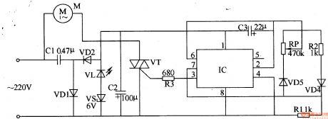
Step-down power supply circuit consists of the capacitor Cl, rectifier diodes VDl, VD2, filter capacitor C2, the power indicator light-emitting diode composed of VL and VS regulator diode.Controlled oscillator consists of a time-base integrated circuit IC, resistors RI, R2, capacitors C3, potentiometer RP and diode VD3, VD4 formed.Control implementation of the circuit consists of the fan motor M, thyristor VT, resistor R3 and the first 3 feet inside the IC circuit.AC 220V voltage buck by Cl, VDl and VD2 rectified, VL and VS filtered and C2 regulated, the IC provides about 8V DC voltage.Controlled oscillator work, a 3-pin output from the IC cycle 105, the duty cycle adjustable oscillating pulse signal, the use of this pulse signal to control the conduction status of thyristor VT.Adjust the resistance of RP, you can change the pulse duty cycle (adjustment range of 1% -99%), control the level of the fan motor M speed, resulting in simulated natural wind (gusts period of 10s).Change the capacitance of C3, can change the oscillator weeks moon, thus changing the simulation of natural wind cycle. (View)
View full Circuit Diagram | Comments | Reading(2652)
Infrared remote control dimmer, speed controller diagram 1
Published:2011/6/26 20:36:00 Author:Nora | Keyword: Infrared, dimmer, controller
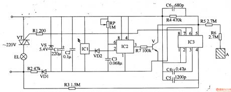
AC 220V voltage filtered by R2-limiting step, VDl rectifier, VS regulator and Cl, C2. It provide DC voltage about 5V for ICl-IC3 (Vcc).In pressing the remote control button, the remote control infrared remote control pulse(the time is less than 0.45 when press the remote control button , the remote control application output pulses 1-3; if the remote control button press time over .45 , the output of the remote control more than 3 Burst). 1C1 will receive the infrared pulse train amplification, demodulation, and plastic surgery and other treatment, output a low pulse, the VD2 turn, C3 quickly discharges. When the voltage across C3 is lower than Vcc / 3 时, IC2's output of 3 feet high, so that V conduction. When through a pulse train, VD2 end, +5 V voltage charging of C3 by the RP, the IC2 pin 2, 6-pin voltage rise, when the voltage is increased to 2Vcc / 3 时, lC2 flip-circuit, 3-pin change low, V cut-off. If the new moon in the C3 charge between ICl and output a low pulse, C3 will discharge again, then keep the output of IC2 3 feet high. (View)
View full Circuit Diagram | Comments | Reading(2603)
Thermostat, governor diagram 2
Published:2011/6/26 21:02:00 Author:Nora | Keyword: Thermostat, governor , diagram
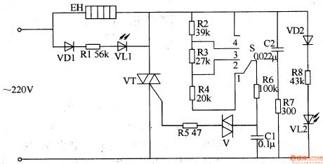
When the power selector adjust the switch S, it can change the capacitor charge and discharge rate of Cl, thus change the thyristor conduction angle. Cl through V to the voltage across the trigger and make it turn-VT, by changing the conduction angle of VT to change the electric heater EH (load) both ends of the AC voltage level. VLl and VL2 for the working status indicator LEDs. Placed in the S l stalls, VL2 light; the S placed in the 4 stalls, VLl light. (View)
View full Circuit Diagram | Comments | Reading(1016)
TCL 8988 mobile phone maintenance circuit diagram
Published:2011/5/6 1:49:00 Author:Jessie | Keyword: mobile phone maintenance
View full Circuit Diagram | Comments | Reading(715)
DongXin EL610 mobile phone maintenance circuit diagram
Published:2011/5/6 1:46:00 Author:Jessie | Keyword: mobile phone maintenance
View full Circuit Diagram | Comments | Reading(683)
Bodao S1000 mobile phone maintenance circuit diagram
Published:2011/5/6 1:45:00 Author:Jessie | Keyword: mobile phone maintenance
View full Circuit Diagram | Comments | Reading(587)
Haier GD268E mobile phone maintenance circuit diagram
Published:2011/5/6 1:44:00 Author:Jessie | Keyword: mobile phone maintenance
View full Circuit Diagram | Comments | Reading(1337)
Konka 5218 cell phone maintenance circuit diagram
Published:2011/5/6 1:42:00 Author:Jessie | Keyword: cell phone maintenance

View full Circuit Diagram | Comments | Reading(995)
Amoi A8 mobile breakdown maintenance circuit diagram
Published:2011/5/6 1:36:00 Author:Jessie | Keyword: mobile maintenance
View full Circuit Diagram | Comments | Reading(3890)
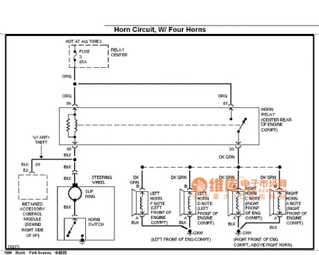
Buick speakers circuit diagram (Four horn)
Published:2011/5/6 1:34:00 Author:Jessie | Keyword: speakers
View full Circuit Diagram | Comments | Reading(602)
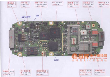
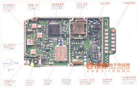
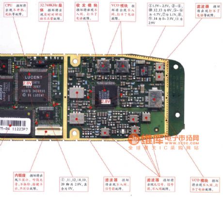
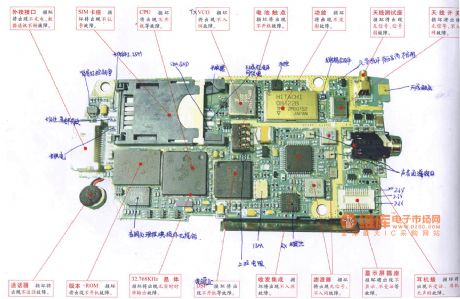
Nokia 6110 (5110) digital mobile phones relevant parts circuit diagram
Published:2011/5/6 1:33:00 Author:Jessie | Keyword: digital mobile phones
View full Circuit Diagram | Comments | Reading(787)
Simple hypnosis working principle circuit
Published:2011/5/6 1:31:00 Author:Jessie | Keyword: hypnosis
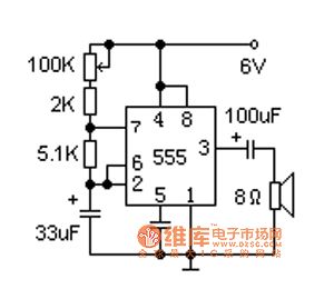
In this circuit, the time base circuit 555 conposes a very low frequency oscillator, and it outputs short pulses, which makes the speaker send out sound similar with raindrops. The speaker uses2 inches, 8 ohms small moving coil type. Raindrops soundspeed can be adjust to suitable degree by 100K potentiometer. Ifwe add a timing switch at power, so that can cut power in time when user asleep. (View)
View full Circuit Diagram | Comments | Reading(637)
Heat release infrared sensor induction control circuit 2
Published:2011/5/6 1:25:00 Author:Jessie | Keyword: Heat release infrared sensor, induction control
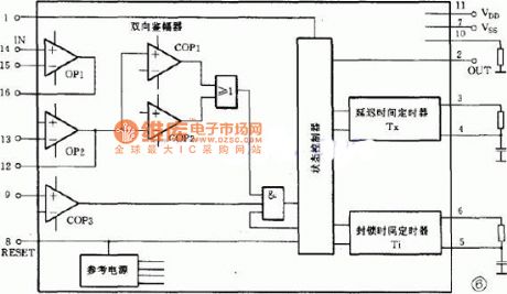
Photoconductive resistance R2 is used to detect environmental brightness, when the environment is bright, photoconductive resistance's value is smaller, it makes the pin 9 on low level, the output terminal 2 of pin IC1 is stable low level, switch tube deadline. If it needs to control circuit also can be used when environment is light, it just needs toremove R2. IC's pin 1 is thetriggered choice terminal, whenpin 1connects to high level, circuit works on repeatable; when pin 1 connects to grounding, circuit works on locking triggered. (View)
View full Circuit Diagram | Comments | Reading(531)
Pyroelectric infrared language alarm device principle circuit
Published:2011/5/6 1:19:00 Author:Jessie | Keyword: Pyroelectric infrared, language alarm device
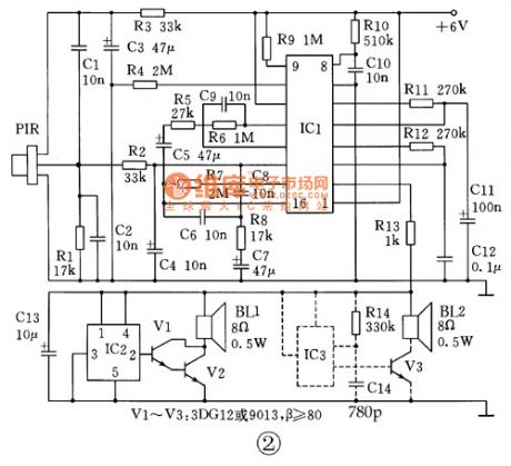
Pyroelectric infrared language alarm device circuit is shown in figure 2. Circuit is composed by pyroelectric infrared sensor, signal processing circuit and language alarm circuit. When people enter exclusionary area, pyroelectric infrared sensor (PIR) namely receive frequency 0 1 ~ 8Hz's infrared signal of the human body, and converts it into electrical signal, the resistance, capacitance C2 and C4 compose thelow pass filter circuits, filter high frequency interference noise, send to pin 14 of IC1, the signal is amplifered by internal level 2, after identified by two-way range in IC1, through the logic control circuit output high level from pin 2 of IC1, its time determined by R12, C12 in the circuit.
(View)
View full Circuit Diagram | Comments | Reading(689)
Vibration alarm circuit diagram
Published:2011/5/6 1:17:00 Author:Jessie | Keyword: Vibration alarm
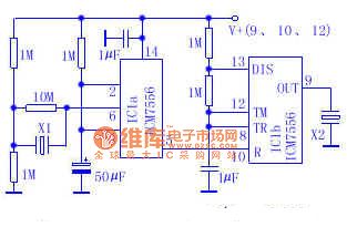
Using an integrated circuitIC7556, two piezoelectric ceramic clamps X1 and X2, and several passive electronic components to compose a mechanical vibration alarm, which can produce a minute of alarm sound. As long as exert mechanical vibration on piezoelectric ceramics piece X1, it will produce avoltage on IC1a's pin 610MΩ resistance. When triggered, 7556 makes piezoelectric ceramics piece X2 alarm sound. The second time basecircuit IC1b produces self-excited signal which is adjusted by 5Hz low-frequency.
(View)
View full Circuit Diagram | Comments | Reading(1233)
XS-Ⅱ electronic energy saving switch circuit diagram
Published:2011/5/5 22:59:00 Author:Jessie | Keyword: electronic, energy saving, switch

This switch is a touch delay electronic switch. Users touch metal M 1 second,lamp delaylighting 1-2 minutes; Users touch 2 seconds, the lamp ligting ≥ 3 minutes; Users touch 4 seconds, the lamp ligting ≥ 5 minutes.
(View)
View full Circuit Diagram | Comments | Reading(1882)
| Pages:178/312 At 20161162163164165166167168169170171172173174175176177178179180Under 20 |
Circuit Categories
power supply circuit
Amplifier Circuit
Basic Circuit
LED and Light Circuit
Sensor Circuit
Signal Processing
Electrical Equipment Circuit
Control Circuit
Remote Control Circuit
A/D-D/A Converter Circuit
Audio Circuit
Measuring and Test Circuit
Communication Circuit
Computer-Related Circuit
555 Circuit
Automotive Circuit
Repairing Circuit