
Index 176
CURRENT_TO_VOLTAGE_CONVERTER_WITH_BOOST_TRANSISTOR
Published:2009/6/23 1:38:00 Author:Jessie
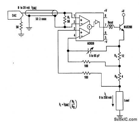
A transistor such as the MJE200 can be added to an Analog Devices AD830 to produce this current to voltage converter. Loads to 250 mA can be driven. The 5- to 65-pF trimmer is for compensation. (View)
View full Circuit Diagram | Comments | Reading(933)
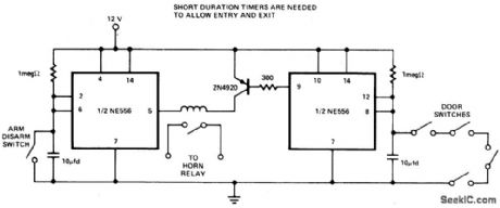
AUTO_BURGLAR_ALARM_1
Published:2009/6/22 23:50:00 Author:May
View full Circuit Diagram | Comments | Reading(0)
AUDIO_VOLUME_LIMITER
Published:2009/6/22 23:49:00 Author:May
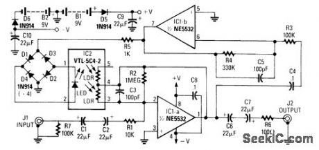
In this circuit,amplifier IC1-a provides signal amplification of 40 to+40 dB depending on thevalue of the LDR The LDR(ight dependent resistor)is driven by rectified audio from voltage follower IC1b and bridge rectifier D1 through D4 (View)
View full Circuit Diagram | Comments | Reading(0)
BLOWN_FUSE_ALARM
Published:2009/6/22 23:49:00 Author:May
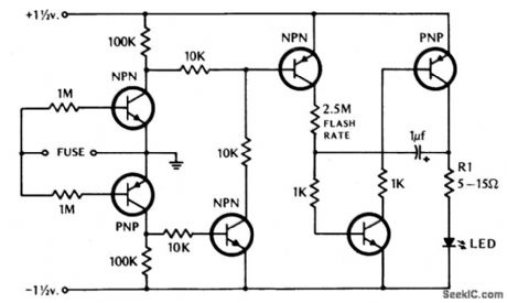
If the fuse blows, the LED indicator starts to blink. (View)
View full Circuit Diagram | Comments | Reading(0)
BOAT_ALARM
Published:2009/6/22 23:48:00 Author:May
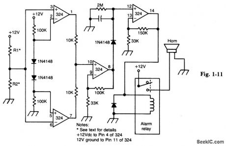
Removing R1 or R2 from the circuit (i.e., the potentiai thief breaks a hidden wire that connects R1 to +12 V and R2 to ground) activates the alarm for about five minutes. (View)
View full Circuit Diagram | Comments | Reading(821)
LATCHING_BURGLAR_ALARM
Published:2009/6/22 23:46:00 Author:May
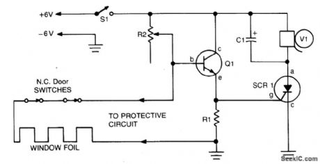
When the protective circuit is interrupted (opened), the alarm sounds. To set the circuit, adjust R2 (with protective circuit open) for 1 V across R1. (View)
View full Circuit Diagram | Comments | Reading(1079)
TAMPER_PROOF_BURGLAR_ALARM
Published:2009/6/22 23:45:00 Author:May
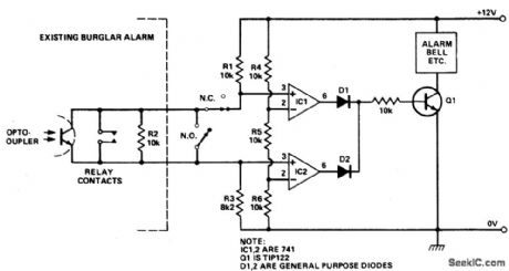
If R2 is opened or shorted, the alarm sounds. (View)
View full Circuit Diagram | Comments | Reading(637)
ANTITHEFT_DEVICE
Published:2009/6/22 23:43:00 Author:May
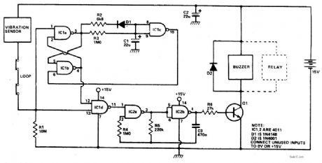
Any momentary break In the protective loop or tripping of the normally closed vibration sensor,causes alarm to sound for 20 seconds,If the circuit is open all the time,the alarm will sound continuously. (View)
View full Circuit Diagram | Comments | Reading(767)
SINE_WAVE_CONVERTER
Published:2009/6/22 23:54:00 Author:Jessie
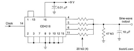
This circuit produces a sine wave with a low-frequency clock input. The clock rate should be 100Hz or less. (View)
View full Circuit Diagram | Comments | Reading(3700)
DRIVEN_FLYBACK_CONVERTER
Published:2009/6/22 23:53:00 Author:Jessie
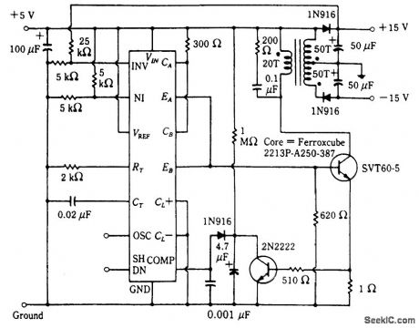
This circuit uses an SG1524 Silicon General regulating pulse width modulator and provides ±15 V from a 5-V supply rail. (View)
View full Circuit Diagram | Comments | Reading(1623)
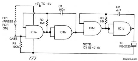
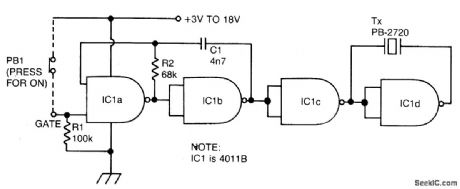
PULSED_TONE_ALARM,GATED_BY_A_HIGH_INPUT,WITH_DIRECT_DRIVE_OUTPUT
Published:2009/6/22 23:53:00 Author:Jessie
View full Circuit Diagram | Comments | Reading(1355)
12_BIT_DAC
Published:2009/6/22 23:52:00 Author:Jessie
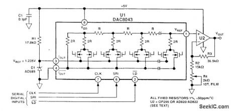
This circuit uses an Analog Devices DAC-8043 12-bit multiplying DAC The output will be D/4096×Vref where D is the numerical value of the digital input word(0 to 4095) Vref is 1.235 volts in this cicuit (View)
View full Circuit Diagram | Comments | Reading(2159)
CONTINUOUS_TONE_2_kHz_BUZZER_WITH_BRIDGE_DRIVE,GATED_ON_BY_A_LOGIC_0
Published:2009/6/22 23:51:00 Author:Jessie
View full Circuit Diagram | Comments | Reading(774)
AUTO_BURGLAR_ALARM_1
Published:2009/6/22 23:50:00 Author:Jessie
View full Circuit Diagram | Comments | Reading(1204)
SECURITY_ALARM
Published:2009/6/22 23:38:00 Author:May
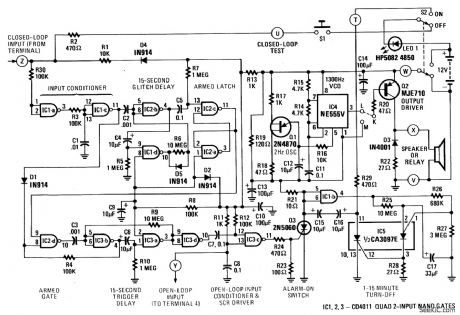
This alarm features open- and closed-loop detector and automatic alarm shutoff. Offers 15 second exit/entrance delay. Alarm on time can be adjusted from 1 to 15 minutes. (View)
View full Circuit Diagram | Comments | Reading(0)
BLOWN_FUSE_ALARM
Published:2009/6/22 23:49:00 Author:Jessie
If the fuse blows, the LED indicator starts to blink. (View)
View full Circuit Diagram | Comments | Reading(1330)
AUTOMOTIVE_BURGLAR_ALARM
Published:2009/6/22 23:35:00 Author:May
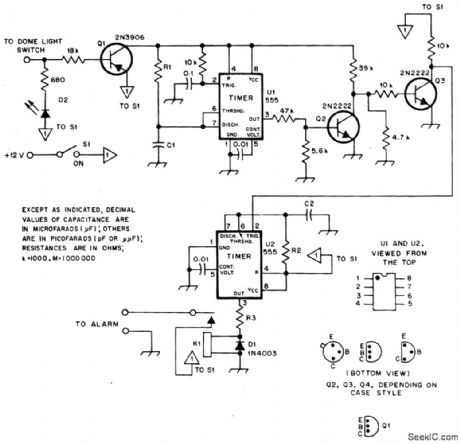
Alarm triggers on after a 13 second delay and stays on for 1-1 1/2 minutes. Then it resets automatically. It can also be turned off and reset by opening and reclosing S1. (View)
View full Circuit Diagram | Comments | Reading(0)
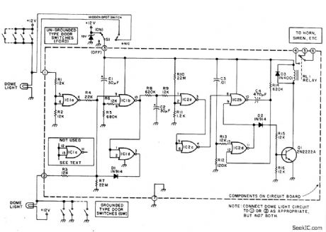
COMPUTALARM
Published:2009/6/22 23:25:00 Author:May
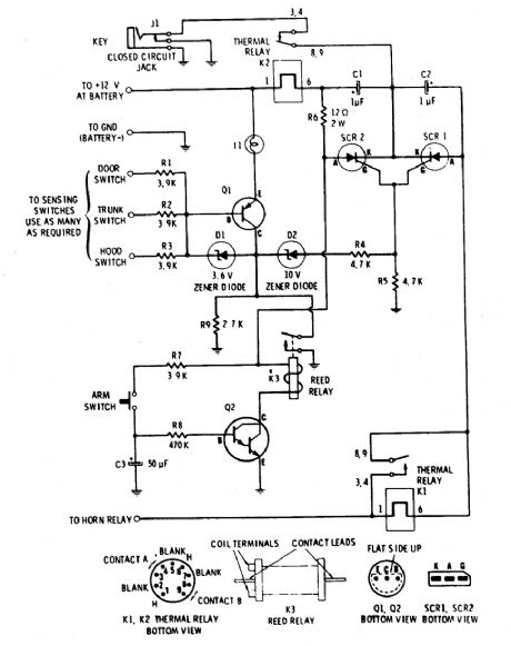
The circuit has a built-in, self-arming feature. The driver turns off the ignition, presses the arm button on the Computalarm, and leaves the car. Within 20 seconds, the alarm arms itself-all automatically! The circuit will then detect the opening of any monitored door, the trunk lid, or the hood on the car. Once acti-vated, the circuit remains dormant for 10 sec-onds. When the 10-second time delay has run out, the circuit will close the car's horn relay and sound the ham in periodic blasts (approxi-mately 1 to 2 seconds apart) for a period of one minute. Then the Computalarm automatically shuts itself off (to save your battery) and re-arms. If a door, the trunk lid, or the hood re-mains ajar, the alarm circuit retriggers and another period of horn blasts occurs. The Com-putalarm has a key switch by which the driver can disarm the alarm circuit within a 10-second period after he enters the door. The key switch consists of a closed circuit jack, J1, and a mating miniature plug. (View)
View full Circuit Diagram | Comments | Reading(0)
ELECTRONIF_THERMOSTAT
Published:2009/6/22 23:16:00 Author:May
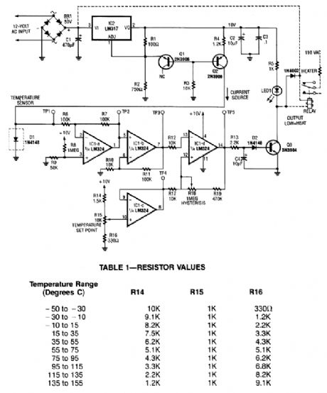
A diode, such as a IN4148, has a typical -2m V/℃ temperature coefficient at a 1 mA diode cur-rent. Q1 and Q2 form a constant current source. D1 is the temperature sensor. IC1-a and -b are dc amplifiers, with IC1-c a temperature reference voltage supply. IC1-d is a comparator with variable hysteresis. R14, R15, and R16 are chosen depending on the thermostat range desired. Q3 is a relay driver (2N3904). The relay used should handle the Ioad current or an optoisolator triac combination can be used. (View)
View full Circuit Diagram | Comments | Reading(0)
VEHICLE_SECURITY_SYSTEM
Published:2009/6/22 23:39:00 Author:Jessie
This alarm gives a 15-20 second exit and entrance delay. After being triggered, the alarm sounds for five minutes and then shuts off. Once triggered, the sequence is automatic and is not affected by subsequent opening or closing of doors. (View)
View full Circuit Diagram | Comments | Reading(1249)
| Pages:176/312 At 20161162163164165166167168169170171172173174175176177178179180Under 20 |
Circuit Categories
power supply circuit
Amplifier Circuit
Basic Circuit
LED and Light Circuit
Sensor Circuit
Signal Processing
Electrical Equipment Circuit
Control Circuit
Remote Control Circuit
A/D-D/A Converter Circuit
Audio Circuit
Measuring and Test Circuit
Communication Circuit
Computer-Related Circuit
555 Circuit
Automotive Circuit
Repairing Circuit