
Index 180
TURN_SIGNAL_ALARM
Published:2009/6/19 2:25:00 Author:May
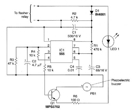
This circuit can be used to tell the driver of a vehicle when his or her turn signal has been left on for too long. The circuit consists of IC1, a 555 timer; transistor Q1, and MPS3702 PNP preamp/driver; PB1, a piezoelectric buzzer; along with an assortment of resistors, capacitors, and diodes. The 555 is connected in the mono.stable mode, requiring only a momentary negative pulse at pin 2 to trigger the timing cycle.Power for the circuit is picked off the flasher relay and applied to IC1, pin 8, provided by an ini-tially discharged capacitor, C2. After the initial triggering, the voltage across C2 rises as it becomes charged through R4, a 10-kΩ resistor. This prevents subsequent interference with the delay function caused by false triggering.Capacitor C3 and resistor R1 determine the delay. With the component values shown, a delay of about one minute will be provided before the intermittent tweet sound generated by the circuit be-gins. If higher values are used for C2 and R1, a longer delay time will result. The light-emitting diode, LED1, provides a voltage drop to assure complete transistor blocking during the off periods of the flasher. Alternatively, two diodes in series can be used. (View)
View full Circuit Diagram | Comments | Reading(1789)
Incandescent lamp life extension switch circuit 2
Published:2011/5/11 4:02:00 Author:May | Keyword: Incandescent lamp, life extension, switch
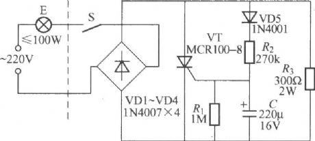
The diagram is shown in the diagram. Right hand of broken line in the diagram is life extension switch, left is ordinary light circuit, so lamp E and switch adopt two lines connection, namely single line input and output, it can directly replace ordinarily switch and does not need to change the original cabling indoor. (View)
View full Circuit Diagram | Comments | Reading(1462)
LOAD_DISCONNECT_SWITCH
Published:2009/6/19 2:22:00 Author:May
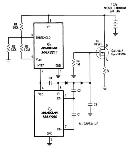
Deep discharge can damage a rechargeable battery. By disconnecting the battery from its load, this circuit halts battery discharge at a predetermined level of declining terminal voltage. Transistor Q1 acts as the switch. The overall circuit draws about 500 μA when the switch is closed and about 8 μA when the switch is open. (View)
View full Circuit Diagram | Comments | Reading(1228)
OSCILLATOR_TRIGGERED_SWITCH
Published:2009/6/19 2:20:00 Author:May
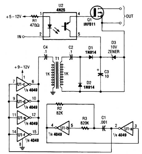
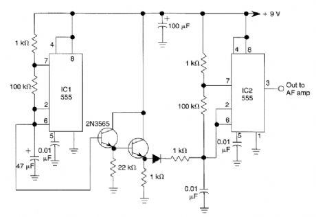
An oscillator is used here to generate a 9-V bias to switch Q1. This removes the need for a battery as a bias source. (View)
View full Circuit Diagram | Comments | Reading(1)
AUDIO_CONTROLLED_SWITCH
Published:2009/6/19 2:19:00 Author:May
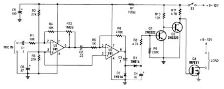
This audio-controlled switch combines a pair of 741 op amps, two 2N2222 general-purpose transistors, a hexFET, and a few support components to a circuit that can be used to turn on a tape recorder, a transmitter, or just about anything that uses sound. (View)
View full Circuit Diagram | Comments | Reading(0)
5G169 open-herding festival lantern larghing happily voice automatic control circuit
Published:2011/5/11 4:07:00 Author:May | Keyword: open-herding, festival lantern, larghing happily, voice automatic control

The circuit is shown in the diagram. It consists of starry carnival control circuit, laughter voice circuits, audio amplifier and rectifier voltage regulator, etc. (View)
View full Circuit Diagram | Comments | Reading(543)
ELECTRONIC_SAFETY_SWITCH
Published:2009/6/19 2:12:00 Author:May
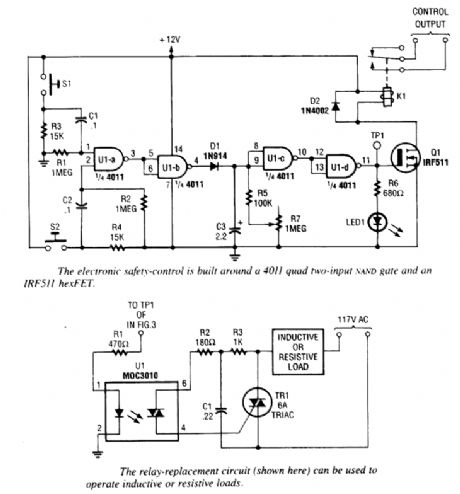
S1 and S2 must be depressed within 200 ms of each other to activate K1. The hold time is ad-justable via R7. S1 and S2 overlap time can be changed by changing C1 and C2 or R1 and R2. (View)
View full Circuit Diagram | Comments | Reading(689)
EIGHT_CHANNEL_AUDIO_SWITCHER
Published:2009/6/19 2:10:00 Author:May
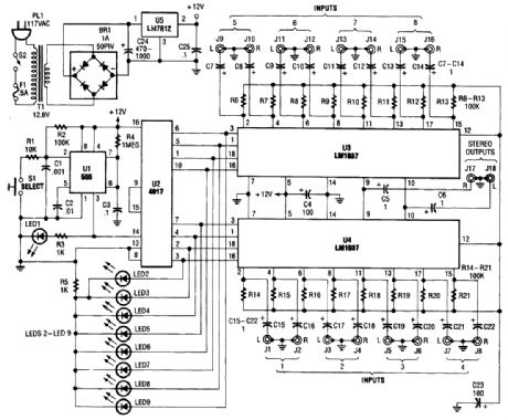
This source is selected by pressing momentary-contact pushbutton switch S1. Switch S1 is con-nected to the trigger of a 555 oscillator/timer (U1) configured as a monostable multivibrator, which generates one short output pulse for each press of S1. That pulse turns on LED1 to give a visible in-dication that the 555 is working correctly. That pulse is also used to clock U2 (a 4017 CMOS divide-by- 1 -counter/divider).Both LED1 and its associated current-limiting resistor R3 are optional and can be left out of the finished project without any affect on circuit operation. The 4017 advances by one clock pulse each time S1 is pressed, turning on its corresponding output. Pin 9 (corresponding to output 8) of U2 is directly connected to its own reset terminal at pin 15. This allows the counter to count from zero to seven, and then reset to zero on the eighth count.Pin 13, the enable input of U2, is tied to ground to allow the counter to operate. Outputs zero through seven are connected to eight indicator LEDs and the control pins of the two LM1037s (U3 and U4). When an output is selected, its LED lights and the corresponding control input on the LM1037 is brought high.The LM1037 has extremely high-impedance inputs and low-impedance outputs, so interconnec-tion between various types and brands of equipment should not be a problem. That, together with a wide-frequency response and low distortion, makes it ideal for use with good-quality, home-enter-tainment systems. The prototype of the audio switcher has a usable frequency response of from just a few hertz to over 100 kHz.Power for the switcher is provided by a rather simple circuit. Because the switcher only draws between 20 and 30 mA, a simple circuit using the popular 7812 or 78L12 (a low-power version) voltage regulator works quite well. (View)
View full Circuit Diagram | Comments | Reading(2906)
WIDEBAND_VIDEO_SWITCH_FOR_RGB_SIGNALS
Published:2009/6/19 2:03:00 Author:May
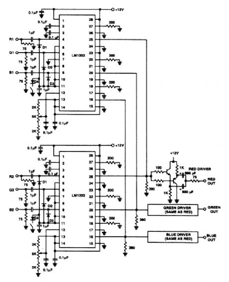
The switch shown selects 1to 2 inputs and uses a National LM1203. The slew rate is 4-V p-p into390 Ω in 5 to 7 ns. (View)
View full Circuit Diagram | Comments | Reading(740)
dc_CONTROLLED_SWITCH_USING_OPTOISOLATOR
Published:2009/6/19 2:00:00 Author:May
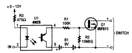
This dc-controlled switch uses an optoisola- tor/coupler, U1, to electrically isolate the input signal from the output-control device. (View)
View full Circuit Diagram | Comments | Reading(911)
SIMPLE_VIDEO_AUDIO_SWITCHER
Published:2009/6/19 1:59:00 Author:May
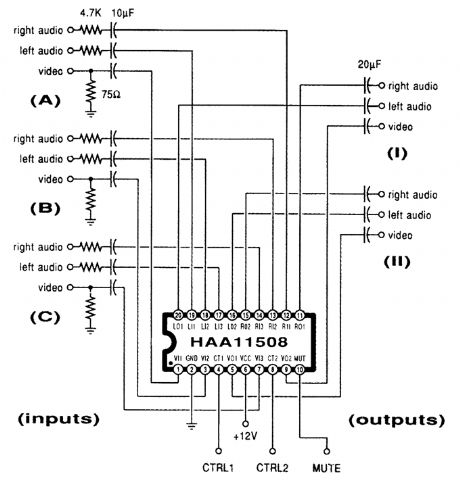
This channel selector selects video and stereo audio from any one ofthree different sources. The circuit should be constructed on a PC board with plenty of ground plane to minimize noise. (View)
View full Circuit Diagram | Comments | Reading(1858)
DUAL_CLOCK_CIRCUIT_FOR_STEPPER_MOTORS
Published:2009/6/18 23:41:00 Author:May
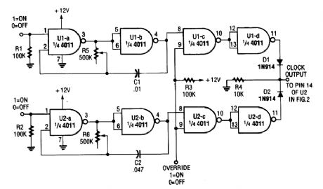
This oscillator can be used to drive a stepper motor circuit at two preset speeds with override to shut the motors off. (View)
View full Circuit Diagram | Comments | Reading(885)
ALTERNATE_TONE_ALARM
Published:2009/6/18 23:23:00 Author:May
A two-tone generator that is alternately switched ON provides a high/low output as might be heard from a traffic vehicle like a police car or ambulance.IC1, CD4011, quad 2-input NAND gate is a two-tone oscillator in which each side, pins 1 through 7 and 8 through 13 set the tone frequencies. Changing the values of C2 and C1 determines the high/low tones. The outout frequencies are coupled to IC2, CD4011, of which one side (pins 1 through 6) acts as a buffer. The buffer is necessary to prevent loading on the outputs that would occur if one tried to go directly to the LM386 amplifier. The other side of IC2, pins 8 through 13, is a slow pulse osciLator of approximately 8 Hz per second. The output at pin 10 is bonnected to IC4 as a clock.IC4, CD4027, is a dual J-K master-slave flip-flop that is wired to perform as a toggle switch in which Q1 and 15, and Q1 (NOT) pin 14, go high and low alternately (flip-flop). The clock input from IC2 pin 10 is connected to pin 13 of IC4, and the outputs at pins 15 and 14 changes the flip/flop state with each positive pulse transition. The CD4027 functions in toggle mode when the set and reset inputs, pins 9 and 12, are held low or grounded. Also, J-K inputs, pins 10 and 11, must be held high or to the positive.The outputs Q1 and Q1 (NOT), pins 15 and 14 are connected to pins 13 and 1 respectively oflC1 that enables or disables. Thus, each tone oscillator is turned on and off alternately. IC3 is a straightforward low-voltage audio amplifier. (View)
View full Circuit Diagram | Comments | Reading(1773)
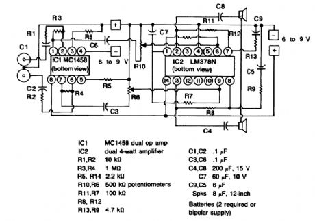
SIREN
Published:2009/6/18 23:12:00 Author:May
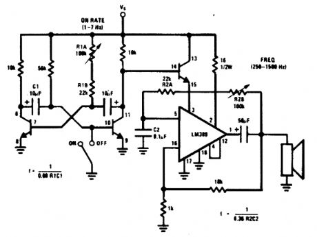
An LM380 audio IC is configured as a feed-transistor astable modu-a low frequency, which back audio oscillator. A lates this oscillator at a low frequency, which produces a siren tone. (View)
View full Circuit Diagram | Comments | Reading(2)
Photoelectric automatic controller circuit diagram
Published:2011/6/23 22:26:00 Author:Rebekka | Keyword: Photoelectric automatic controller
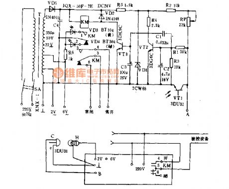
Photoelectric automatic controller is - kind of fast action of light control devices. It is used for the automatic start, automatic stop hunger, moving the door to protect from power counting, automatic alarm, etc. It is suitable for mechanical instruments, metallurgy, textile, paper and other production processes. Its working principle is shown as below. 220V AC passes T Buck and secondary turns into 22V. A stable voltage provided for VT2 regulated by the VD5, C4 rectifier, VDl. When the VT1 element photodiode is exposed to light, it passes the resistance and make the vT2 base key rise. The VT2 turns into saturation mode. (View)
View full Circuit Diagram | Comments | Reading(558)
SPACESHIP_ALARM
Published:2009/6/18 22:51:00 Author:May
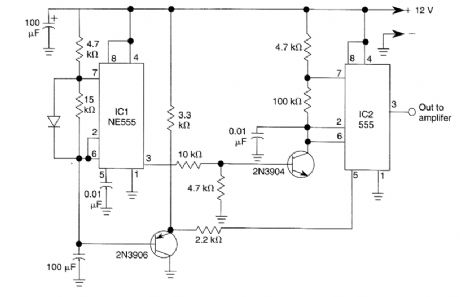
By using two 555 timers this circuit produces a low frequency tone that rises to a high frequency tone in a little over 1 second. Then the sound stops for about 0.3 seconds, thereafter the cycle re-peats. To produce the alarm sound of the Star Trek spaceship. (View)
View full Circuit Diagram | Comments | Reading(1029)
1000_Hz_PULSED_TONE_ALARM
Published:2009/6/18 22:48:00 Author:May
IC1 generates a pulse that modulates the 1000-Hz tone generated by IC2. This circuit can be used to generate warning or alert signals. (View)
View full Circuit Diagram | Comments | Reading(810)
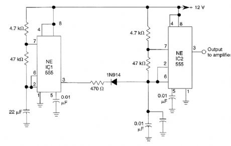
SIREN_ALARM
Published:2009/6/18 22:48:00 Author:May
The ramp voltage from the low frequency oscillator IC1 modulates IC2 thereby producing a rising and falling tone like the siren wail of police cars. (View)
View full Circuit Diagram | Comments | Reading(987)
AUDIO_CONTROLLED_MAINS_SWITCH
Published:2009/6/18 22:40:00 Author:May
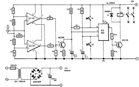
This circuit will switch off the line supply to audio or video equipment if there has been no input signal for about 2 seconds. S1 provides manual operation and S2 acts as a reset. This circuit allows for time to change a tape or compact disc. About 50 mV of audio signal is necessary. (View)
View full Circuit Diagram | Comments | Reading(730)
AUDIO_CONTROLLED_SWITCH
Published:2009/6/18 22:32:00 Author:May
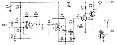
The audio-controlled switch combines a pair of 741 op amps, two 2N2222 general-purpose tran-sistors, a hexFET, and a few support components to a circuit that can be used to turn on a tape recorder, a transmitter, or just about anything that uses sound. (View)
View full Circuit Diagram | Comments | Reading(4)
| Pages:180/312 At 20161162163164165166167168169170171172173174175176177178179180Under 20 |
Circuit Categories
power supply circuit
Amplifier Circuit
Basic Circuit
LED and Light Circuit
Sensor Circuit
Signal Processing
Electrical Equipment Circuit
Control Circuit
Remote Control Circuit
A/D-D/A Converter Circuit
Audio Circuit
Measuring and Test Circuit
Communication Circuit
Computer-Related Circuit
555 Circuit
Automotive Circuit
Repairing Circuit