
Switch Control
Index 15
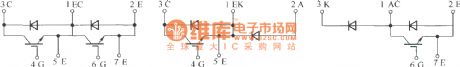
GA series IGBT half bridge, high side switch and low side switch type module cut-away drawing
Published:2011/4/8 2:05:00 Author:may | Keyword: IGBT half bridge, high side switch, low side switch, cut-away drawing
View full Circuit Diagram | Comments | Reading(730)
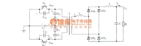
Soft switching schematic circuit diagram
Published:2011/4/2 3:52:00 Author:may | Keyword: soft switching
View full Circuit Diagram | Comments | Reading(790)
IR2110 pin array and internal function principle block diagram
Published:2011/4/7 3:47:00 Author:may | Keyword: pin array, internal function principle
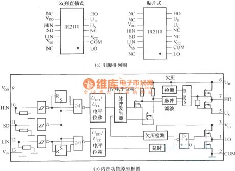
IR2110 is a kind of two-channel high voltage, high speed voltage type power switch device grid driver. It has boot floating power. Its drive circuit is very simple. It only use one way power supply and can drive up and down bridge arms at the same time. It can not generate negative, and is weak in anti-interference. (View)
View full Circuit Diagram | Comments | Reading(4417)
Lights in building passageway automatically delay turning off circuit diagram
Published:2011/4/6 3:49:00 Author:Ecco | Keyword: Lights in building passageway, automatically delay , turning off
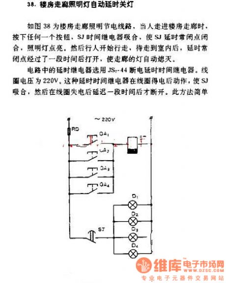
Lights inbuilding passageway automatically delay turning off
Figure 38 is saving circuit of the building corridor lighting, when people walk into the building corridor, press any buttons, SJ relay closes, delay normally closed point of SJ closes, lamp turns on, and then people start walking, until get indoors, the delay normally closed point opens after a period of closing time, so that the corridor lights automatically turns off. The time delay relay in the circuit uses JS7-44 power-off delay time relay. Coil voltage is 220V. The power-off delay time relay works after the coil gets electricity, and make SJ closes, and breakes in a delay time after the coil being power-off. This method is simple. (View)
View full Circuit Diagram | Comments | Reading(1044)
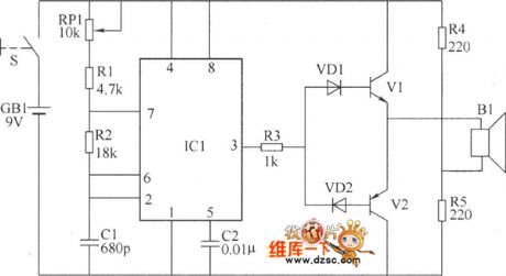
Voice control delay switch circuit
Published:2011/3/27 22:31:00 Author:may | Keyword: Voice control delay switch
Voice control delay switch circuit is shown in the diagram:
(View)
View full Circuit Diagram | Comments | Reading(977)
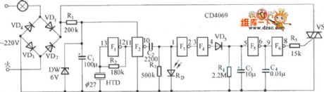
Ultrasonic principle remote control switch circuit
Published:2011/3/27 21:53:00 Author:may | Keyword: Ultrasonic principle remote control switch
Ultrasonic principle remote control switch circuit is shown in the diagram:
(View)
View full Circuit Diagram | Comments | Reading(814)
Voice control switch circuit
Published:2011/3/23 2:52:00 Author:Joan | Keyword: Voice control , switch
Below is the Voice control switch circuit.
(View)
View full Circuit Diagram | Comments | Reading(1537)
Triple key interlock electronic switch schematic
Published:2011/3/17 19:59:00 Author:Joan | Keyword: Triple key, interlock , electronic switch
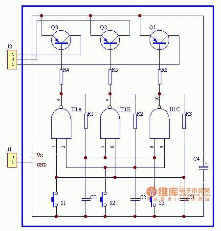
The figure is Triple key interlock electronic switch schematic.
(View)
View full Circuit Diagram | Comments | Reading(3088)
| Pages:15/15 123456789101112131415 |
Circuit Categories
power supply circuit
Amplifier Circuit
Basic Circuit
LED and Light Circuit
Sensor Circuit
Signal Processing
Electrical Equipment Circuit
Control Circuit
Remote Control Circuit
A/D-D/A Converter Circuit
Audio Circuit
Measuring and Test Circuit
Communication Circuit
Computer-Related Circuit
555 Circuit
Automotive Circuit
Repairing Circuit