
Switch Control
Index 12
DUAL_CONTROL_HEXFET_SWITCH
Published:2009/6/19 2:33:00 Author:May
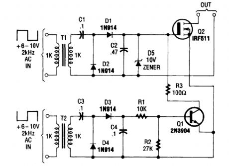
This dual-control switch uses two 6 to 10-Vac sources to trigger the circuit on and off; one source for each function. (View)
View full Circuit Diagram | Comments | Reading(719)
REMOTE_TWO_WAY_ac_SWITCH_HOOkUP
Published:2009/6/19 2:28:00 Author:May
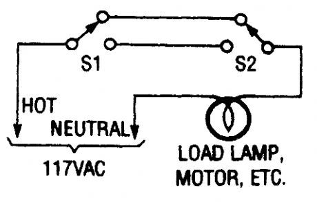
This switching arrangement is the type of arrangement used in both domestic and industrial environments to allow a light or other ac-operated device to be controlled from more than one location (View)
View full Circuit Diagram | Comments | Reading(699)
dc_CONTROLLED_FET_SWITCH
Published:2009/6/19 2:28:00 Author:May
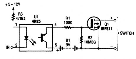
This dc-controlled switch uses an optoisolator/coupler, U1, to electrically isolate the input signal from the output-control device. (View)
View full Circuit Diagram | Comments | Reading(1568)
HEXFET_SWITCH
Published:2009/6/19 2:27:00 Author:May
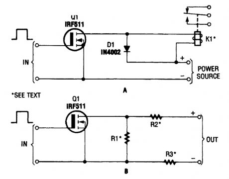
The hexFET can switch dc power to relays (as shown in A), motors, lamps, and numerous other devices. That arrangement can even be used to switch resistors in and out of a circuit, as shown in B. R1, R2, and R3 represent resistive loads that can be switched in and out of the circuit. (View)
View full Circuit Diagram | Comments | Reading(1128)
Incandescent lamp life extension switch circuit 2
Published:2011/5/11 4:02:00 Author:May | Keyword: Incandescent lamp, life extension, switch
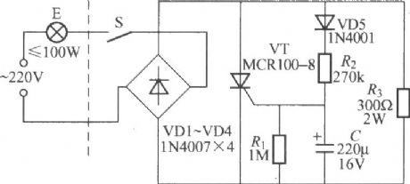
The diagram is shown in the diagram. Right hand of broken line in the diagram is life extension switch, left is ordinary light circuit, so lamp E and switch adopt two lines connection, namely single line input and output, it can directly replace ordinarily switch and does not need to change the original cabling indoor. (View)
View full Circuit Diagram | Comments | Reading(1474)
LOAD_DISCONNECT_SWITCH
Published:2009/6/19 2:22:00 Author:May
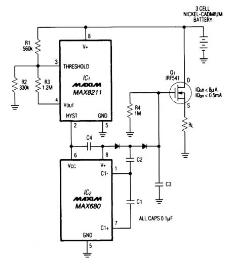
Deep discharge can damage a rechargeable battery. By disconnecting the battery from its load, this circuit halts battery discharge at a predetermined level of declining terminal voltage. Transistor Q1 acts as the switch. The overall circuit draws about 500 μA when the switch is closed and about 8 μA when the switch is open. (View)
View full Circuit Diagram | Comments | Reading(1248)
OSCILLATOR_TRIGGERED_SWITCH
Published:2009/6/19 2:20:00 Author:May
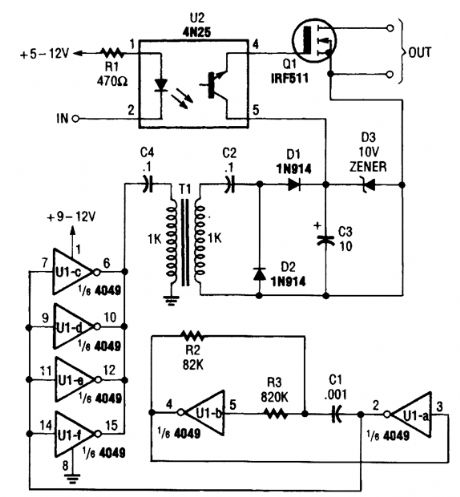
An oscillator is used here to generate a 9-V bias to switch Q1. This removes the need for a battery as a bias source. (View)
View full Circuit Diagram | Comments | Reading(1)
AUDIO_CONTROLLED_SWITCH
Published:2009/6/19 2:19:00 Author:May
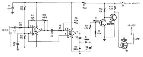
This audio-controlled switch combines a pair of 741 op amps, two 2N2222 general-purpose transistors, a hexFET, and a few support components to a circuit that can be used to turn on a tape recorder, a transmitter, or just about anything that uses sound. (View)
View full Circuit Diagram | Comments | Reading(0)
ELECTRONIC_SAFETY_SWITCH
Published:2009/6/19 2:12:00 Author:May
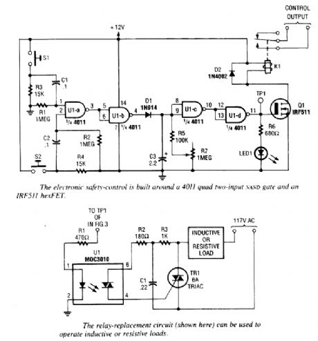
S1 and S2 must be depressed within 200 ms of each other to activate K1. The hold time is ad-justable via R7. S1 and S2 overlap time can be changed by changing C1 and C2 or R1 and R2. (View)
View full Circuit Diagram | Comments | Reading(713)
EIGHT_CHANNEL_AUDIO_SWITCHER
Published:2009/6/19 2:10:00 Author:May
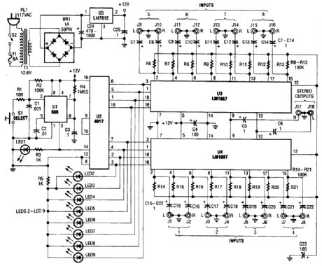
This source is selected by pressing momentary-contact pushbutton switch S1. Switch S1 is con-nected to the trigger of a 555 oscillator/timer (U1) configured as a monostable multivibrator, which generates one short output pulse for each press of S1. That pulse turns on LED1 to give a visible in-dication that the 555 is working correctly. That pulse is also used to clock U2 (a 4017 CMOS divide-by- 1 -counter/divider).Both LED1 and its associated current-limiting resistor R3 are optional and can be left out of the finished project without any affect on circuit operation. The 4017 advances by one clock pulse each time S1 is pressed, turning on its corresponding output. Pin 9 (corresponding to output 8) of U2 is directly connected to its own reset terminal at pin 15. This allows the counter to count from zero to seven, and then reset to zero on the eighth count.Pin 13, the enable input of U2, is tied to ground to allow the counter to operate. Outputs zero through seven are connected to eight indicator LEDs and the control pins of the two LM1037s (U3 and U4). When an output is selected, its LED lights and the corresponding control input on the LM1037 is brought high.The LM1037 has extremely high-impedance inputs and low-impedance outputs, so interconnec-tion between various types and brands of equipment should not be a problem. That, together with a wide-frequency response and low distortion, makes it ideal for use with good-quality, home-enter-tainment systems. The prototype of the audio switcher has a usable frequency response of from just a few hertz to over 100 kHz.Power for the switcher is provided by a rather simple circuit. Because the switcher only draws between 20 and 30 mA, a simple circuit using the popular 7812 or 78L12 (a low-power version) voltage regulator works quite well. (View)
View full Circuit Diagram | Comments | Reading(2922)
WIDEBAND_VIDEO_SWITCH_FOR_RGB_SIGNALS
Published:2009/6/19 2:03:00 Author:May
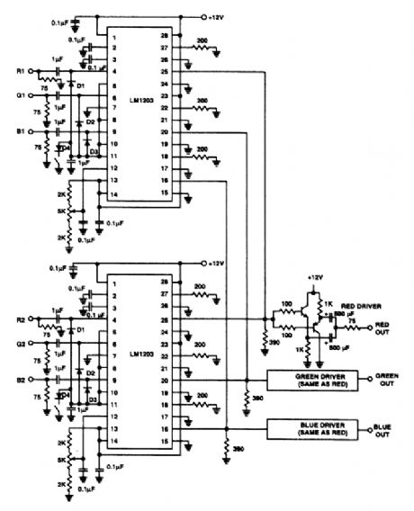
The switch shown selects 1to 2 inputs and uses a National LM1203. The slew rate is 4-V p-p into390 Ω in 5 to 7 ns. (View)
View full Circuit Diagram | Comments | Reading(753)
dc_CONTROLLED_SWITCH_USING_OPTOISOLATOR
Published:2009/6/19 2:00:00 Author:May
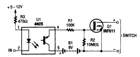
This dc-controlled switch uses an optoisola- tor/coupler, U1, to electrically isolate the input signal from the output-control device. (View)
View full Circuit Diagram | Comments | Reading(930)
SIMPLE_VIDEO_AUDIO_SWITCHER
Published:2009/6/19 1:59:00 Author:May
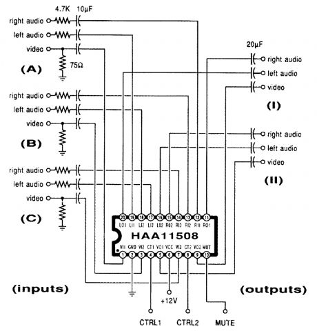
This channel selector selects video and stereo audio from any one ofthree different sources. The circuit should be constructed on a PC board with plenty of ground plane to minimize noise. (View)
View full Circuit Diagram | Comments | Reading(1883)
AUDIO_CONTROLLED_MAINS_SWITCH
Published:2009/6/18 22:40:00 Author:May
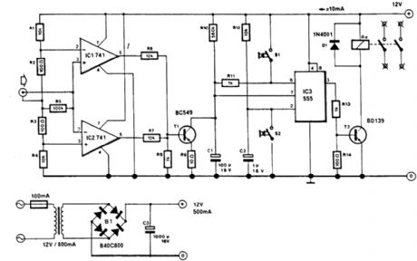
This circuit will switch off the line supply to audio or video equipment if there has been no input signal for about 2 seconds. S1 provides manual operation and S2 acts as a reset. This circuit allows for time to change a tape or compact disc. About 50 mV of audio signal is necessary. (View)
View full Circuit Diagram | Comments | Reading(747)
AUDIO_CONTROLLED_SWITCH
Published:2009/6/18 22:32:00 Author:May
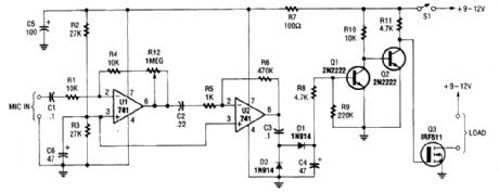
The audio-controlled switch combines a pair of 741 op amps, two 2N2222 general-purpose tran-sistors, a hexFET, and a few support components to a circuit that can be used to turn on a tape recorder, a transmitter, or just about anything that uses sound. (View)
View full Circuit Diagram | Comments | Reading(4)
WHISTLE_SWITCH
Published:2009/6/18 22:29:00 Author:May
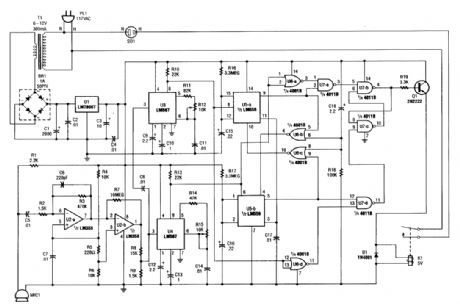
At the heart of the whistle switch are a pair of tone detectors, each of which is built around an LM567 tone decoder, which are supported by a ntinimum of additional components. This whistle switch is designed to respond to only two or more occur-rences of a specific tone, or sequence of tones, within a specified period to prevent false triggering. Depending on the relay used, various ac loads can be controlled. Microphone MIC1 picks up the sound and U2 amplifies the signal and feeds it to tone decoders U3 and U4. These devices trigger U5-a and U5-b and the logic circuits that drive relay K1. (View)
View full Circuit Diagram | Comments | Reading(2065)
LATCHING_TOUCH_SWITCH_USING_CD4066B
Published:2009/6/18 4:13:00 Author:May
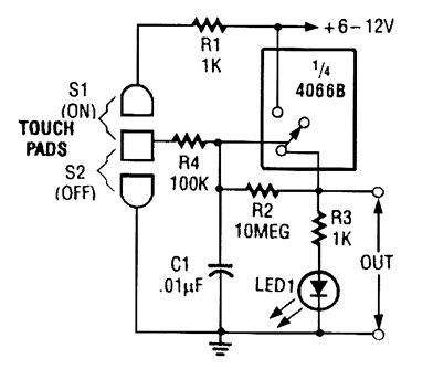
When touch switch S1 is activated, R4 is driven high, and the control voltage goes high, which latches the switch. When S2 is activated, R4 goes low and the control voltage goes low, which deactivates the switch. (View)
View full Circuit Diagram | Comments | Reading(944)
TOUCH_ON_ONLY_SWITCH
Published:2009/6/18 4:11:00 Author:May
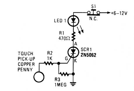
This touch on-only switch can be triggered into conduction by electrical means, and can only be reset by way of a mechanical switch. When the touch terminal is contacted by a finger, the SCR turns on and illuminates LED1. (View)
View full Circuit Diagram | Comments | Reading(872)
TOUCH_SWITCH_II
Published:2009/6/18 4:10:00 Author:May
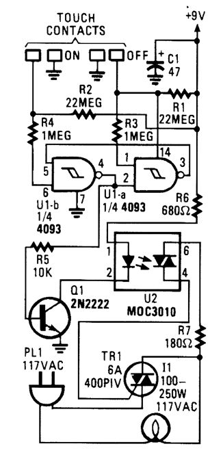


When the touch-on contacts are bridged, pin 6 of U1-b goes low, which forces its output (the set output) at pin 4 to go high. That high divides along two paths: in one path, the output is applied to pin 2 of UI-a, which causes its out-put at pin 3 to go low. That low is, in turn, ap-plied to pin 5 of UI-b, which latches the gate in a high output state. In the other path, the out-put of U1-b is used to drive Q1. When Q1 turns on, U2's internal LED lights, which turns on its internal, light-sensitive, triac-driver (diac) out-put element. The triac driver feeds gate current to TRI, causing it to turn on, and light the lamp (11).When the off contact is bridged, UI-a's out-put switches and latches high, causing UI-b's output to go low, turning off the lamp. (View)
View full Circuit Diagram | Comments | Reading(377)
TOUCH_SWITCH_I
Published:2009/6/18 4:04:00 Author:May
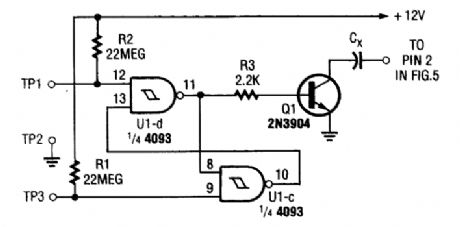
Two NAND Schmitt triggers are connected in a flip-flop configuration to produce a bridged touch-activated switch. (View)
View full Circuit Diagram | Comments | Reading(1136)
| Pages:12/15 123456789101112131415 |
Circuit Categories
power supply circuit
Amplifier Circuit
Basic Circuit
LED and Light Circuit
Sensor Circuit
Signal Processing
Electrical Equipment Circuit
Control Circuit
Remote Control Circuit
A/D-D/A Converter Circuit
Audio Circuit
Measuring and Test Circuit
Communication Circuit
Computer-Related Circuit
555 Circuit
Automotive Circuit
Repairing Circuit