
Switch Control
Index
Dongfeng Peugeot Citroen Picasso 2.0L car door switch information circuit
Published:2014/1/23 20:29:00 Author:lynne | Keyword: Dongfeng Peugeot Citroen Picasso 2.0L car door switch information circuit,
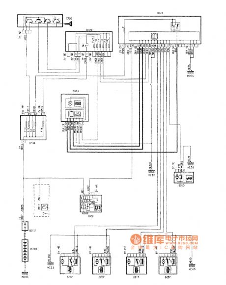
Dongfeng Peugeot Citroen Picasso 2.0L car door switch information circuit shown in Figure:
(View)
View full Circuit Diagram | Comments | Reading(1502)
Soft switching circuit schematic circuit diagram
Published:2014/1/21 21:10:00 Author:lynne | Keyword: Soft switching circuit schematic circuit diagram,
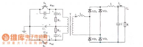
Soft switching circuit schematic circuit diagram shown in Fig.:
(View)
View full Circuit Diagram | Comments | Reading(1169)
TILT SWITCH
Published:2013/8/1 22:27:00 Author:lynne | Keyword: TILT SWITCH
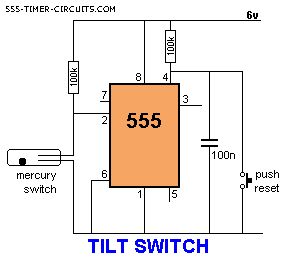
The output is LOW at start-up due to the capacitor on pin 4. When the mercury switch closes, the output goes HIGH and remains HIGH until the reset button is pressed. This circuit is called a LATCH. (View)
View full Circuit Diagram | Comments | Reading(1263)
TOUCH SWITCH and TOUCH ON-OFF
Published:2013/8/1 22:25:00 Author:lynne | Keyword: TOUCH SWITCH and TOUCH ON-OFF
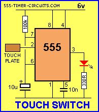
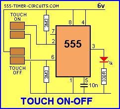
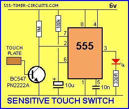
The Touch Switch circuit will detect stray voltages produced by mains voltages and electrostatic build-up in a room. In the first circuit, pin 2 must see a LOW for the circuit to activate. If sufficient static voltage is detected by the plate, the chip will change state. If not, you will need to touch the plate and the 0v rail. In the second circuit, two touch plates are provided and the resistance of your finger changes the voltage on pin 2 or 6 to toggle the 555.
The circuit can be made 100 times more sensitive by adding a transistor to the front-end as shown in the diagram below:
(View)
View full Circuit Diagram | Comments | Reading(3115)
Security Light & Switch with PIR Sensor
Published:2012/9/25 21:31:00 Author:muriel | Keyword: Security, Light, Switch, PIR Sensor
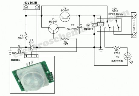
SB0061 is a pyroelectric sensor module,developed for human body detection. A PIR detector combined with a fresnel lens are mounted on a compact size PCB together with an analog IC (SB0061) and limited components to form the module. High level output (3.3V) of pre-settable variable width (5Secs -18 Minutes) is provided.
Circuit diagram of the PIR Motion Sensor Light and Switch based on SB0061 shown here can be used for security or corridor lighting in power saving mode. The 12V DC supply required for the whole circuit can be fed from any standard 12V ac mains adaptor/battery.
Working of the circuit is simple and straight forward. When any movement is detected within near 5-6 metres, around 3.3 Volt is appeared at the base of Transistor T1 and it conducts to fire the next relay driver transistor T2. As a result, the 12V DPDT relay is energised to power the White LED through current limiting resistor R3. Spare relay contacts can be used as a switch to control any suitable external load. The white LED and the relay remains ON for a duration based on the mono time setting in SB0061, ie from 5 Secs to 18 Minutes.
PIR Motion Sensor Circuit Schematic
(View)
View full Circuit Diagram | Comments | Reading(3968)
Power switch with infrared proximity sensor
Published:2012/9/25 1:04:00 Author:muriel | Keyword: Power switch,infrared,proximity sensor
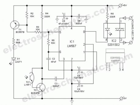

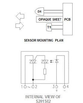
The power switch with infrared proximity sensor is intended for the recognition of obstructions at distances of a few millimetres to a few centimetres. This compact sensor switch can be used to open a water tap via a solenoid valve. In our circuit, the proximity sensor assembly is built from a discrete infrared light emiting diode (LD271-from Siemens/Osram) and a phototransitor (L14F1). A solid-state relay (S201S02-from Sharp) at the output of the circuit enables larger ac mains operated loads (for instance, the solenoid valve) to be switched.
How the infrared switch is working
At the heart the circuit is one renowned phase locked loop tone decoder chip (LM567 from NSC). When the pulsed infrared light signal from D1 is reflected by a nearby object, phototransistor T2 -through T3- provides a signal to pin 3 of IC1. If the signal frequency lies within the same band as that of the internal generator, output terminal (pin8) of IC1 is connected to earth, where upon LED in the solid-state relay (IC2) lights and the relay is energised.
Infrared Power Switch Circuit Diagram
Infrared proximity sensor compornents and parts
(View)
View full Circuit Diagram | Comments | Reading(1908)
Bathroom door control switch circuit ( 2 )
Published:2012/9/18 2:04:00 Author:Ecco | Keyword: Bathroom , door control switch
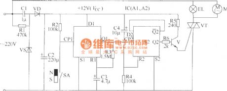
The circuit is used to control the bathroom lights and exhaust fan. When someone opens the door and comes to the bathroom, the door control switch is turned on, the bathroom light will be lit and exhaust fan is also energized; When users open the door and come out of the bathroom, the door control switch is turned off, lights will be turned off, the exhaust fan is also interrupted.The bathroom door control switch circuit inlcudes the power circuit, monostable flip-flop, flip-flop circuit and control execution, and it is shown in the figure.
(View)
View full Circuit Diagram | Comments | Reading(1386)
Delay switch circuit with thyristor
Published:2011/8/29 2:01:00 Author:Jessie | Keyword: delay switch circuit
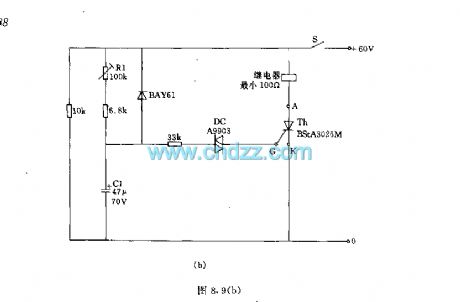
Delay switch circuit with thyristorcan control the connect and disconnect of high-power appliances. The delaying accuracy of the Figure (a) depends on regulator. Figure (b) uses two-way diode A9903 or TV503 to replace the tetrode BRY20 in Figure (a). Technical parameters: 60V ± 10%; maximum load resistor RL: 860Ω, the minimum load resistor RL: 100Ω, delay time: 0.3 ~ 3.6S.
(View)
View full Circuit Diagram | Comments | Reading(2037)
Light contrtol switch circuit using TRIAC
Published:2011/11/10 1:46:00 Author:May | Keyword: Light contrtol switch, TRIAC
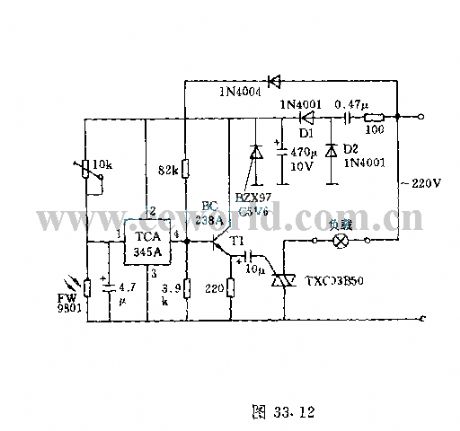
Light contrtol switch circuit adopts bidirectional thyristor. This circuit can control make-and-break of 200W power load on 220V AC network . If the power is only 50W, bidirection thyrisotr can not connect radiator. The action point with some hysteresishas about 100lx sun light. When light is weak, thephotoresistor presents high resistance, then the threshold switch TCA345's input voltage ishigher than 0.7 times of pin 2's voltage , and thethreshold switch output end is in high resistance value,then it is breakover bytransistor period triggering bidirectional thyristor. Contrarily, if surrounding light exceeds100lx, threshold switch output end changes to negative, at this time, proclitic transistor and bidirectional thyristor arecut-off, then lamp goes out.
Diodes D1 and D2 in the circuit areused for rectification, and it outputs about 15mA controlling current. (View)
View full Circuit Diagram | Comments | Reading(2180)
Light control switch using photoresistor
Published:2011/11/10 1:52:00 Author:May | Keyword: Light control switch, photoresistor
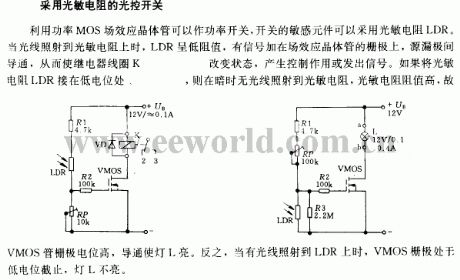
It utilizes power MOS FET as power switch, and the witch sensing element can adopt photoresistor LDR. Whenlight shines on photoresistor, LDR presenst low resistance,andwhen there issignal addingto thegrid of FET, the source-drain is conducted tomake relay coil K change state andgenerate controlling usage or signal. Ifthe photoresistor LDR is connected to low-level position, when it is dark and has no light shining on photoresistor, then the value of photoresistor is high, so VMOS's grid level is high to make lamp L be bright. Reversely, whenthere islight shining on LDR, VMOS grid is inlow level and closed, lamp L isnot bright.
(View)
View full Circuit Diagram | Comments | Reading(1548)
Semiconductor analog switch circuit
Published:2011/12/1 1:33:00 Author:May | Keyword: Semiconductor, analog switch
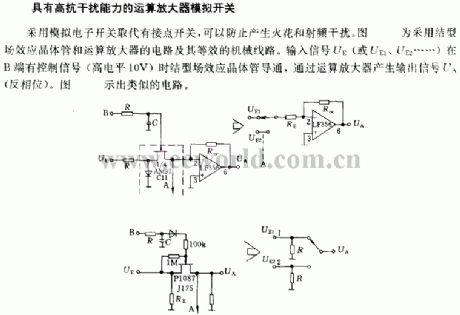
High noise immunity operational amplifier analog switch
It uses theanalog electronic switching to replace contact switch, and itcan prevent sparkle and radio interference. The diagram is the circuit using junction field effect transistor and operational amplifier and its equivalent machiinery track. When input signal UE ( or UE1, UE2...) has control signal ( high level 10V) , junction field effect transistor is breakover, and it output signal UA ( anti-phase)through operational amplifier. Diagram shows the similar circuit.
(View)
View full Circuit Diagram | Comments | Reading(911)
Electronic self-locking interlock switch circuit diagram
Published:2011/10/31 3:32:00 Author:May | Keyword: Electronic self-locking interlock switch

Switch's core component is the four operational amplifier LM324, after the ingenious design, each operational amplifier has the twofold function like the voltage comparator and the Schmitt trigger. The voltage applicable scope is wide, and the files may be designed willfully, if it adds a neutral gear, it can be used as the overall reset, when it is used with the digital circuit, they can use the same power source, and the switch's input, output level conforms to digital circuit's connection level, because operational amplifier has high input impedance, the switch's input current is small, it may use the light touching switch. The conductive rubber, thin film switch makes the pressing key. (View)
View full Circuit Diagram | Comments | Reading(2387)
Electronic light touch switch circuit
Published:2011/10/27 21:10:00 Author:May | Keyword: Electronic light touch switch
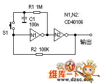
Bistable circuit is a kind of circuit we often use. It is always usedas one-button controlling switchin various circuits.
Working principle: If N1 input end starts in high level, then N2 output also is in high level, then R2 makes the circuit output the high level stably. At this time, because the N1's output port is in low level, therefore C1 discharges by R1. After pressing down S1, N1's input end changes to the low level, the N2's input rises, the N2's output changes to the low level, then the circuit reverses to output the low level stably, and C1 charges by R1. If pressesing S1 again, the circuit returns to another steady state. (View)
View full Circuit Diagram | Comments | Reading(1150)
Password Electronic Switch Circuit Diagram
Published:2011/10/23 20:58:00 Author:May | Keyword: Password Electronic Switch
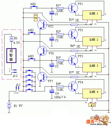
The working principle of this device is shown in the diagram. This password electronic switchhas three unlock buttons, and it also has the timelimiting circuit, error lock and electronic alarm circuit. It can make relay J1 excited pull in only by pressing unlock buttons AN1, AN2, AN3 correctly. The pick-up time is determined by the value of R1 and C1. In the diagram, transistors VT5, VT6, VT7 are cascaded into an AND gate circuit. When one of the three transistorsis cut off, the relay J1 will release. The five buttons AN1-AN8 are spliced into an OR gate logic circuit. It can cause the breaking over of transistor VT4. Then LSE's pin 1 and 2are broken over, and its pin 4 outputs high level, and relay J2 is excited and pulled in. Its locking time is determined by the value of R4 and C4.
(View)
View full Circuit Diagram | Comments | Reading(2253)
Infrared delay light switch circuit diagram
Published:2011/9/27 1:33:00 Author:Rebekka | Keyword: Infrared delay light switch
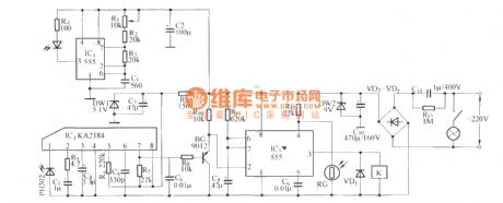
KA2184 infrared receiver integrated circuit ismade in the Korean. The performance, parameters and pin functions are identical with the CX20106.They can be directly used interchangeably. Since the circuit uses infrared reflective circuit structure. So infrared transmitter and receiver need to be installed in the same direction and in the same plane. It makes the transmitter and the receiver become integrated structure, and they use the same power supply. This work style also happens to meet the circuit standard. Such as long-term, short work of working state. In this circuit, it uses multivibrator composed of the NE555 as infrared emission tube drive circuit. (View)
View full Circuit Diagram | Comments | Reading(1316)
Four-channel switch circuit diagram
Published:2011/10/18 3:25:00 Author:Rebekka | Keyword: Four-channel switch
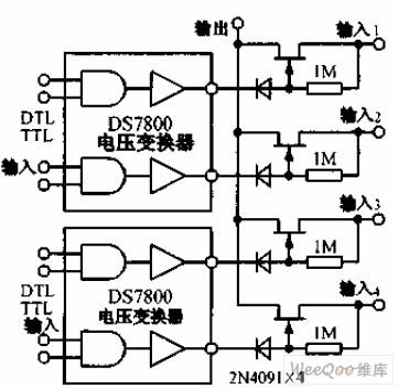
Four-channel switch circuitis shown as the chart, 2N4091 Junction FET power gives each group less than 30Ω on-resistance and a small turn-off leakage current. DS7800 voltage converter provides 10 ~ 20V gate drive voltage to junction field effect transistor, and it is compatible with DTL and TTL circuits. (View)
View full Circuit Diagram | Comments | Reading(1192)
Optocoupler switch circuit diagram
Published:2011/9/15 2:12:00 Author:Rebekka | Keyword: Optocoupler switch
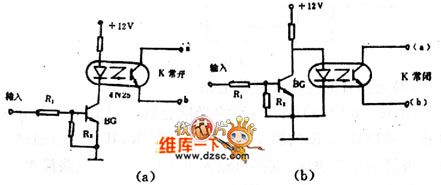
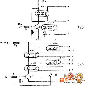
Figure 1 (b) shows off mode of the circuit. As no signal input, BG is stopped. When a signal is input, BG is conducted, due to BG's collector junction drops below 0.3V, which is much smaller than the light-emitting diode forward voltage, the light-emitting diode does not emit light without current flowing, then the resistance of a, b is large. It is equivalent to switch off . It is normally closed type. Visible, a, b ends are not limited by high or low potential in the circuit, but in theapplicationsof the circuit, we should make abe positive, b endbe negative, and U & ab> 3V, at the same time, Uab should be less than the BVceo of optical transistor.
(View)
View full Circuit Diagram | Comments | Reading(1328)
Switch off isolation circuit diagram
Published:2011/9/14 23:48:00 Author:Sophia | Keyword: Switch off, Isolation
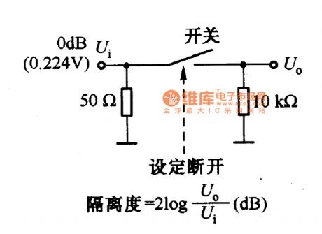
Conversion signal switches include mechanical switches, relays, analog switches. The frequency of the signal must be paid attention to when choosing these switches, not only the signal frequency through the switch need to be paid attention to when the switch is turned on, but also the signal via the switch leakage frequency need to be paid attention to when the switch is off, that is the isolation when switch is off. Figure is a the measurement circuit of the isolation when variety of small-signal switches are off. When frequency is 1MHZ, for mechanical switches and analog switches, the isolation is about 30dB, for the relay, it is about 25dB. Due to the impact of the switch construction and distributed capacitance within the switch, the isolation will become low. Therefore, the circuit construction can be considered to improved. high-frequency signal dedicated switch with enough isolation can be adopted. (View)
View full Circuit Diagram | Comments | Reading(1167)
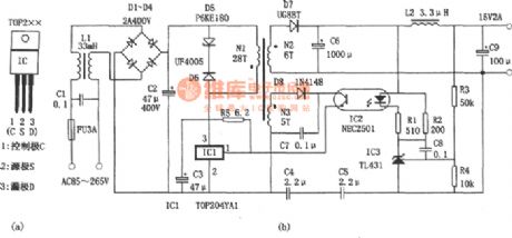
Switch Power Made With Three-terminal PWM Switching Power Supply IC
Published:2011/9/6 6:44:00 Author:Felicity | Keyword: Switch Power, Three-terminal PWM, Switching Power Supply IC
View full Circuit Diagram | Comments | Reading(5038)
Low-power Miniature Switching Power Supply Made With WS157 Or WS106
Published:2011/9/6 6:48:00 Author:Felicity | Keyword: Low-power, Miniature, Switching Power Supply

View full Circuit Diagram | Comments | Reading(1197)
| Pages:1/15 123456789101112131415 |
Circuit Categories
power supply circuit
Amplifier Circuit
Basic Circuit
LED and Light Circuit
Sensor Circuit
Signal Processing
Electrical Equipment Circuit
Control Circuit
Remote Control Circuit
A/D-D/A Converter Circuit
Audio Circuit
Measuring and Test Circuit
Communication Circuit
Computer-Related Circuit
555 Circuit
Automotive Circuit
Repairing Circuit