
LED and Light Circuit
Index 8
DRIVING MANY LEDS Circuit
Published:2013/3/4 21:47:00 Author:Ecco | Keyword: DRIVING MANY LEDS
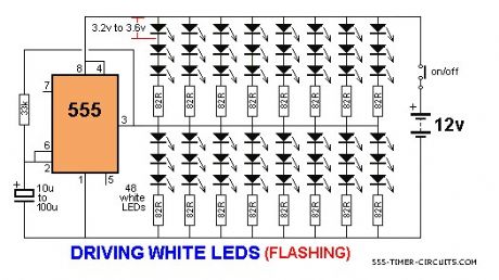
The 555 is capable of sinking and sourcing up to 200mA, but it gets very hot when doing this on a 12v supply. The following circuit shows the maximum number of white LEDs that can be realistically driven from a 555 and we have limited the total current to about 130mA as each LED is designed to pass about 17mA to 22mA maximum. A white LED drops a characteristic 3.2v to 3.6v and this means only 3 LEDs can be placed in series.
(View)
View full Circuit Diagram | Comments | Reading(2387)
DRIVING A BI-COLOUR LED Circuit
Published:2013/3/4 21:43:00 Author:Ecco | Keyword: DRIVING A BI-COLOUR LED
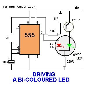
Some 3-leaded LEDs produce red and green. This circuit alternatelyflashes a red/green bi-coloured LED: (View)
View full Circuit Diagram | Comments | Reading(1699)
BI-POLAR LED DRIVER Circuit
Published:2013/3/4 21:30:00 Author:Ecco | Keyword: BI-POLAR LED DRIVER

Some 2-leaded LEDs produce red and green. These are called Bi-polar LEDs. This circuit alternatelyflashes a red/green bi-polar LED:
(View)
View full Circuit Diagram | Comments | Reading(1531)
3x3x3 LED Cube Circuit
Published:2013/3/4 21:21:00 Author:Ecco | Keyword: 3x3x3, LED Cube
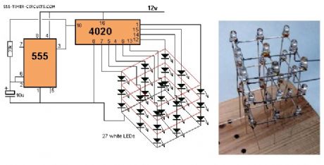
This circuit drives a 3x3x3 cube consisting of 27 white LEDs. The 4020 IC is a 14 stage binary counter and we have used 9 outputs. Each output drives 3 white LEDs in series and we have omitted a dropper resistor as the chip can only deliver a maximum of 15mA per output. The 4020 produces 512 different patterns before the sequence repeats and you have to build the project to see the effects it produces on the 3D cube.
(View)
View full Circuit Diagram | Comments | Reading(5334)
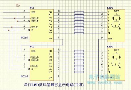
LED- serial LED digital tube static display circuit (common anode )
Published:2013/3/1 2:43:00 Author:Ecco | Keyword: LED, serial , LED digital tube, static display, common anode
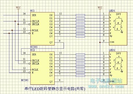
LED- serial LED digital tube static display circuit (common anode ) is shown as figure.
(View)
View full Circuit Diagram | Comments | Reading(1381)
LED - serial LED digital tube static display circuit ( common cathode )
Published:2013/3/1 2:42:00 Author:Ecco | Keyword: LED , serial, LED digital tube , static display , common cathode
LED - serial LED digital tube static display circuit ( common cathode ) is shown as figure.
(View)
View full Circuit Diagram | Comments | Reading(1337)
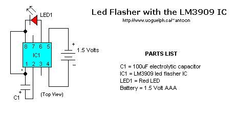
Basic LM3909 Led Flasher
Published:2013/2/27 20:26:00 Author:muriel | Keyword: Basic, LM3909, Led Flasher
View full Circuit Diagram | Comments | Reading(1534)
Automatic Emergency Light
Published:2013/2/24 21:17:00 Author:muriel | Keyword: Automatic Emergency Light
View full Circuit Diagram | Comments | Reading(1899)
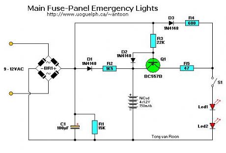
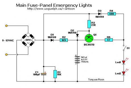
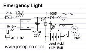
Main Fuse-Panel Emergency Light
Published:2013/2/24 21:16:00 Author:muriel | Keyword: Main , Fuse-Panel, Emergency Light
View full Circuit Diagram | Comments | Reading(1476)
Incandescent Lamp Flasher
Published:2013/2/24 21:00:00 Author:muriel | Keyword: Incandescent Lamp Flasher
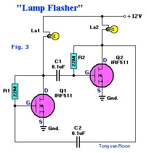
Incandescent Lamp Flasher using two IRF511 HexFets which are configured as a simple astable multivibrator to alternately switch the two lamps, La1 and La2, on and off. The R & C values given set the flash rate to about 1/3 Hz. By varying either the resistor or capacitor values almost any flash rate can be obtainded. Increase either C1 and C2, or R1 and R2, and the flash rate slows. Decrease them and the rate increases.Unlike most semiconductor devices, the power MosFet can be paralleled, without special current-sharing components, to control larger load currents. That can be an important feature when the device is used to turn on incandescent lamps, because the lamp's cold resistance is much lower than the normal operating resistance.A typical #1815 12 to 14-volt lamp measures 6 ohms cold. When 12 volts is applied, the initial current drawn is 2 amps. The same lamp, when operating at 12 volts, requires only about 200mA. The hot resistance figures out to be ten times its cold resistance, or 60 ohms. That tidbit should be considered when picking any semiconductor device to control an incandescent lamp. (View)
View full Circuit Diagram | Comments | Reading(2490)
Laser diode driver circuit with double broadband transconductance operational amplifier OPA2662
Published:2013/2/20 1:00:00 Author:Ecco | Keyword: Laser diode driver , double broadband, transconductance , operational amplifier
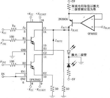
The circuit has a pair of laser -emitting diodes and laser receiver diodes, constituting the reflection laser transmitter and receiver circuits, the figure mainly shows a laser emitting driving circuit.
(View)
View full Circuit Diagram | Comments | Reading(2920)
main fuse-panel emergency lights
Published:2013/2/19 20:12:00 Author:muriel | Keyword: main fuse-panel, emergency lights
View full Circuit Diagram | Comments | Reading(1464)
Emergency Lights 2
Published:2013/2/19 20:10:00 Author:muriel | Keyword: Emergency Lights
View full Circuit Diagram | Comments | Reading(1106)
Emergency Lights 1
Published:2013/2/19 20:10:00 Author:muriel | Keyword: Emergency Lights
View full Circuit Diagram | Comments | Reading(1125)
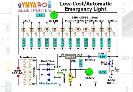
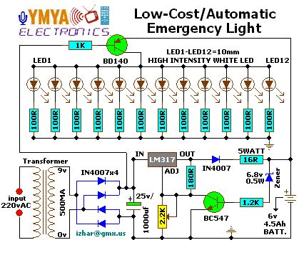
Low cost / Automatic Emergency Light
Published:2013/2/19 20:09:00 Author:muriel | Keyword: Low cost, Automatic , Emergency Light
View full Circuit Diagram | Comments | Reading(1202)
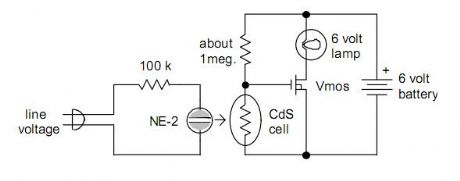
Backup Lamp
Published:2013/2/19 20:05:00 Author:muriel | Keyword: Backup Lamp
View full Circuit Diagram | Comments | Reading(945)
Light control energy-saving lamp (1) circuit
Published:2013/2/17 20:42:00 Author:Ecco | Keyword: Light control, energy-saving lamp
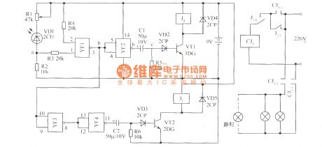
The working principle of the circuit is shown as figure, it is composed of the photoelectric conversion part, NAND gate, differential circuit and control circuit. When there is light, the photosensitive diode VD1 gets conduction, the potential of point A reaches the NAND gate YF1 door level, the output terminal of point b shows low potential, YF2 outputs the high potential, C1 and R5 form a differential circuit which outputs positive spikes at the point C, so BG1 gets conduction, J1 is instantaneously pulled ( then release ). Normally closed contact J1-1 is disconnected, CJ1 loses power and releases, the self-protection contact CJ1-1 disconnects, then the light is off.
(View)
View full Circuit Diagram | Comments | Reading(1346)
SPI Interface Big 7-Seg LED
Published:2013/1/30 21:12:00 Author:muriel | Keyword: SPI Interface, Big, 7-Seg LED
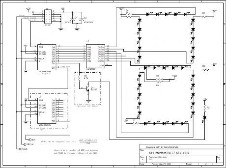
View full Circuit Diagram | Comments | Reading(1581)
Interfacing Alphanumeric LCD
Published:2013/1/30 21:07:00 Author:muriel | Keyword: Interfacing Alphanumeric LCD
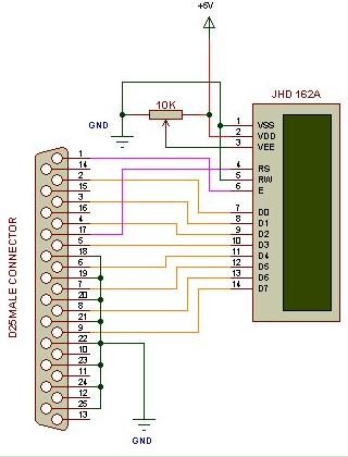
View full Circuit Diagram | Comments | Reading(1345)
Sine wave display on Nokia 3310 LCD
Published:2013/1/29 1:41:00 Author:muriel | Keyword: Sine wave display, Nokia 3310 , LCD
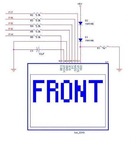
View full Circuit Diagram | Comments | Reading(4895)
| Pages:8/72 1234567891011121314151617181920Under 20 |
Circuit Categories
power supply circuit
Amplifier Circuit
Basic Circuit
LED and Light Circuit
Sensor Circuit
Signal Processing
Electrical Equipment Circuit
Control Circuit
Remote Control Circuit
A/D-D/A Converter Circuit
Audio Circuit
Measuring and Test Circuit
Communication Circuit
Computer-Related Circuit
555 Circuit
Automotive Circuit
Repairing Circuit