
LED and Light Circuit
Index 6
Modified LED Night Light 2
Published:2013/5/7 21:56:00 Author:muriel | Keyword: Modified LED Night Light

View full Circuit Diagram | Comments | Reading(1785)
SOUND TRIGGERED FLASH
Published:2013/5/7 21:39:00 Author:muriel | Keyword: SOUND TRIGGERED FLASH
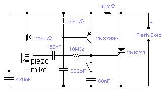
If you wish to take a picture of a fleeting event which generates a sound, you can do it with this sound activated trigger. It does not require any power supply: it feeds on the high voltage available on the flash trigger terminal. Any economic ceramic microphone is suitable for the purpose. The 68nF capacitor introduces a small delay in the operation of the flash and may help in getting the picture in exactly the right moment although you should expect to take several shots for best results. With this circuit you will be able to catch a cork leaving the champagne bottle or the moment a balloon is punctured. The whole circuit could be assembled in the mike housing making a very compact device. (View)
View full Circuit Diagram | Comments | Reading(0)
POWER FLASHER 2
Published:2013/5/7 21:33:00 Author:muriel | Keyword: POWER FLASHER
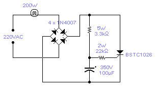
There is no need to resort to complex circuitry if what you are looking for is a simple power flasher. The light will flash at around 1Hz with a 100W bulb at a duty cycle of 50%. The max. load that can be driven with this circuit is 200W and if you wish to have a different frequency you have to change the value of the capacitor. Operation at 110VAC has not been tested although I expect it to work provided the resistors are set at about half the stated value. The SCR is manufactured by Siemens but any other equivalent semiconductor, with standard gate sensitivity, should work fine. WARNING! - This circuit is directly connected to the mains and proper safety precautions should be taken. A more modern design would use a sensitive gate SCR, other low power resistors and a 10μF, 250V electrolytic capacitor. (View)
View full Circuit Diagram | Comments | Reading(1685)
MULTIPLE LED FLASHER
Published:2013/5/7 21:28:00 Author:muriel | Keyword: MULTIPLE LED FLASHER
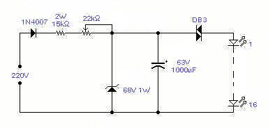
This circuit will flash a string of LED's, typically 16, with direct connection to the mains and with a period adjustable between 1 and 4 seconds depending on the setting of the 22K/1W pot. Operation at 110V should also be possible but has not been tested. It can be used as a Christmas Tree decoration, entertainment in general or to flash a symbol made out of LED's - WARNING - this circuit is implemented at your own riisk! It operates directly out of the mains and proper precautions must be taken. (View)
View full Circuit Diagram | Comments | Reading(0)
SINGLE LED FLASHER
Published:2013/5/7 21:16:00 Author:muriel | Keyword: SINGLE LED FLASHER
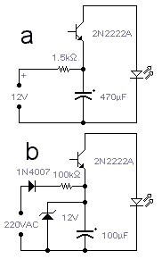
Flashing a LED should not require a complex circuit. A reverse biased transistor does the job in a nice way. Circuit a flashes the LED twice a second: changing the capacitor and/or the resistor will change the frequency, also the supply voltage will influence its frequency of operation. A BC337 can be used instead of the 2N2222A; in this case the supply voltage can be lowered to 9V. Circuit b gives the same result but it will work directly off the mains, so be careful with the live wire because it can be a hazard if you do not take all necessary precautions. If the mains voltage is 110VAC the resistor should be decreased from 100K to 47K. If a BC337 is used, then the resistor is 390K for a 220V mains and 180K for a 110V mains. The zener is not required for its operation: it is only a safety measure that avoids voltage build up if the LED gets disconnected. When you reconnect it, the current surge will destroy the transistor and the LED. The capacitor could be damaged as well. (View)
View full Circuit Diagram | Comments | Reading(0)
20-bit LED / line conversion circuit with two LM3914
Published:2013/4/3 4:02:00 Author:Ecco | Keyword: 20-bit, LED / line conversion
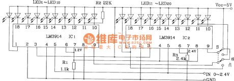
20-bit LED / line conversion circuit with two LM3914 is shown as figure.
(View)
View full Circuit Diagram | Comments | Reading(4718)
LED flowing display electronic clock hardware circuit
Published:2013/4/3 4:03:00 Author:Ecco | Keyword: LED flowing, display, electronic clock, hardware

LED flowing display electronic clock hardware circuit is shown as figure.
(View)
View full Circuit Diagram | Comments | Reading(2921)
The typical application circuit of RY927 multi- segment LED driving linear display
Published:2013/4/3 4:05:00 Author:Ecco | Keyword: typical application, multi- segment, LED driving , linear display
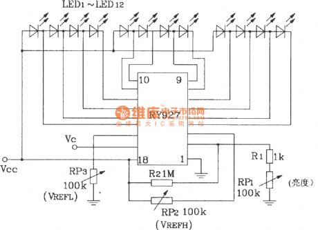
The typical application circuit of RY927 multi- segment LED driving linear display is shown as figure.
(View)
View full Circuit Diagram | Comments | Reading(1982)
The typical wiring of CD4511 drive common cathode LED digital tube
Published:2013/4/3 4:07:00 Author:Ecco | Keyword: typical wiring, drive, common cathode , LED digital tube
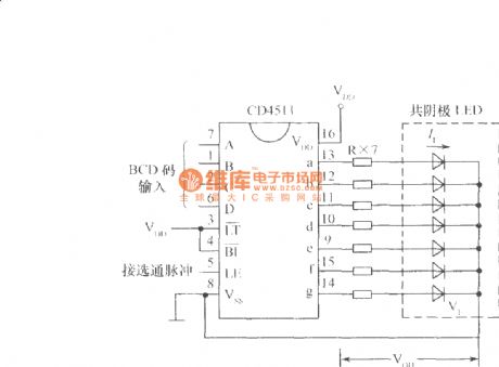
The typical wiring of CD4511 drive common cathode LED digital tube is shown as figure.
(View)
View full Circuit Diagram | Comments | Reading(2335)
Audio-Controlled Incandescent Lamp Light Controller circuit
Published:2013/3/29 4:42:00 Author:Ecco | Keyword: Audio-Controlled , Incandescent Lamp Light, Controller

This is a audio-controlled lamp circuit. This circuit requires low voltage input such as pre-amplifiers, tone control, or general audio line level output. It’s also possible to feed the input with signal from small power amplifier output, or high power amplifier witk low volume level. The characteristic of lamp dimming (incandescent lamp) will look like coming from proportional controller since the switching rate of the TRIAC would be much higher than the lamp dimming response. Here is the schematic diagram of the circuit:
(View)
View full Circuit Diagram | Comments | Reading(1896)
Power Amplifier’s Overload/Clipping Indicator circuit
Published:2013/3/29 4:41:00 Author:Ecco | Keyword: Power Amplifier, Overload/Clipping Indicator
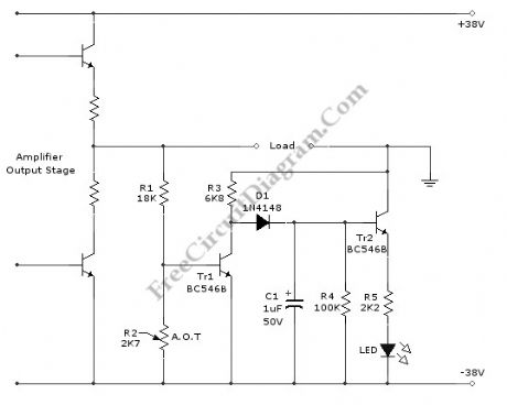
Clipping is a condition where a signal is truncated by insufficient processing. The cause of clipping can be different for various case, but most of them, especially in power amplifier stage, is because the amplifier is forced to serve out-range of power when the input volume is too high. Detecting severely clipped signal is easy by listening, but a soft clipping might be hard to detect. The problem is that some people might notice and some might not. Because our perception of slightly clipped signal might be inconsistent depending on our mood and our mental focus, providing a clipping indication will be very useful for those who responsible in sound performance. This circuit will give visual indicator, the led will light, when the output reach 50Watt level (can be adjusted with R2 pot). Here is the schematic diagram of the circuit.
(View)
View full Circuit Diagram | Comments | Reading(2698)
Color-Shifting LED Show circuit
Published:2013/3/29 4:38:00 Author:Ecco | Keyword: Color-Shifting LED Show
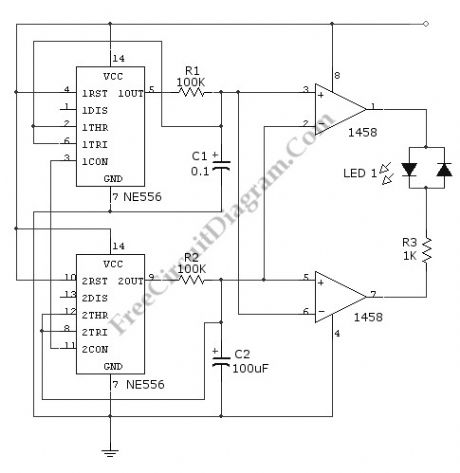
This circuit gives a changing-color LED display, where a LED will emit a dynamic shifting color, from red to green smoothly through yellow. The circuit uses NE556 dual timer, equal to two 555 IC but in only one package. The oscillators is set at different frequencies. The high frequency (upper part) is used to construct a PWM signal, and the lower frequency oscillator is used to control the shifting frequency. What is done by the low frequency oscillator is no more than modulating the duty cycle (active factor) of the PWM.
(View)
View full Circuit Diagram | Comments | Reading(1333)
Sound-Activated Lamp circuit diagram (Relay/Switch)
Published:2013/3/28 3:54:00 Author:Ecco | Keyword: Sound-Activated Lamp , Relay, Switch
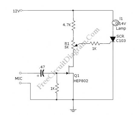
This simple circuit shown int the schematic diagram actives the switch using sound. We can use this circuit for various applications, such as automatic (sound-controlled) disco light or car’s LED light show. The Q1 amplify the audio from mic. The R1 is used to adjust the peak of signal to greater than about 0.7 volts, act as sensitivity adjuster. A certain level, the signal coming from microphone, after amplification by Q1, will trigger the SCR and light lamp I1. If we change the lamp with a relay, then we can get a sound-activated relay/switch, which can be used to control more powerful / high wattage high voltage lamps. If we use a relay, place a 1N4007 diode in parallel with the relay coil to prevent the back-emf from relay coil destroying the SCR. Here is the schematic diagram of the circuit:
(View)
View full Circuit Diagram | Comments | Reading(2637)
Automatic Switch-Off Staircase Light
Published:2013/3/25 3:47:00 Author:Ecco | Keyword: Automatic Switch-Off Staircase, Light
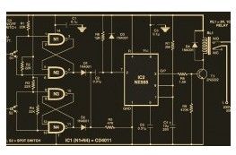
This is the circuit diagram of staircase light with automatic switch off. It based on timer which is can be adjusted with the needs of the time of walking (climbing up and going down) on the staircase.
(View)
View full Circuit Diagram | Comments | Reading(1859)
Light-emitting diode drived by the basic monostable circuit
Published:2013/3/25 2:52:00 Author:Ecco | Keyword: Light-emitting diode , basic monostable circuit
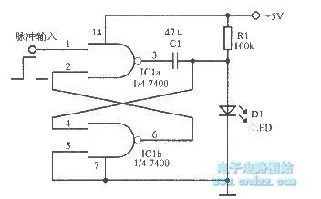
Light-emitting diode drived by the basic monostable circuit is shown as figure.
(View)
View full Circuit Diagram | Comments | Reading(1208)
Ultra Low Power LCD Indicator
Published:2013/3/10 22:59:00 Author:Ecco | Keyword: Ultra Low Power, LCD Indicator
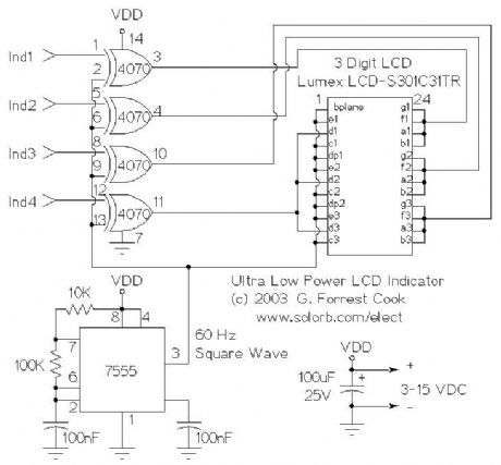
The 7555 IC (CMOS 555 timer) generates a square wave clock signal at approximately 60 hz. This signal is sent to the LCD backplane and the inputs of the four CMOS 4070 XOR gates. If the other input (ind*) of an XOR gate is low, the gate's output is a square wave that is in phase with the clock signal. If the ind* input is high, the gate's output is out of phase with the clock.
Sending a signal to an LCD segment that is in phase with the backplane signal causes the display to stay blank. Sending an out of phase signal to the LCD segment causes an AC waveform to be applied to the segment which turns it black. Multiple segments are wired in parallel to generate the desired display patterns. The LCD segments require a tiny amount of current to operate, the CMOS gates also take very little power, hence the efficient nature of the circuit. It is necessary to tie the unused segments to the LCD backplane, otherwise they may partially turn on.
If more dislay bits are needed, additional XOR gates can be connected in the same manner. Up to 23 XOR gates could be used to drive the entire display, but a microprocessor and driver software would probably be easier to put together. By generating all of the signals with a microprocessor, all of the driving circuitry can be eliminated.
Other logic families could be used to make this circuit, it should work with a standard 555 timer chip and a 74LS86 XOR gate (different pinout), for example.
Some LCDs may not operate at very cold temperatures, an engineer at Lumex said that their components will work from -30C to +75C.
(View)
View full Circuit Diagram | Comments | Reading(1672)
LED Mood Light
Published:2013/3/7 3:05:00 Author:Ecco | Keyword: LED Mood Light

TheoryThe current flows and the LEDs light. There are 4 series strings of LEDs in this circuit, the resistors limit the current through the LEDs and prevent them from burning up. The resistors were adjusted to get approximately 20ma through each string. Different LED colors will have different voltage drops and resulting current flows. These resistor values will work fine at 12V.
Construction
The circuit was mounted in a plastic 35MM photographic slide box with a translucent plastic top (not shown). A piece of perforated board was cut to fit inside of the slide box, the LEDs and resistors were inserted through the holes in the board and the wires were soldered together on the back side of the board. It is recommended that you use a heat sink on the LED leads while you solder them, it is very easy to damage an LED with a soldering iron. A length of speaker wire was used to connect the lamp to the power source. The circuit board was connected to the plastic box with one 6-32 screw and several 6-32 nuts were used as spacers.
(View)
View full Circuit Diagram | Comments | Reading(1327)
13 Color LED Rainbow
Published:2013/3/7 3:04:00 Author:Ecco | Keyword: 13 Color, LED Rainbow
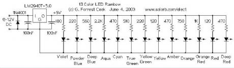
The LM2940T-5.0 low dropout voltage regulator converts the 6-12V DC input power to regulated 5 Volts. It was chosen over a standard 7805 regulator so that the circuit could maintain regulation while operating on a 6V battery. The 1N4001 diode protects the circuit from reverse polarity, if a battery or power supply capable of generating over 1 amp is used, a 1 amp fuse should be installed between the supply and the circuit. The 5 Volts is used to drive each of the LEDs through individual current limiting resistors. The resistor values were determined experimentally for equal brightness. Values are given as examples only, different sources of LEDs will require different resistor values. Resistor selection turns out to be the most difficult part of the circuit's construction. A 100 ohm resistor in series with a 1K pot could be used in place of each resistor if individual brightness adjustments are desired. The table below lists the LED colors and wavelengths.
(View)
View full Circuit Diagram | Comments | Reading(2469)
Remote Solar LED light
Published:2013/3/7 3:03:00 Author:Ecco | Keyword: Remote, Solar LED light
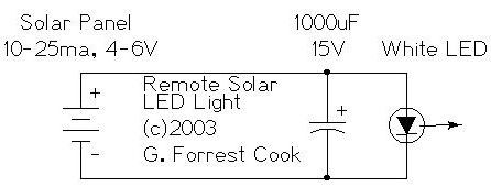
The remote solar powered LED light takes advantage of the current limited nature of solar photovoltaic cells. If light shines on the solar array, current will flow through the circuit. For a typical size of solar cell, there is a maximum current that can be produced. The maximum solar cell current is simply matched to a value of current that the LED can handle. If there is enough light to raise the solar panel's voltage above around 3.7V, the white LED will light up. The LED regulates the maximum voltage across the circuit to around 3.7V.
If the solar panel that you use produces more than 20ma, it may be necessary to insert a series resistor between the LED and the solar panel to prevent the LED from burning out. A 50 ohm 1/4 watt resistor is probably about right for the job, the exact value may need to be optimized according to the solar panel that you use.
This concept could easily be expanded to systems with larger arrays of solar cells and more LEDs. The capacitor is not required, but it will keep the LED from flickering if the panel is briefly blocked, such as when a bird flies by. With 7 solar cells, the LED will only light in fairly bright light, if you use up to 10 solar cells, the circuit will work nicely in overcast skies.
For an interesting modification to this circuit, replace the 1000uF capacitor with a 1 Farad/5.5V Memory Backup Capacitor . An Elna DB-545D105 device was tested on the circuit, after charging up in the sun for a few minutes, the capacitor was able to light the LED for several minutes.
(View)
View full Circuit Diagram | Comments | Reading(1114)
Solar Charged LED Utility Light
Published:2013/3/7 3:02:00 Author:Ecco | Keyword: Solar Charged , LED Utility Light
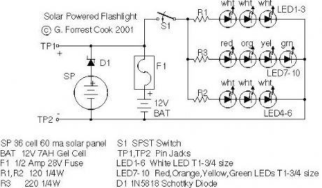
Tired of always spending money on flashlight batteries only to have them fail just when you need them? Try this simple circuit out. The white LEDs are quite bright and produce a tightly focused beam. The LED array can provide enough light to illuminate a small work or reading area at night. The red, orange, yellow and green LEDs broaden the lamp's color spectrum to produce a slighly warmer color temperature. This project would make an excellent science fair project.
The box also doubles as a 12V power source and can run other small loads such as a 12V transistor radio. This project was built with the Simpler is Better approach, the materials are common and many substitutions are possible.
(View)
View full Circuit Diagram | Comments | Reading(1263)
| Pages:6/72 1234567891011121314151617181920Under 20 |
Circuit Categories
power supply circuit
Amplifier Circuit
Basic Circuit
LED and Light Circuit
Sensor Circuit
Signal Processing
Electrical Equipment Circuit
Control Circuit
Remote Control Circuit
A/D-D/A Converter Circuit
Audio Circuit
Measuring and Test Circuit
Communication Circuit
Computer-Related Circuit
555 Circuit
Automotive Circuit
Repairing Circuit