
LED and Light Circuit
Index 19
Mini Led Flashlight with IC
Published:2012/9/27 21:39:00 Author:muriel | Keyword: Mini, Led, Flashlight
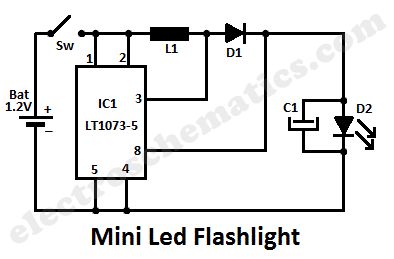
This led lamp circuit can be used as a mini led flashlight. Together with a 1.2 V rechargeable battery, all the components fit into a small enclosure. This is actually a DC to DC converter that convert voltage from a small value to a higher one.The voltage of the battery affects the brightness of a light-emittind diode but if you use this circuit that won’t be a problem anymore. One difference between 1.2 V and 1.5 V is practically not detectable.
The capacitor C1 is used as afterglow when switching off the power supply voltage. If you don’t need this you may disconnect C1. For coil L1 you should use a 82 µH or a 68µH. If you use a lower value for L1 then the circuit will consume more power than really should do.
Although this mini led flashlight kit contains an IC, this circuit is suitable for beginners. This circuit is fast and allows a quick sense of achievement. With a bit of skill to make a case (such as a can or box) is adopted so that this circuit with battery takes place.
Led Flashlight circuit diagram
Components ValuesIC1 = DC-DC converter – LT1073-5L1 = Coil – 82 uHC1 = Capacitor 220 μFD1 = Diode 1N5818D2 = LED / White / Super bright
(View)
View full Circuit Diagram | Comments | Reading(2693)
LED flashing circuit
Published:2012/9/27 21:38:00 Author:muriel | Keyword: LED, flashing circuit
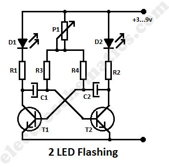
This is a simple led flashing circuit with 2 leds. It illustrates the behavior of transistors and capacitors and if you use an oscilloscope it will be very easy to determine what happens in this astable multivibrator circuit. It’s state is constantly changing and this change affect the flow of current and voltage and the effect will be visible with the two leds.The speed of the led flasher may be adjusted with potentiometer P1. Being an astable multivibrator, the circuit knows no stable state but oscillates continuously between two states back and forth. The two transistors T1 and T2 turn and lock each other by turn. The smaller the capacitor and the smaller the resistance , the faster goes out the appropriate diode, for the benefit of others, who then immediately turns on.
The activation time of T2 is t, a = 0.7 x R1 x C1, the switch-off t off = 0.7 x R2 x C2.
The switch from T1 is t, a = 0.7 x R2 x C2, the off t off = 0.7 x R1 x C1.
The transistors do not necessarily have to be BC 547 B, you may use BC 238 or similar small-signal transistors. It is recommended to always use the equivalent transistors. If one of the transistors is defective, wrong or have a malfunction , so does this to the full functionality of this circuit . An LED lights up and the other only very weakly.
The two led flashing circuit is designed for 9 Volts but it works at even less voltages. In this designed we used red leds but by changing the series resistors R1 and R4 you can also use different colored LEDs.
Two Led flashing circuit diagram
Components valuesR1 - 470 OhmR2 - 470 OhmR3 - 3.9 kOhmR4 – 3.9 kOhmP1 - 50 kOhmC1 – 47 μF / 16VC2 - 47 μF / 16VT1 - BC 547 BT2 - BC 547 BD1 - LED Standard , 5 mm , redD2 - LED Standard , 5 mm , red
(View)
View full Circuit Diagram | Comments | Reading(2876)
Flashing Light Circuit
Published:2012/9/26 21:35:00 Author:muriel | Keyword: Flashing Light
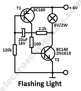
This simple flashing light circuit is powered with 6 volts/0.5A and has a low current consumption when the light bulb is off. The flashing frequency is set by only one capacitor. Transistor T1 may be replaced with BC160 and T2 with BC140.
Simple Flashing Light Circuit Diagram
(View)
View full Circuit Diagram | Comments | Reading(2364)
Mini Emergency Light circuit
Published:2012/9/25 21:47:00 Author:muriel | Keyword: Mini, Emergency Light
This is an LDR based Emergency Lampthat turns on a High watt White LED when there is darkness in the room. It can be used as a simple emergency lamp in the child’s room to avoid the panic situation in the event a sudden power failure.It gives ample light in the room.The circuit is too simple so that it can be enclosed in a small box. A 12 volt miniature battery is used to power the circuit. Two transistors T1 and T2 are used as electronic switches to turn on / off the white LED. When there is sufficient light in the room, LDR conducts so that the base of the PNP transistor T1becomes high and it remains off. T2 also remains off since its base is grounded. In this state, White LED remains off. When the light falling on the LDR decreases, it cease to conduct and T1 forward bias providing base current to T2. It then turns on and White LED switches on.
Mini Emergency Light Circuit Schematic
White LED used in the circuit is 1 watt High bright Luxeon LED. Since 1 watt White LED consumes around 300 milli ampere current, it is better to switch off the lamp after few minutes to conserve battery power. (View)
View full Circuit Diagram | Comments | Reading(2094)
USB Lamp circuit
Published:2012/9/25 21:46:00 Author:muriel | Keyword: USB, Lamp
Here is a simple USB lamp powered from the USB socket of PC. It uses 5mm high bright White LEDs to give ample light to work in the Keyboard if the room light is not sufficient. No PCB is required to make this circuit.The circuit is too simple and can be wired through lead-to-lead soldering. The LEds are connected to current limiting resistors R1 through R4.The cathode of all LEDs are joined together and soldered to the black wire of USB cable. Free leads of all the resistors are joined together and connected to the Red wire of USB cable. You can use a discarded USB cable with Class A type connector. Cut the Green and White wires of the USB cable and use only Red and Black wires. USB socket of PC provides 5 volts so that the LEDs give bright light. LEDs can be fixed in the Key board by drilling 5 mm holes.
USB Lamp Circuit Schematic
USB Cable
Class A USB Connector (View)
View full Circuit Diagram | Comments | Reading(1734)
LED Night Lamp circuit
Published:2012/9/25 21:44:00 Author:muriel | Keyword: LED, Night, Lamp
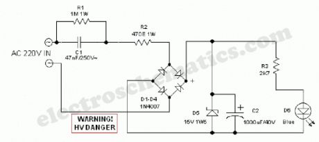
The design of the LED night lamp circuit (bedroom light) is similar to that of many commercially available products. However, the light circuit does not use any kind of bulky and noisy stepdown transformers, but a capacitive potential divider is inserted in a simple manner to provide a constant current for driving the light source. Here a high-efficiency, low current blue LED is used as the light source. The design is safe, simple and stable!
Night Lamp Circuit Schematic
When input power (AC 220V) is available, capacitor C2 is charged through C1 and R2 and bridge rectifier assembly D1-D4. Zener diode D5 limits the voltage across C2 to a safe value of near 15V. This low voltage dc supply is then fed to the LED (D6) via current limiting resistor R3. When the input supply is removed, LED stays on unchanged for a short time and then diminishes gradually. No instant darkness when the supply is switched off!
After construction, enclose the circuit in a small plastic box. Drill a 5mm hole in the centre of the enclosure and fit the LED in a suitable LED holder in the 5mm hole. Finally fit a supply input socket and, optionally an on/off switch at the rear/side of the enclosure.
WARNING! Great care should be taken when working with this led night lamp circuit since it is connected directly to the fatal mains supply. (View)
View full Circuit Diagram | Comments | Reading(2780)
Flashing LED circuit with LDR
Published:2012/9/25 21:40:00 Author:muriel | Keyword: Flashing, LED circuit, LDR
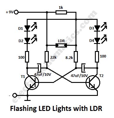
In this flashing led lights circuit, the LDR or photoresistor is connected in such way that when the light intensity varies it will influence the flashing frequency and the brightness of the LEDs. T1, T2 = BC547, BC548, BC549 (any NPN transistor).
You can arrange the LEDs D1 to D4 in cross in order to obtain interesting effecs. The whole flashing led circuit is powered from a 9 volt battery and can be built small enough so it will fit in a matchbox.
Schematic of Flashing Lights with photoresistor
(View)
View full Circuit Diagram | Comments | Reading(2877)
Portable Solar Lantern
Published:2012/9/25 21:24:00 Author:muriel | Keyword: Portable,Solar,Lantern
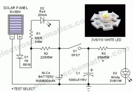

This portable solar lantern circuit uses 6 volt/5 watt solar panels are now widely available. With the help of such a photo-voltaic panel we can construct an economical, simple but efficient and truly portable solar lantern unit. Next important component required is a high power (1watt) white LED module. When solar panel is well exposed to sunlight, about 9 volt dc available from the panel can be used to recharge a 4.8 volt /600 mAh rated Ni-Cd batterypack. Here red LED (D2) functions as a charging process indicator with the help of resistor R1. Resistor R2 regulates the charging current flow to near 150mA.Assuming a 4-5 hour sunlit day, the solar panel (150mA current set by the charge controller resistor R2) will pump about 600 – 750 mAh into the battery pack. When power switch S1 is turned on, dc supply from the Ni-Cd battery pack is extended to the white LED (D3). Resistor R3 determines the LED current. Capacitor C1 works as a buffer.
Note: After construction, slightly change the values of R1,R2 and R3 up/down by trial&error method, if necessary.
Solar Lantern Circuit Schematic
(View)
View full Circuit Diagram | Comments | Reading(1669)
LED Chaser circuits
Published:2012/9/25 1:00:00 Author:muriel | Keyword: LED, Chaser
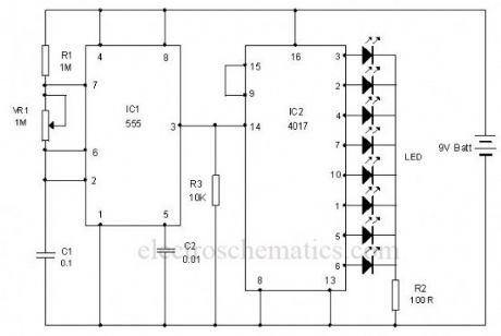
This is the circuit of a simple LED chaser. The LEDs lights one by one for a period of 1second and the cycle repeats giving the running light appearance. The circuit uses two ICs (one is 555) to drive the LEDs.IC1 (NE555) is the popular timer IC wired in the Astable Multivibrator mode. Resistors R1, VR1 and capacitor C1 act as the timing components and the output pulses are available from the output pin 3 of IC1. These pulses are given to the input pin 14 of the Johnson decade counter IC CD4017. Out of the 10 outputs of IC2, eight outputs are used to drive the LEDs. The ninth output pin 9 is connected to the reset pin 15 to stop the counting. So that the cycle repeats. With the value of C1, each LED remains on for 1second. When one LED turns off, the second on turns on. This cycle repeats giving the running light appearance. Resistor R3 keeps the input pin 14 of IC2 low after each pulse.VR1 adjusts the speed of LED chasing.
LED Chaser Circuit
(View)
View full Circuit Diagram | Comments | Reading(2774)
LED Chaser circuit
Published:2012/9/25 1:00:00 Author:muriel | Keyword: LED,Chaser

This is the circuit of a simple LED chaser. The LEDs lights one by one for a period of 1second and the cycle repeats giving the running light appearance. The circuit uses two ICs (one is 555) to drive the LEDs.IC1 (NE555) is the popular timer IC wired in the Astable Multivibrator mode. Resistors R1, VR1 and capacitor C1 act as the timing components and the output pulses are available from the output pin 3 of IC1. These pulses are given to the input pin 14 of the Johnson decade counter IC CD4017. Out of the 10 outputs of IC2, eight outputs are used to drive the LEDs. The ninth output pin 9 is connected to the reset pin 15 to stop the counting. So that the cycle repeats. With the value of C1, each LED remains on for 1second. When one LED turns off, the second on turns on. This cycle repeats giving the running light appearance. Resistor R3 keeps the input pin 14 of IC2 low after each pulse.VR1 adjusts the speed of LED chasing.
LED Chaser Circuit
(View)
View full Circuit Diagram | Comments | Reading(2708)
Light Controlled Bistable circuit
Published:2012/9/25 0:57:00 Author:muriel | Keyword: Bistable,Controlled,Light
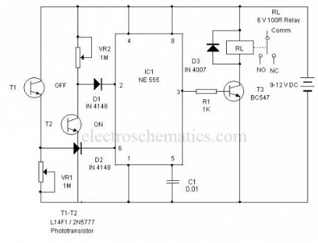
This circuit can control AC loads such as Lights, Fans etc through the remote handset of TV. The circuit uses the popular timer IC 555 in the Bistable mode.In the Bistable mode output IC555 keeps two states, either low or high. When a negative pulse is applied to the trigger pin 2 of 555, the output turns high and remains as such in the latched state. If a positive pulse is applied to the Threshold pin 6, its output turns low and remains as such. This property is used to control the AC load.
Light Controlled Bistable Schematics
The negative and positive pulses are given to the trigger and threshold pins of 555 through the light activated phototransistors T1 and T2. The collector of T2 is connected to the trigger pin 2 through diode D1. Similarly the emitter of T2 is connected to the threshold pin 6 through diode D2. When the IR beam of remote is focused momentarily to T2, it conducts and takes the trigger pin 2 to ground potential. This triggers IC1 and its output goes high. T3 then conducts and relay turns on. Load connected to the NO contacts of the relay gets electrical continuity and turns on. When the IR beam is focused on T1, Current passes from its emitter into the threshold pin6 and the output of IC1 turns low and the relay de-energize to switch off the load.
Setting: Keep both Photo transistors in Black tubes to avoid ambient light falling on them. This is necessary for the proper functioning of the circuit. Since the remote emits pulsating IR beam, use only the On/Off button to give continuous IR beam. Press the button only once to activate the circuit. Keep the photo transistors facing two directions so that IR rays will not interfere them. The circuit can also be activated through torch and Laser pointer. Adjust VR1 and VR2 to set the sensitivity of Phototransistors at the particular light level in the room. That is, the circuit should not be activated in day light. (View)
View full Circuit Diagram | Comments | Reading(1791)
LED workbench lighting
Published:2012/9/25 0:54:00 Author:muriel | Keyword: LED,workbench,lighting

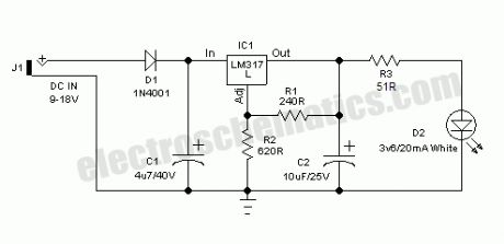
Here is a very useful workbench lighting unit for electronics hobbyists. The portable inspection lamp circuit consists of an on-board voltage regulator and a high-bright 5mm white LED. Any 9 to 18 volt dc rated ac mains adaptor, capable to source about 100 mA of output current can be used to power this portable inspection lamp.After contruction the led workbench light circuit should be enclosed in a suitable plastic bottle cap as illustrated here. The miniature lens shown is an optional component. In the prototype, plastic made lens lifted from a discarded torch was used!The adjustable 3-pin voltage regulator IC1 (LM317L) in TO-92 pack, is here tuned to supply an output of near 4.5 volt dc. This supply is directly fed to the white LED (D2) through the current limiter resistor R3 (51 Ohm). Diode D1 (1N4001) works as an input polarity protection guard and two small electrolytic capacitors (C1 and C2) connected at the input and output pins of IC1 improves the overall stability of the regulator circuit. Use a standard RCA or EP socket as the input terminal J1.
LED workbench lighting lamp circuit schematic
(View)
View full Circuit Diagram | Comments | Reading(2024)
Automatic emergency light circuits
Published:2012/9/25 0:54:00 Author:muriel | Keyword: Automatic,emergency light
This low cost automatic emergency lighting circuit turns on a lamp during power failures. It is powered by a NiCad battery that is being charged by the main power line when there is no blackout. The circuit design is very simple and can be made by almost anyone. How does the automatic emergency light works
The voltage from the step down transformer is rectified by diode D1 and filtered by C1. The NiCad battery gets charged with about 100 mA via the diode D2 and resistor R1. The battery must have a capacity of at least 2 Ah to tolerate the charging rate.
When the main power supply fails during a blackout, the charging current is interrupted and a current flows from the base of T1 via resistor R2 which triggers the transistor to conduct and the two emergency lamps light up. When the main power returns, the charging current flows again through D2 and the transistor turns the lamps off.
The “TEST” button S1 is used to check the function of the circuit. If the secondary coil of the transformer delivers a higher voltage level, replace R1 with a higher value resistor to avoid exceeding the maximum charging current allowed for the NiCad battery being used.
Emergency light parts220V to 4.5V / 2A TransformerD1 = 1N4004D2 = 1N4001R1 = 33Ω/1WR2 = 470ΩC1 = 470µF/16VT1 = 2SB242La1, La2 = 2.5V bulbsBattery = 2.5V / 2Ah Nicad
Automatic Emergency Lighting Circuit Diagram
(View)
View full Circuit Diagram | Comments | Reading(2099)
Jumbo Flashing LED Lights
Published:2012/9/25 0:52:00 Author:muriel | Keyword: Flashing,LED Lights
This is a flashing led lights circuit powered from a 12V DC power supply that uses the well known 555 IC. Flashing lights have many and varied applications in life. They are used as warning lights on highways to increase road safety, as beacons on towers, as advertising signs on shop windows,and so on.
Mechanically operated flashers have a short life and many of them generate lot of electrical interference by sparking at the switch contacts. On the other hand, neon lights are power hungry types.
How does the flashing led lights works
12VDC powered true solid-state circuit of the Jumbo LED flasher presented here is wired around LM555(IC1). This IC workes as a low frequency oscillator, drives 5 to 10mm sized, 4 to 40 Red LEDs through a medium power npn transistor 2N2222 (T1).
LM555 IC is configured in a different style by adding a potential divider at its control terminal (Pin 5) to shift the comparator reference levels either higher or lower than the nominal 1/3, 2/3 levels. User can change the LED flashing rate by adjusting the P1.
LED Flashing Lights Circuit Schematic
(View)
View full Circuit Diagram | Comments | Reading(2876)
Automatic Lawn Light with LDR
Published:2012/9/24 22:26:00 Author:muriel | Keyword: Automatic,Lawn Light,LDR
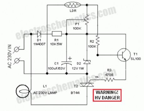
Circuit of a compact and true solid-state automatic lawn light is described here.The circuit can be used to switch on incandescent garden light bulbs at desk and switch off them at dawn. A 10 mm encapsulated light dependent resistor (LDR) here works as the twilight detector.The whole circuit can be housed in a very small plastic cabinet.For powering the circuit AC 230V household supply is needed. With a little skill and patience, you can easily modify this circuit to drive a number of white LED strings, instead of the incandescent bulb load at the output.When ambient light is normal, transistor T1 is reverse biased by the low resistance of LDR. Multi-turn palstic trimpot P1 sets the detection sensitivity. If ambient light dims, transistor T1 turns on to drive the triac T2. Now the lamp load at the output of T2 energises.When the ambient light level restores, circuit returns to its idle state and light(s) switched off by the circuit.Working voltage for the circuit is derived directly from the AC supply input through components D1, R1, D2 and C1. This obviates the requirement of a bulky and noisy step-down transformer.
If you wish to operate the light bulb(s) on a little reduced power,just replace the triac T2 with a suitable silicon controlled rectifier (SCR). This may give a long life to the incandescent load. Finally, the LDR should not be mounted to receive direct sunlight. It may be mounted at the top of the enclosure, pointing to the sky say southwards.
LDR Lawn Lights Circuit Schematic
(View)
View full Circuit Diagram | Comments | Reading(4163)
X’Mas LED Decoration circuit
Published:2012/9/24 22:25:00 Author:muriel | Keyword: X’Mas,LED Decoration
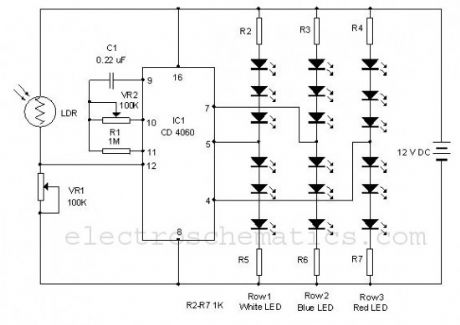
Using this simple circuit, you can make an 18 LED flasher to decorate the X’Mas Tree. The White, Blue and Red LEDs flash at different rates to give a colorful display. It is a light sensitive circuit so that it will turn on in the evening automatically and stays on till morning.The circuit uses the popular Binary counter IC CD 4060 to flash the LEDs at different rates. Components C1, VR2 and R1 form the oscillator and the output pins 7, 5 and 4 become high / low sequentially. When one output turns high, a set of 3 LEDs turn on and when the same output turns off, the second set turns on. This sequence is similar in the other two sets of LEDs also but with different timings. The speed of the Flashing can be controlled through VR2.
Christmas Light Decoration Circuit Schematic
(View)
View full Circuit Diagram | Comments | Reading(3177)
Automobile White LED Light
Published:2012/9/24 22:23:00 Author:muriel | Keyword: Automobile,White,LED Light
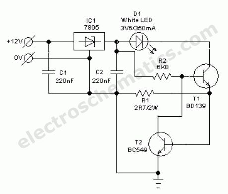
Without any dedicated buck converter/white LED driver IC, you can safely drive many standard Hi-efficieny white LED modules using the battery power available in automobiles. Here is a safe and simple white LED driver designed for 12V automobiles.In the Automobile White LED Light circuit, fixed voltage regulator IC1 (7805) provides a steady voltage of 5V across C2. Resistors R1 limits the current flow through the white LED D1 (3v6/350mA) with the help of transistor T1 (and T2), ie components R1, T1 (and T2) provide a constant current to D1. Use a good heat sink for T1. This LED unit gives a constant light output for input voltages ranging from 8 to 18 volts!
Auto White LED Circuit Schematic
(View)
View full Circuit Diagram | Comments | Reading(2443)
Low Cost LED Blinker circuit
Published:2012/9/24 22:21:00 Author:muriel | Keyword: LED, Blinker
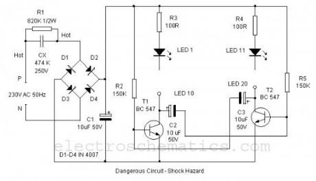
Here is a simple LED Alternate flasher for decoration purpose. The 20 High bright LEDs flashes alternately giving a brilliant colour display. The circuit is low cost and derives DC directly from AC without using a step down transformer. The design is too simple so that the circuit can be assembled on a small piece of common PCB.Power to the circuit is derived from 230 Volt AC through AC capacitor CX which is used to step down 230 volt AC to low volt AC. 474 K 250 Volt AC capacitor gives around 20 volts AC and 40 mA current. This low volt AC is rectified through the Bridge rectifier D1 through D4 and filtered by C1.
The LED driver is an Astable multivibrator using two NPN transistors T1 and T2.The circuit works on the principle of charging and discharging of capacitors C2 and C3. Current from the positive rail flows through first set of LEDs 1- 10 to the collector of T1 through resistor R3. Resistor R3 limits current through the LEDs to protect them.
The current through R3 and LEDs charges capacitor C2. It then discharges through the base of T2 and resistor R5. This gives base current to T2 and it conducts. As a result second set of LEDs 11-20 lights. As the Capacitor C2 discharges completely, T2 turns off and LEDs 11-20 also turns off. The same thing happens in the other side also. This gives alternate flashing of LEDs. Thus the flashing effect is produced through the switching of T1 and T2 by the charge from capacitors.
Low cost LED Blinker circuit diagram
(View)
View full Circuit Diagram | Comments | Reading(2186)
Electronic Doorbell Light Schematic
Published:2012/9/24 4:23:00 Author:muriel | Keyword: Electronic, Doorbell, Light

This 6V battery operated doorbell light circuit can be connected in parallel with any existing AC230V doorbell. When anyone push the doorbell switch, the bell sounds as usual and ac mains supply available across the doorbell is routed to the input of this circuit through an opto-coupler(IC1).Conduction of IC1 triggers a monostable, wired around the good old 555 timer (IC2). As a result the high-bright white LED (D2) at the output of IC2 is switched on for a short time. This circuit is highly useful at night/midnight as it gives sufficient indoor light to help you locate switches for room lamp/porch light, etc. On/Off duration of the LED light can be increased/decreased by increasing/decreasing the value of C2.The electronic doorbell light circuit is fully safe because it is perfectly isolated from the fatal ac mains supply by IC1. However, keep to avoid accidental contacts with the front end of the circuit, which is directly connected to the ac supply. Use of a good and convenient ABS enclosure is recommended for this doorbell light unit.
Electronic Doorbell Light Circuit Schematic
?
12 Responses to “Electronic Doorbell Light Schematic”
(View)
View full Circuit Diagram | Comments | Reading(2008)
Light Dependent Resistor PC Desk Lamp
Published:2012/9/24 4:19:00 Author:muriel | Keyword: Light, Dependent Resistor, PC, Desk Lamp
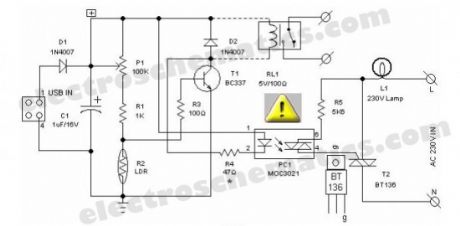
Most of the PC desk lamps available in the market light up whenever there is an input power. These don’t take into account whether there is a real need for the light or not. Here is an intelligent PC desk lamp circuit that overcome the problem.It senses the light level in the room to determine the actual need for light and lights up only if required. It is designed to work with the PC and remains on only when the PC in the table is in working state. It uses MOC3021.Front end of the circuit is powered by the 5volt dc supply available from the usb port of the PC. When circuit is powered, the light sensor LDR (R2) resistance is low if there is sufficient light and thus most of the base current of transistor T1 finds an alternative easy path via LDR and T1 remains cutoff. While during dakness, the LDR behaves almost as an open circuit, and the current through sensitivity control preset pot (P1) and assosiated resistors (R1,R3) flows into the transistor’s base. As a consequence, T1 conducts to energise the opto-triac PC1. Next, the lamp driver triac T2 is fired through the opto-triac PC1 and switch on the power supply to the incandescent lamp.The circuit can be constructed on a medium size PCB. After construction, enclose the finished circuit in a well insulated plastic cabinet. Then drill holes for mounting the ‘B’ type USB input socket, power switching termianls and the LDR etc. This circuit is meant for use in conjuction with Personal Computers to switch on an associated light sensitive table lamp/similar load. An optional electro magnetic relay can also be wired at the output of the circuit to switch heavy electrical load(s). For interconnection between PC and the control circuit, use a standard USB cable with an ‘A’ type connector on one end and a ‘B’ type connector at the other end.
LDR USB Desktop Lamp Circuit Schematic
Warning! This LED PC Desk Lamp circuit is perfectly isolated from mains. However some parts of the circuit carries dangerously high voltages. So ,while testing,using or repairing take extreme care to avoid the fatal electric shock.?
6 Responses to “Light Dependent Resistor PC Desk Lamp”
(View)
View full Circuit Diagram | Comments | Reading(1700)
| Pages:19/72 1234567891011121314151617181920Under 20 |
Circuit Categories
power supply circuit
Amplifier Circuit
Basic Circuit
LED and Light Circuit
Sensor Circuit
Signal Processing
Electrical Equipment Circuit
Control Circuit
Remote Control Circuit
A/D-D/A Converter Circuit
Audio Circuit
Measuring and Test Circuit
Communication Circuit
Computer-Related Circuit
555 Circuit
Automotive Circuit
Repairing Circuit