
LED and Light Circuit
Index 21
High temperature indicator circuit
Published:2012/9/18 21:35:00 Author:Ecco | Keyword: High temperature, indicator
In some areas there is a need of temperature detectors which help them to detect temperature and indicate them?whether the temperature is low or not.
Below shown circuit is the simple high temperature indicator circuit. It will not show the current temperature but if it exceeds some threshold temperature it will detect and indicate. You can use this circuit anywhere you needed.
The components needed for the circuit are:
3 Resistors
1 Temperature dependent resistor
5v battery
Two 1n4007 diodes
One Op-Amp
One LED
And the circuit working is actually very simple, the Op-amp is connected as Non-inverting comparator. And a bridge circuit is made with the resistors and a Temperature Dependent Resistor. From above circuit R1, R2 and R3 are normal resistors but RT is Temperature Dependent Resistor.
The bridge resistance and RT are selected in such a way that as long as temperature is less than threshold value, the bridge is unbalanced by making Voltage at B more than voltage at A . Hence Vo = -Vsat and LED is reverse biased and remains OFF. When temperature becomes more than threshold then Voltage at B becomes less that Voltage at A hence it drives Vo = +Vsat. Due to this, LED glows and gives high temperature indication.
If you have any doubts about the above circuit, don’t hesitate to comment.
One Response to “High temperature indicator circuit”
(View)
View full Circuit Diagram | Comments | Reading(1260)
Single 1.2V NiMH Cell LEDs Flashlight
Published:2012/9/18 21:35:00 Author:Ecco | Keyword: Single, 1.2V , NiMH Cell, LEDs Flashlight
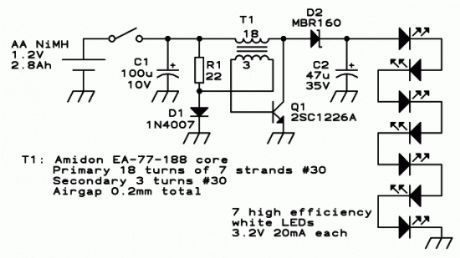
The single cell led flashlight circuit is a self-oscillating boost converter. A typical white LED has its best power-efficiency combination at about 20mA, and needs about 3.3V. This makes for a power of about 66mW per LED. In this circuit are 7 series LEDs so we need a driver circuit that will provide about 23V at 20mA, when fed from a 1.2V NiMH rechargeable cell or from a 1.5V alkaline cell.
When switching it on, R1 and D1 bias the transistor into the linear range, through the feedback winding on T1. That causes a current through the 18 turn winding, and thanks to the positive feedback the transistor is driven into saturation. At this moment there will be a base current defined like this: The 1.2V of the cell, plus the 0.2V induced in the feedback winding, minus the 0.7V base-emitter drop of the transistor, make a total of 0.7V, which applied to the 22 ohm resistor gives about 32mA base current. D1 is not conducting a significant current at this time, because the transistor clamps the base voltage to 0.7V and the 3 turn winding subtracts 0.2V from this, so that we end up with only 0.5V across the diode.
This base current keeps the transistor in saturation until its collector current reaches approximately 1A, while the transformer loads up. At this point the transistor will start getting out of saturation, which makes the feedback voltage drop. This very quickly puts the transistor into blockage. The collector voltage will soar as T1 forces current to keep flowing, until D2 starts conducting and discharges the transformer into C2, by means of a quite narrow pulse. During operation this pulse is about 24V high, so that the feedback winding develops -4V, which results in applying about -3.3V to Q1′s base, enough to switch it off very fast, but not enough to make the base reverse-conduct.
As soon as the transformer has fully discharged into C2, the voltage on it breaks down, and the transistor enters conduction to start a new cycle. The oscillating frequency is 30kHz, and the transformer operates at a peak flux density of 0.1 tesla, far away from saturation, and low enough to have very low loss. C2 has to eat the load pulses that start at about 1A, and has to keep the voltage constant enough to feed the LEDs an almost smooth DC. The value given works well. If anyone wants to build this circuit to run 24 hours a day for 30 years, it would be good to pick a capacitor rated for low ESR and a relatively high ripple current, but for flashlight use a plain standard 47μF, 35V electrolytic capacitor works great.
C1 is not strictly necessary. With a good NiMH cell, the circuit works the same without it, so you can save a few cents here. But with the capacitor in place, the circuit keeps working better when the cell is almost fully discharged and its internal resistance gets higher, so it’s better to include it.
Source: http://ludens.cl/Electron/ledlamp/ledlamp.html
2 Responses to “Single 1.2V NiMH Cell LEDs Flashlight”
(View)
View full Circuit Diagram | Comments | Reading(1947)
Automatic street light circuit
Published:2012/9/18 21:34:00 Author:Ecco | Keyword: Automatic street light

There have been lot of problems in street lights. Major problem in some places is every evening a person has to come and switch ON the street light and it should be again switched off in morning. Yes, this may not be the situation in everywhere but exists in many places.So this problem can be overcome by using a simple circuit. Below shown circuit will be automatically switched ON and OFF during night and morning times respectively.
Automatic light schematic
In above circuit R1 can be used to adjust the sensitivity. And the working of the circuit is very simple. The LDR will have very low resistance during day time so the transistor Q1 will be in OFF condition. And during night time the resistance will be very high so automatically the transistor Q1 will be ON.
The Q1 is PNP transistor and the emitter of Q1 is given to base of Q2. So the Q2 transistor will be ON only if the transistor Q1 is ON. The TRIAC is used in the circuit to make is circuit complete. As the TRIAC will allow voltage to pass from either directions only when there is a certain threshold voltage in gate terminal. And the gate of TRIAC is controlled by transistor Q2.
So totally the lamp will be ON during night time and will be again switched off during day light. To change the sensitivity of the circuit to light adjust R2.
If you have any doubts, do not hesitate to comment below. We will come to you with an appropriate solution.
19 responses to “Automatic street light circuit”
(View)
View full Circuit Diagram | Comments | Reading(1468)
Automatic Light Switch with PhotoTransistor
Published:2012/9/18 21:34:00 Author:Ecco | Keyword: Automatic Light Switch, PhotoTransistor
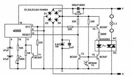
This is an automatic light switch circuit that turns ON a light bulb in absence of light. The IC 4060 works as an oscillator and generates a signal that is applied to the base of T4 transistor. Phototransistor T3 BPW40 is in conduction when light is present and it keeps the T5 transistor’s base at ground potential.When light goes out and it doesn’t reaches the phototransistor, it gets in insulation. T3 reaches positive potential through 22kohm. T4 and T5 both gets in conductance. The oscillator signal reaches the optic coupler and then turns on the lamp.
2 Responses to “Automatic Light Switch with PhotoTransistor”
(View)
View full Circuit Diagram | Comments | Reading(2219)
LED Driver with 555 Timer
Published:2012/9/18 21:31:00 Author:Ecco | Keyword: LED Driver , 555 Timer
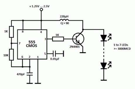
This simple LED driver circuit allows us to drive up to seven LEDs by using a single NiMH (Nickel Metal Hydride) AA cell. The circuit produces voltage pulses at a much higher level than the input supply voltage by pulsing the 220 uH inductor. The inductor must be a high Q (Q>90) power inductor. When the input is 1.25 V and the LEDs are connected, the voltage pulse level will be 23V.The LED driver uses a CMOS 555 timer since it operated with low voltages and can work for about 190 hours when using a single NiMH battery cell rated at 2000 mAh. The 555 timer drives the transistor at 222 kHz rate.
The seven LED groups can be connected paralelly if their forward voltages match. If not, the LED group with the lowest forward voltage value will dim out the other group(s). This parallel connection will not affect the total current drawn from the battery but it will reduce the brightness of the LEDs.
LED Driver Circuit Schematic
When a single 1.25V cell is used, the seven LED group will draw about 8mA from the battery. When the input value increases to 2.5V, the total drawn current will be 20mA.
5 Responses to “LED Driver with 555 Timer”
(View)
View full Circuit Diagram | Comments | Reading(3695)
Automatic Solar Garden Lights with LEDs
Published:2012/9/18 21:24:00 Author:Ecco | Keyword: Automatic , Solar Garden Lights , LEDs
Efficient automatic solar garder lights circuit with minimum components the best deal is that is completely auto and the Solar panel acts as a light detector. Switches the Lamp off at Dawn, charges the battery during daytime and switches the LED lights ON at dusk providing 100 Lumens illumination during the night.The solar panel must provide 5.5V and 150mA. Assuming a 3.7V/1500mAh battery the charging will be complete in 8 hours at 200% capacity @ 180 mA. With 10 LEDs the power consumption would be 90 mA/hour providing a 10 hours illumination with light levels of 50 lumens to 60 lumens. With 20 LEDs the light intensity will be 100 to 120 lumens.
You can use any number of LEDs and battery capacity too. This would directly provide you the amount of illumination and time for illumination. If?you?use?higher?capacity?battery?than?that?recommended the?solar?panel?current?should?be?increased?proportionately. Current provided by solar panel should be 10% of battery capacity.
Solar garden lights circuit schematic
Bill of material for the solar garden lights
Resistor?(1)?4K7?or?5K6
Resistor?(1)?47E?or?56E?or?any?value?(?Current?Limiting?)
Transistor?2N3906
Diode??1N4001/7/?1N4148?(Any)
Solar?Panel?5.5v/200mA
Battery?3.7v/1500mAh
Switch?SPST
33 Responses to “Automatic Solar Garden Lights with LEDs”
(View)
View full Circuit Diagram | Comments | Reading(1886)
220V blinking LED circuit
Published:2012/9/18 21:23:00 Author:Ecco | Keyword: 220V , blinking LED
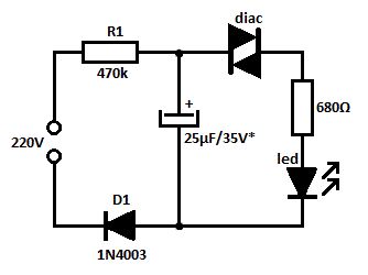
This is a simple blinking led circuit powered from 220V that can be used to mark special places or as voltage indicator. The voltage from the mains charges the capacitor through R1 resistor and D1 diode.
As long as the capacitor’s voltage doesn’t exceeds the diac’s switching voltage the cap is acting as a blocked diode. After reaching the switching voltage the diac is conducting and the cap’s discharging current lights up the LED.The blinking frequency of the LED depends mostly on the RC time constant (in this case T = 11 seconds). The capacitor’s voltage must be a little bit higher than the diac’s breakover voltage.
220 volts blinking LED schematic
With a 1N5758 diac the triggering voltage will be at 20V ± 2.?
5 Responses to “220V blinking LED circuit”
(View)
View full Circuit Diagram | Comments | Reading(3063)
12V battery level indicator circuit
Published:2012/9/18 21:22:00 Author:Ecco | Keyword: 12V, battery level indicator
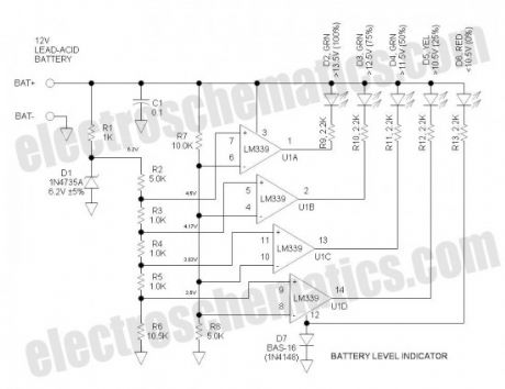

This battery level indicator offers (5) LEDs that light up progressively as the voltage increases:
Red: Power Connected (0%)
Yellow: Greater than 10.5V (25%)
Green 1: Greater than 11.5V (50%)
Green 2: Greater than 12.5V (75%)
Green 3: Greater than 13.5V (100%)
Of course, you may select your own colors if desired.
12 Volts Battery Level Indicator Circuit Schematic
Operation of the battery level indicator
D1 is the voltage reference zener. Tied to this is a string of divider resistors (R2-6) that set the various fixed voltage levels. R7 & 8 form a voltage divider to that reduces the battery voltage by a factor of 3. U1 is an LM339 quad comparator that compares the various voltages from the two dividers. The comparator sections have open collector outputs that simply function as switches to operate the LEDs. D7 protects against reverse battery connection.
The LEDs are biased to operate at about 4mA which is quite bright if modern LEDs are used. This current can be adjusted simply by varying the series resistors (R9 through R13). The overall current drain as shown is about 25mA which tends to be wasteful for continuous operation. For energy conservation, connect to battery via a pushbutton (Push to Test).
Printed Circuit Board
I did a www.expresspcb.com SMT layout using 0805 size components, 1N753 zener and SOIC-14 IC. D7 is in a SOT-23 package. These components are about as small as I like to work with. The layout has not yet been carefully checked or built. Note that surprises abound when constructing prototypes.The circuit board measures only 0.5” x 1.5”.
More recently, I located an inexpensive SOT-23 zener with a 2% voltage tolerance—this has not yet been incorporated.
I have had good results with 0805 size LEDs purchased from China on eBay. They are both inexpensive and BRIGHT!
The 12v battery level indicator unit in the photo has no reverse polarity diode and R2 is the calibration potentiometer.
6 Responses to “12V battery level indicator circuit”
Source: electroschematics.com
(View)
View full Circuit Diagram | Comments | Reading(2768)
Pathway Lighting with LEDs
Published:2012/9/18 21:22:00 Author:Ecco | Keyword: Pathway Lighting , LEDs
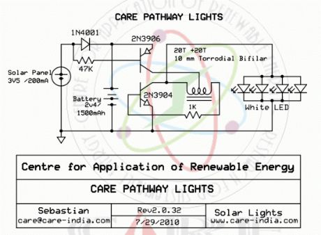
Simple pathway lighting that would provide illumination for the path at night. Extension for the Solar garden Light. The torroid is bifilar wound. The Torroid is 10mm and Cat 5 cable is wound around the same.
Solar panels of 3.5 maybe difficult to procure using 2 2V panels in series could be used. If you do use 4V panel then suggest you add another diode in series with 1N4001 to drop voltage to contain voltage to the battery.
The characteristic voltage for a white LED is 3.2V but the addition of the torroid provides the boost to drive the white LED. If you cannot procure the battery as suggested you can use 600 mAH battery then do not go above 3/4 LED’s.
Pathway LED Lights Schematic
?
7 Responses to “Pathway Lighting with LEDs”
(View)
View full Circuit Diagram | Comments | Reading(1970)
Firefly Lights Circuit
Published:2012/9/18 21:17:00 Author:Ecco | Keyword: Firefly Light
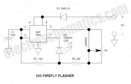

This firefly lights flasher is an easy, fun project.It can be built on the tiny circuit board, or on perf board.
Specifications
Battery life: approx 1year using the NXP 7555 CMOS timer IC & standard alkaline battery, or about 6months using the more common TI TLC555
Flash rate: approx 0.25hZ (unless using optional potentiometer)
Dimensions: 14.5mm2
Minimum voltage: approx 6V
Firefly flasher circuit schematic
Bill of Materials (if on perf board, use standard through-hole rather than SMT components)
PCB ExpressPCB.com
U1 NXP 7555 or TI TLC555 Timer IC, SOIC-8
R1 10K, 0805
R2 2M, 0805
R3 Potentiometer, 1M , 0.2” lead spacing (optional)
C1 10uF, 25V, X7R, Ceramic, 0805
D1 Diode, BAS16, or MMBD4148, SO23-3
D2 LED, Green, High Brightness, 0805
Battery Standard 9V
How the firefly lights works
It functions like almost any 555 astable timer, except that the LED is inserted into the capacitor reset path so that when pin 7 discharges C1 to common, this relatively high current must pass through the LED. In this way, the average battery current is only about 100uA. When battery voltage becomes very low, the LED threshold voltage prevents discharging C1 down to the lower threshold—when this happens, R2 finishes off the discharge because the output switches to ground potential the same time pin 7 turns on—you will find that this works on almost dead batteries that may be useless for other applications. D1 protects against accidental reverse battery voltage.
Background
Fireflies are common through Northeastern US and also in many other parts of the world. This green LED has the same color, flashes at about the same duration and has a similar repetition rate just like a real firefly (lightning bug). Put a number or these around your grounds and they will truly resemble fireflies—there will be no synchronization of the flashes. The only thing this cannot do is to fly—fireflies ascend as they flash, and they do not flash when perched to protect from predators. Also, this is much larger than the tiny firefly beetle that measures about 3 x 20mm.
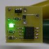
Photographs
Visible on the photo is a wire jumper connecting R2 to IC pin 3. This was an afterthought when I found that low voltage operation was poor. The PCB file is updated to fix this. The optional resistor is not used in this case, but is easy to add if desired. You may adjust component values to obtain desired results.
For the Future
Make it extinguish during daylight hours thus doubling battery life to 2years.
Happy experimenting!
2 Responses to “Firefly Lights Circuit”
Source: electroschematics.com
(View)
View full Circuit Diagram | Comments | Reading(1439)
Programmable Unijunction Transistor Flasher
Published:2012/9/18 21:15:00 Author:Ecco | Keyword: Programmable Unijunction , Transistor Flasher
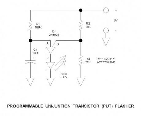
This is simple circuit that illustrates the function of the programmable unijunction transistor. It may be quickly wired on a proto-board.
PUT Flasher Specifications
Flash rate: approx 1hZ
Load current: approx 300uA
Minimum voltage: approx 4V
PUT Flasher Circuit Schematic
How it works
The programmable unijunction transistor remains dormant until the voltage across C1 exceeds the gate voltage of Q1 by one diode drop (0.6V) or in this circuit about 6.8V in reference to circuit common. At this point, current starts to flow into the anode of Q1. When the current exceeds the “peak current” threshold (about 1.25uA), the transistor triggers and shorts all three terminals together until the anode current drops below the “valley current” (about 100uA in this case), and the transistor resets itself. When the transistor triggers, it dumps capacitor C1 across the LED. Peak current is limited by the LED internal resistance.
By varying (programming) the gate voltage, the voltage at which the transistor fires varies—in this case, it varies the flash rate.
Background
This cute little device was developed by General Electric about 50years ago. The original GE part numbers were D13K1 and D13K2 (now 2N6027 and 2N6028). The 2N6028 has tighter specifications for more precision applications. On Semiconductor is now the sole manufacturer, but NTE has a relatively expensive equivalent device.
PUT Applications
There are many, many applications for this device, but it is mainly useful for triggering thyristors. Other than for thyristor triggering, the ubiquitous 555 timer has taken over.
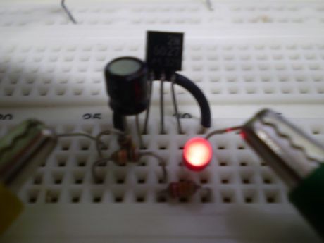
Photographs
Proto-board circuit layout
For the Future
Use of this device in a thyristor switch circuit
Bill of Materials
Q1 On Semiconductor 2N6027 (comes only in T0-92 package)
R1 100K
R2 10K
R3 22K
C1 10uF, 25V aluminum electrolytic
D1 LED Red, High Brightness
Battery Standard 9V ?
One Response to “Programmable Unijunction Transistor Flasher”
(View)
View full Circuit Diagram | Comments | Reading(2538)
Security Light & Switch with PIR Sensor Update
Published:2012/9/18 21:15:00 Author:Ecco | Keyword: Security Light, Switch , PIR Sensor Update

This is a simple update to Mr. Hareendran’s PIR Sensor Security Light circuit. It has a shortcoming limits the relay voltage to approximately 3.3V. While this may function with some 5V relays, it will not function with all. The nature of an emitter follower Darlington forces the output voltage to be two junction drops below the base drive voltage plus a small voltage drop across R1.In keeping with the spirit of his design, I retained the Darlington arrangement, and the transistor type number—however, I changed the transistors from common collector to common emitter configuration, and connected the relay between the collector output and the positive rail. The relay now utilizes a 12V coil—to use an existing 5V relay, simply add a resistor in series with the coil whose value is scaled up from the coil resistance. Also, I connected the LED across the relay coil rather than powering it via the 2nd relay contact—this way, only one form “C” relay contact is required thus making the relay less expensive—of course it can be done either way. I eliminated some additional, unneeded components.
Security Switch & Light Circuit Schematic
Datasheet links
SB0061 PIR Sensor (complete PIR module):epled-2008.en.made-in-china.com/BISS0001 PIR Sensor (interface IC that goes inside many PIR modules):http://www.ladyada.net/media/sensors/BISS0001.pdf
How it works
When motion is detected, the output (pin 2) goes to 5V and current flows through R2 to the base of Q1. The emitter current of Q1 becomes the base current of Q2—the current gain of a Darlington is the hFE squared or about 10,000 to 50,000 (very high). This easily provides adequate drive current for the relay. R1 provides a means of conducting any potential leakage in Q1 to common and also helps Q2 to turn off faster. D1 is the back diode that circulates the relay coil current when Q1 & Q2 turns off thus preventing a damaging voltage transient.
Testing
No, I did not build and test this one—I just happen to know from experience that this circuit will work OK—if the circuit was new to me, I would definitely Protoboard and test because Murphy may be lurking somewhere. Murphy’s Law states that anything that can go wrong will go wrong… Such is true as I have proven it numerous times.
For the Future
PIR crystal amplifier circuit—yes, it is not difficult. (View)
View full Circuit Diagram | Comments | Reading(1620)
The annular scintillator schematic
Published:2012/9/17 1:08:00 Author:Ecco | Keyword: annular scintillator
The circuit is mainly composed of NE555, CD4017 and peripheral circuits. The NE555 forms multivibrator, and its pin 3 outputs square wave to control CD4017 output shift end and individually light LED so that the LED ring flashes. As shown in the figure, the line flicker frequency is about 1.5Hz, operating current is less than 50mA.
Components Selection: IC1 chooses the 555 tine-base circuit, IC2 selects CD4017 integrated circuit. R1 uses (1/2) W metal film resistor, the remaining resistors selects (1/4) W resistors, LED0 ~ LED9 can choose Φ5mm ultra bright or special highlight red light-emitting tube. Other components are shown as the figure.
(View)
View full Circuit Diagram | Comments | Reading(1449)
Free energy Bicycle lights
Published:2012/9/16 21:49:00 Author:Ecco | Keyword: Free energy, Bicycle lights
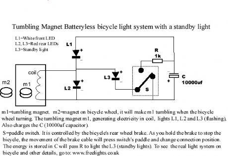
This bicycle safety flashing light system is based on a newly invented electrical generating system, NO battery needed, No friction on any parts of the bicycle. No drag. get the energy almost free (at least on bicycle). Very bright. Standby light. (View)
View full Circuit Diagram | Comments | Reading(4142)
Capacitor buck driving LED circuit 3
Published:2012/9/13 1:56:00 Author:Ecco | Keyword: Capacitor buck , driving , LED
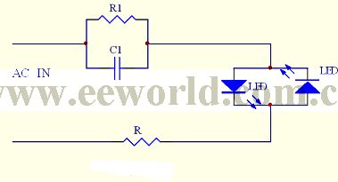
The circuit usestwo anti-parallel LEDs to rectify AC buck voltage, and itcan be widely used in night light, button indicatorlight, position indicator and other occasions.
(View)
View full Circuit Diagram | Comments | Reading(2315)
Advanced bicycle lighting Schematic
Published:2012/9/12 21:16:00 Author:Ecco | Keyword: Advanced, bicycle lighting
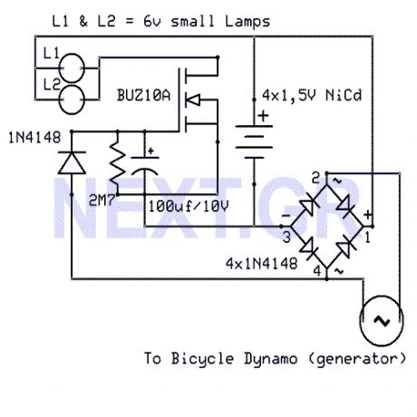
That Circuit is an advanced bicycle lighting system which will power your lights and also charge four NiCd batteries while you running in the streets, for keeping the lights on while the bicycle is stoped. Its fully automated without any switches.
Source: NEXT.GR (View)
View full Circuit Diagram | Comments | Reading(1876)
CAR STOP LIGHT
Published:2012/9/11 20:58:00 Author:Ecco | Keyword: CAR, STOP, LIGHT
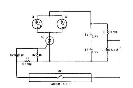
Capacitor Cl is connected continuously through the supply of 3 volts to 10 megohm resistor Rl. The capacitor is charged (relatively slowly) to 3 volts. The wink SWI is closed, it connects the charged capacitor (Cl) in series with C2 and R2. The capacitor C2 begins to charge, by placing a positive voltage during the gate of the SCR and turn it on. The two parallel self-flashing bulbs I1 and 12 on Tum. They flash on and off the SCR and the circuit is turned off until the vehicle is driven off the switch and C1 can recharge. (View)
View full Circuit Diagram | Comments | Reading(1808)
Xenon Lamp Flash Detector
Published:2012/9/10 20:52:00 Author:Ecco | Keyword: Xenon Lamp , Flash Detector
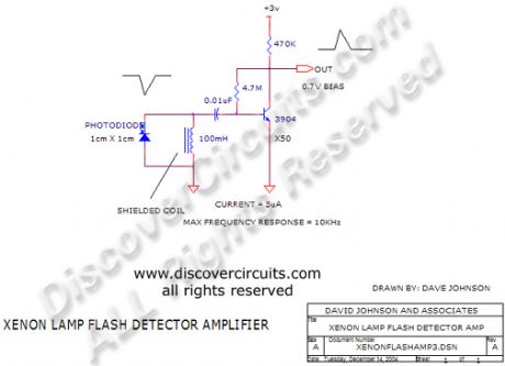
This circuit has a very low standby current requirement yet has very high sensitivity toward the light flashes from a xenon lamp. When connected to a flip/flop it can serve as an on on/off controller.
Source: discovercircuits (View)
View full Circuit Diagram | Comments | Reading(2004)
Gated automatic lamp circuit ( 1)
Published:2012/9/9 22:41:00 Author:Ecco | Keyword: Gated , automatic lamp
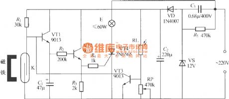
It is not convenience to find light switch when you return home at night. As shown in the figure, it is a gated automatic light, when you return home and open the door at night, the indoor lights will be turned on and turned off automatically after 50s, and it is blocked in the daytime and will not be illuminated. Gated automatic lighting circuit is shown as the figure, it consists of door and window sensor, delay circuit, light control circuit and power supply circuit. K can be used the JAG-4H dry reed pipe, small magnets should use small magnetic steel with strong magnetism.
(View)
View full Circuit Diagram | Comments | Reading(1456)
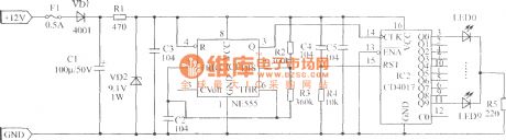
Four-way flashing light string circuit ( 2 )
Published:2012/9/9 22:52:00 Author:Ecco | Keyword: Four-way , flashing light string
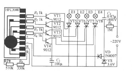

As shown in the figure, it is four-way flashing light string controller with a four-way gradually dimming light-emitting diode driver integrated circuit. The HFC3484 Manifold produced by Wenzhou Fenghua Electronic Co., Ltd. is dedicated to four the lights slowly fading flashing chip for the light-emitting toys. VT5 ~ VT8 can use small plastic unidirectional thyristor MCR100-8 ( 1A/600V ); each group's power of Lanterns E1 ~ E4 can not exceed 100W. The relationship between HFC3484 Manifold's external resistor R and output cycle T is shown in the following table:
(View)
View full Circuit Diagram | Comments | Reading(2268)
| Pages:21/72 At 202122232425262728293031323334353637383940Under 20 |
Circuit Categories
power supply circuit
Amplifier Circuit
Basic Circuit
LED and Light Circuit
Sensor Circuit
Signal Processing
Electrical Equipment Circuit
Control Circuit
Remote Control Circuit
A/D-D/A Converter Circuit
Audio Circuit
Measuring and Test Circuit
Communication Circuit
Computer-Related Circuit
555 Circuit
Automotive Circuit
Repairing Circuit