
LED and Light Circuit
Index 36
MODEL_ROCKET_IGNITION_CIRCUIT
Published:2009/7/13 22:10:00 Author:May
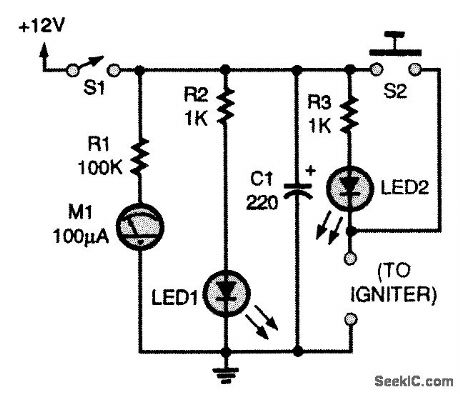
This circuit requires a 12-Vdc source. A battery pack of eight AA cells in series will work. Meter M1 gives you an indication of battery voltage; change the batteries when you see a noticeable drop in current. The circuit contains two LEDs: LED1 reminds you that the circuit is powered up, and LED2 lets you know that you have continuity through the igniter and are ready to fly. Capacitor C1 gives igniters that extra kick they occasionally need. Pushing the momentary push-button switch (S2) sends the rocket on its way. Use a red switch for that. The igniter leads are connected to the plugs marked igniter. (View)
View full Circuit Diagram | Comments | Reading(1224)
BIQUINARY_DECADE_WITH_NIXIE_INDICATORS
Published:2009/7/13 21:44:00 Author:May
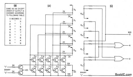
Transistor terminals 0 to 9 represent connections to Nixie indicator. Which requires no buffers. Counting rate can exceed 500 Mc, using 2N2708 transistors. Bi-quinary decade connections, shown at right and in table, permit easy conversion to bcd. –R. Engelmann. B-Quinary Scaling: Accuracy and Simplicity at 500 Mc. Electronics.36:46,p34-36. (View)
View full Circuit Diagram | Comments | Reading(976)
ACTIVE_HIGH_TRIAC_INTERFACE
Published:2009/7/13 21:34:00 Author:May
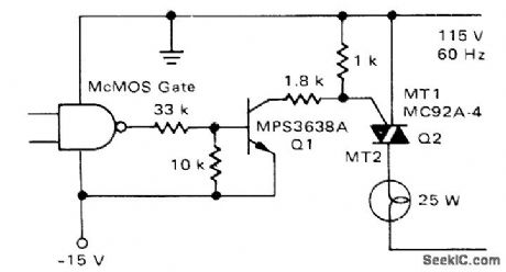
Typical CMOS logic gate operating from negative supply triggers triac on negative gate current of 8mA for control of 25-W AC load. High supply lines for both logic gate and interface transistor are grounded.-A.Pshaenich, Interface Techniques Between Industrial Logic and Power Devices, Motorola, Phoenix, AZ, 1975, AN-712A, p 12. (View)
View full Circuit Diagram | Comments | Reading(1232)
BATTERY_OPERATED_FLUORESCENT_LIGHT
Published:2009/7/13 21:00:00 Author:May
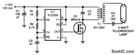
The circuit consists of a 20-kHz oscillator, a switching transistor to amplify its output, and a step up transformer. A 120- to 6-V power transformer is connected backward, using half of the 12-V side for 6 V. In the circuit, the transformer is working at considerably more than its rated voltage, but the high frequency keeps it from saturating. Although the lamp does not glow at full brightness, the circuit is energy-efficient, requiring only 150 mA. (View)
View full Circuit Diagram | Comments | Reading(3057)
BASIC_BAR_GRAPH_DISPLAY_CIRCUIT
Published:2009/7/13 20:30:00 Author:May
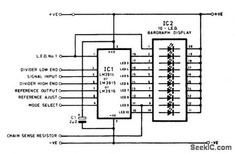
An LM3914 is shown connected to an LED bar-graph display. (View)
View full Circuit Diagram | Comments | Reading(2553)
VARYING_LCD_BIAS_CIRCUIT
Published:2009/7/13 20:29:00 Author:May
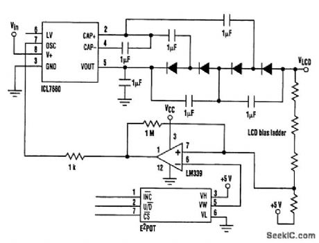
Large dot-matrix LCD drivers require a negative bias voltage of up to 24 V, depending on the LCD multiplex ratio One alternative is to combine the 7660 with a diode/capacitor voltage multiplier, using the 7660's internal square-wave generator as the signal source. This circuit will deliver an output of 37Vin-4Vf, thus generating approximately 24 V from a 9-V input. Additional stages could be added to the multiplier to allow 24 V to be generated from a 5-V regulated supply. In this circuit ,the output voltage is set by the input voltage, which might be inconvenient. If a variable voltage is required for contrast adjustment, Some form of microprocessor control over the output Voltage will be needed. One particular configuration used a Xicor E2POT to control the output by using a feedback circuit that pulls the oscillator pin of the 7660 low when the bias voltage exceeds the desired levels. This prevents further pumping of charge until the output returns to the required voltage The out-put ripple is set by the hysteresis resistor in the comparator circuit. (View)
View full Circuit Diagram | Comments | Reading(2180)
BAR_GRAPH_DISPLAY
Published:2009/7/13 20:26:00 Author:May
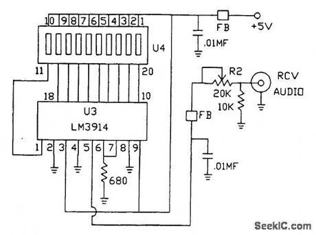
This bar-graph display monitors received audio level and can be useful for tuning, peaking, etc. (View)
View full Circuit Diagram | Comments | Reading(952)
TRICOLOR_LED_SIGN_DISPLAY
Published:2009/7/13 20:25:00 Author:May
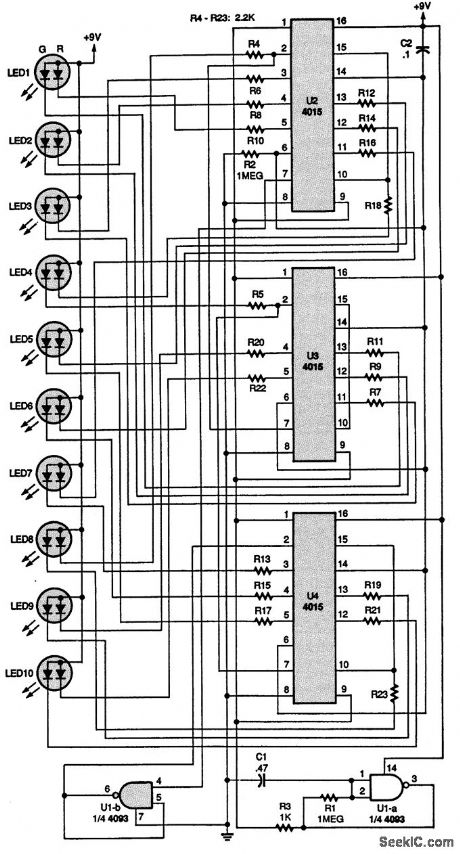
The purpose of this circuit is to light three-terminal LEDs in sequence on a small sign for a model railroad. Capacitor C2 is connected to the resets of the three 4015 shift registers, U2 to U4. When the circuit is first turned on, C2 automatically sets all the outputs to 0, thus inputting a 1 through U1-b, a section of a 4093 NAND Schmitt trigger, to the A input (pin 7) of U2. The circuit is clocked by U1-a, which is connected as an oscillator, and U1-a inverts the 0s to 1s until the first 1 is recirculated to the output of the last shift register, U4. Then the 1s become 0s and they recirculate. That all repeats as U1-a clocks the shift registers. When the first 1 is received at the first output of U2, the LED segment connected to it lights. As U1-a clocks the shift register, the LEDs connected to the other outputs sequentially light up red. After ten clock cycles, the clock skips two, and then continues lighting up the green segments of the LEDs, giving a yellowish-orange tint to them. After all the LEDs are lit, the shift register starts turning off the red LED segments. That leaves the green segments on-the third color from the LEDs. The oscillator continues to clock the green LEDs off, leaving the sign dark. After that cycle is completed, the operation repeats, giving the effect of a sign that goes from red to yellow to green to dark. (View)
View full Circuit Diagram | Comments | Reading(2557)
ALTERNATING_COLOR_LED_LIGHT_STRING
Published:2009/7/13 20:24:00 Author:May


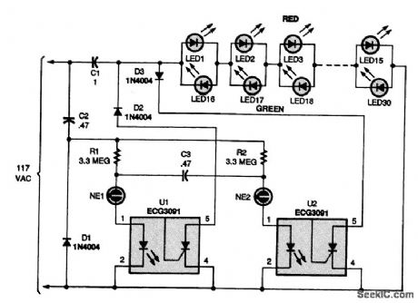
This circuit produces a string that alternates between red and green at a steady 1-s rate, making it an attractive addition to any holiday display. Two neon bulbs, NE1 and NE2, are connected in a relaxation-oscillator circuit that switches back and forth at about a 1-Hz rate. The values of R1, R2, and C3 set the switching rate. Dc power for the neon oscillator circuit is supplied via C2 and Dl. No dc filter capacitor is used or needed. When NE1 turns on, current flows through the LED in U1, an optocoupler, turning on the SCR and grounding the anode of D2. Only the positive half cycle of the ac waveform passes to the LEDs, which lights only the red ones (LED1 to LED15). After about 1 s, NE1 turns off and NE2 turns on, causing U2 to ground the cathode of D3. Now only the negative half cycle of the ac waveform passes to the LEDs, which lights only the green ones. If you'd like a change rate of less than 1 s, lower the values of R1 and R2 ; to lengthen the rate, increase the value of capacitor C3. (View)
View full Circuit Diagram | Comments | Reading(1246)
LED_BAR_GRAPH_CIRCUIT
Published:2009/7/13 20:22:00 Author:May
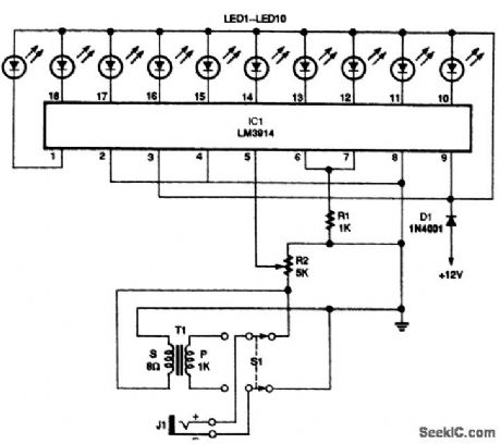
This circuit uses an LM3914 with either dc or audio input. R2 controls the input level. The display can be either ten discrete LEDs or a bar-graph LED assembly. (View)
View full Circuit Diagram | Comments | Reading(2188)
LED_DC_LEVEL_INDICATOR
Published:2009/7/13 20:21:00 Author:May
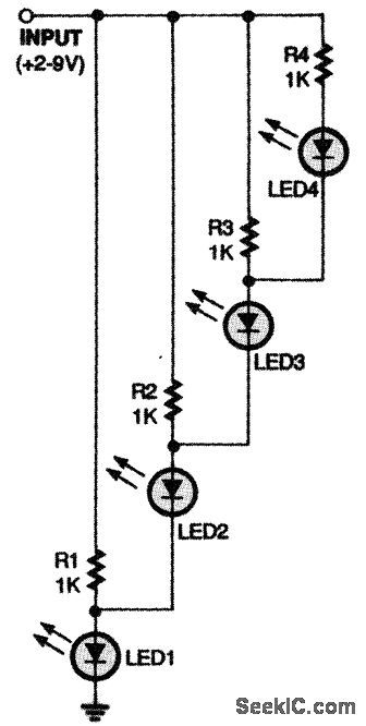
Here's a simple dc-level indicator (View)
View full Circuit Diagram | Comments | Reading(1049)
LED_LIGHT_STRING
Published:2009/7/13 20:21:00 Author:May
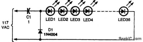
Capacitor C1, a 1-μF, 400-V Mylar or similar unit, operates in the circuit as a no-loss, ac-limiting component connected in series with the LED string. The capacitor's reactance acts like a transistor to the ac without the losses found with a standard power resistor. The 1N4004 silicon diode protects the LEDs from reverse-voltage damage. The circuit was tested with 36 red and green LEDs with an operating current of about 15 mA. Additional LEDs might be added in series if you wish, but that will reduce the brilliance of the LED string somewhat. (View)
View full Circuit Diagram | Comments | Reading(1585)
DUAL_COLOR_LED_LIGHT_STRING
Published:2009/7/13 20:18:00 Author:May
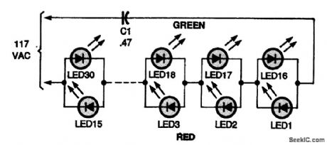
The red LEDs are lit during the positive transition of the ac waveform, and the green ones are lit during the negative transition. (View)
View full Circuit Diagram | Comments | Reading(1160)
DUAL_LED_LIGHT_STRING
Published:2009/7/13 20:17:00 Author:May
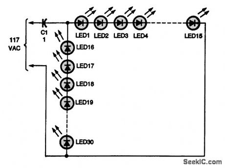
This circuit lets you light up two separate 15-light strings from a single power source. On the positive half cycle of the 60-Hz ac waveform, LEDs 1 through 15light, and on the negative half cycle, LEDs 16 through 30 light. Because the eye's response is much slower than 60 Hz, both strings appear to be on at the same time. (View)
View full Circuit Diagram | Comments | Reading(1096)
VARIAVLE_FREQUENCY_LED_FLASHER
Published:2009/7/13 20:17:00 Author:May
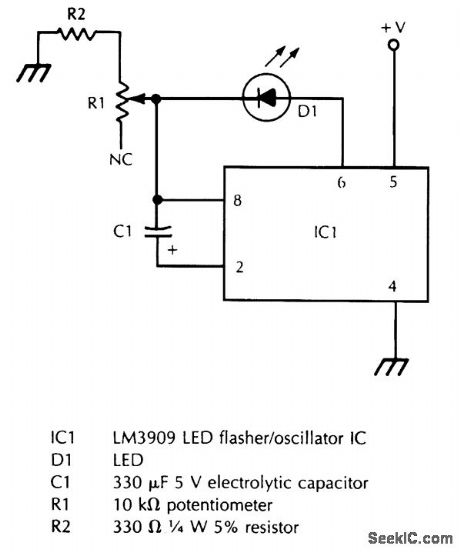
R1 varies the flash rate, and R2 limits the minimum resistance in the potentiometer circuit to prevent damage to D1 or IC1. (View)
View full Circuit Diagram | Comments | Reading(767)
NEON_LAMP_FLASHER
Published:2009/7/13 20:13:00 Author:May
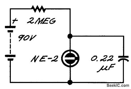
The neon lamp has negative dynamic resistance-the voltage across it falls while conduction is increasing. As a result, it flashes on and off. (View)
View full Circuit Diagram | Comments | Reading(993)
THRIFTY_LED_FLASHER
Published:2009/7/13 11:51:00 Author:May
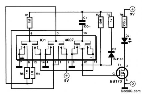
The dual complementary pair of switching FETs and inverter contained in a CD4007 CMOS IC enables an LED flasher to be made that uses very little energy. The IC is arranged as a three-inverter oscillator. Resistors R4 and R5 in series with the drains of one pair of FETs ensure that the drive current for the following pair of FETs is tiny. The high time of the oscillator is determined by network R3-C1, and its low time by R2-C1 (D1 is then cut off so that R3 is inactive). The LED is provided with current during the high time of the oscillator by T1. The level of this current is determined by R6.The values of R2,R3, and C1 cause an LED OFF time of 1 s and an ON time of 1 ms. Because the high-efficiency diode draws a current of30 mA, its lighting will be clearly visible. A standard 9-V battery will give continuous operation for about three years. (View)
View full Circuit Diagram | Comments | Reading(2771)
15_V_LED_FLASHER
Published:2009/7/13 11:48:00 Author:May

The LM3909 is one of the easiest-to-use LED flashers around. It can run for years using a stan-dard D cell. (View)
View full Circuit Diagram | Comments | Reading(0)
LIGHT_FLASHER
Published:2009/7/13 11:47:00 Author:May
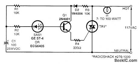
Shown here is a simple flasher circuit. With the component values shown, the flash rate is approximately once per second. The incandescent-lamp load glows at half brightness for about one-third of the total flasher period and is off for the remaining two-thirds. Electrolytic capacitor C1 charges during the positive half-cycle of the ac waveform through R1, R3, and D2. When the voltage across the capacitor reaches the break-over voltage of the silicon asymmetrical switch (SAS1), the capacitor starts to discharge through R2, SAS1, Q1, R4, and the triac. Emitter follower Q1 is driven by the discharge current from C1, and it, in turn, provides gate drive for the triac. Thus, the triac conducts and the light glows while C1 discharges. The lamp goes dark when C1 is depleted of charge and remains dark until the ac power waveform goes positive again and charges the capacitor sufficiently. The triac should be triggered into conduction by a gate current of no more than 5 mA. The flash rate can be varied by changing the value of capacitor C1. Using more capacitance results in a slower flash rate, and less capacitance results in a faster flash rate. (View)
View full Circuit Diagram | Comments | Reading(1118)
MULTIPLE_FLASHING_LED_LIGHT_STRING
Published:2009/7/13 11:44:00 Author:May
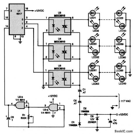
This circuit offers up to 10 strings of LEDs that turn on one row at a time in a sequential manner; for the sake of space and simplicity, only three strings are shown. The LED pairs could be all one color, mixed red and green, or any combination of colors. C2, C4, and D1 to D3 make up a 12-Vdc power supply for the five ICs. Two gates of a 4011 quad two-input NAND gate, U2-a and U2-b, are connected in a low-frequency oscillator circuit. Resistor R1 controls the oscillator's frequency.The oscillator supplies a clock output to U1, a 4017 decade counter/divider, which operates as a counter that can be programmed to count from 0 to 9. With each clock pulse, the 4017 makes a single step up in count from 0. The first output, at pin 3, supplies voltage to the LED in U3, a 3010 optocoupler, turning on the IC's triac and lighting the first string of LEDs. The next clock pulse steps the 4017 to the next output, at pin 2, and repeats the sequence for that string. As each new lightstring turns on, the preceding string turns off, giving the effect of a climbing string of lights. Changing the setting of R1 will change the rate at which the strings turn on and off. If you want to add additional light strings beyond what is shownin the figure, simply duplicate the circuitry for the light strings as shown and connect to the appropriate output of the 4017, U1. You will also have to connect the first unused output to pin 15. If you use the maximum of 10 strings, pin 15 should be connected to ground. (View)
View full Circuit Diagram | Comments | Reading(1910)
| Pages:36/72 At 202122232425262728293031323334353637383940Under 20 |
Circuit Categories
power supply circuit
Amplifier Circuit
Basic Circuit
LED and Light Circuit
Sensor Circuit
Signal Processing
Electrical Equipment Circuit
Control Circuit
Remote Control Circuit
A/D-D/A Converter Circuit
Audio Circuit
Measuring and Test Circuit
Communication Circuit
Computer-Related Circuit
555 Circuit
Automotive Circuit
Repairing Circuit