
LED and Light Circuit
Index 26
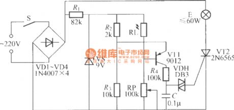
Double-key touching lamp switch circuit (9)
Published:2012/7/27 1:15:00 Author:Ecco | Keyword: Double-key, touching lamp , switch
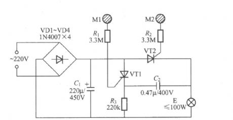
In the Figure , VT1, VT2 can use 2N6565, BT169 small plastic unidirectional thyristor. In this circuit, it you choose the appropriate resistance of R3, whne the lights are turning off, after the manpower leave the M1, VT1 can be turned off automatically because the anode currentflowing through the the VT1is too small, thereforeto save power consumption of the circuit.
(View)
View full Circuit Diagram | Comments | Reading(2753)
Night automatic lighting circuit with bidirectional thyristor
Published:2011/8/29 1:25:00 Author:Jessie | Keyword: bidirectional thyristor, lighting circuit
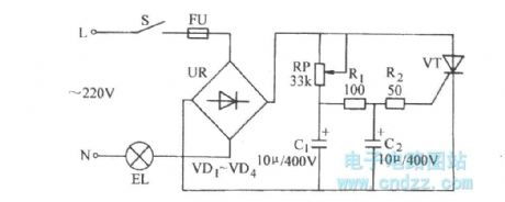
When the sunshine is very strong,light activated triode L14C1 will be connected. Diode VD3 is connected, which makes voltage of capacitor C2 decline to zero. Two-way trigger tube VD5 and two-way thyristor VT are not connected, the light is not on.
(View)
View full Circuit Diagram | Comments | Reading(1531)
65W fluorescent light using 24V chopper
Published:2011/12/1 21:09:00 Author:May | Keyword: 65W fluorescent light, 24V chopper
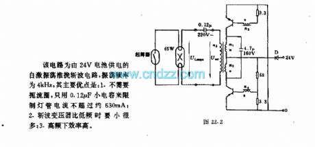
This circuit is self-oscillation push pull chopper circuit. It is supplied from 24V battery. Its frequency is 4kHz. Its major advantages are: 1. It does not require choke, and it only uses 0.12μF small-capacity capacitor to limit lighting tube current to belower than 630mA; 2. chopper transformer is much smaller than low frequency period; 3. when it isin high frequency, the efficiency is high.
Main technical data of the circuit:working volt: 24V working band: 4kHzcurrent sinking: 4.5Aconsumed power: 108Wlamp power: 65Wefficiency: 60%
Transformer data:n1=n2=10turns, 1.0mm copper lacquered wiren3=n4=2 turns, 0.75mm copper lacquered wiren5=120turns, 0.75mm copper lacquered wire (View)
View full Circuit Diagram | Comments | Reading(2110)
Photoelectric receiving amplifier circuit with LM307
Published:2011/8/30 22:28:00 Author:Jessie | Keyword: Photoelectric receiving amplifier
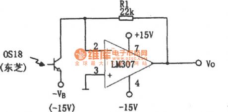
Photoelectric receiving amplifier is used to magnify photoelectric diode or light activated triode's output signals. When the light intensity of incident lightchanges, photodetector will produce corresponding voltage or current, and photoelectric receiving amplifier is used to amplify the photo-current changes, photoelectric receiving amplifier circuit with LM307 is the ideal device to realize the above role. If it adds offset voltage VB on light activated triode OS18, its output current in the illumination is Vo=IpR1. The photo-current Ip'sminimum is determined by LM307's input amplifier drift IB, Ip's maximum is determined by the maximum voltage output Vomax. (View)
View full Circuit Diagram | Comments | Reading(1814)
50kHz frequency light emission cuircuit
Published:2011/11/24 1:19:00 Author:May | Keyword: frequency light emission
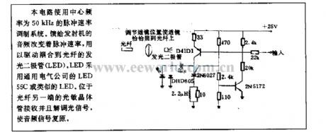
This circuit uses center frequency 50kHz impulse speed modulation system. Audio frequency feedback transmitter can change impluse speed, and it isused to drivethe LEDcoupled to optical fiber. LED uses General Electric LED 5C or similar LED. Optical transistor islocated on another end of optical fiber toreceive and demodulate light signal and make audio frequency recover.
(View)
View full Circuit Diagram | Comments | Reading(1014)
Lighting dimmer using thyristor AC power
Published:2011/8/28 21:58:00 Author:Jessie | Keyword: Lighting dimmer, thyristor, AC power
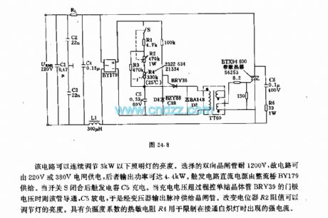
This circuit can continuously adjust lamp's brightness which below 3kW. The choosen Bi-directional thyristor can bear 1200V, so the circuit power can be supplied by 220V or 380V grid, the latter output power can reach 4.4 kW. Trigger circuit dc power is supplied by rectifier bridge BY179. When switch S is closed, trigger capacitor C5 is charging. When the recharging voltage is over BRY39's gate voltage, the pipe is connected, C5 is discharged, so transformer output pulse supplys for the thyristor. Changing the potentiometer R2 can adjust the brightness of the light. (View)
View full Circuit Diagram | Comments | Reading(2667)
Ordinary thyristor dimming circuit
Published:2011/8/28 21:21:00 Author:Jessie | Keyword: thyristor, dimming
View full Circuit Diagram | Comments | Reading(1458)
Green trees and silver flowers christmastree circuit with singing christmas songs
Published:2011/11/10 3:00:00 Author:May | Keyword: Green trees and silver flowers, christmastree, singing christmas songs
View full Circuit Diagram | Comments | Reading(1308)
CS6061A Touching stepping dimmer circuit
Published:2011/11/10 21:33:00 Author:May | Keyword: Touching stepping dimmer
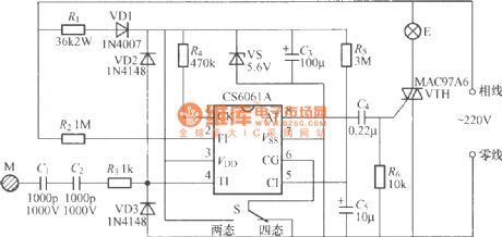
The diagram shows touching stepping dimmer circuit made of CS6061A integrated circuit. It has the function of two-four states switching, and its working performance is reliable. Moreover, it fits longer connecting line and larger touch tablet load (400pF). (View)
View full Circuit Diagram | Comments | Reading(1498)
Construction indicator light circuit diagram (CD4017、CD4011)
Published:2011/11/4 2:18:00 Author:May | Keyword: Construction indicator light
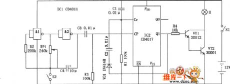
Construction indicator light circuit is shown in the diagram. It needs artificially power, after circuit geting power, theindicator light flashes without breaking toremind people topay attentionon safety.
(View)
View full Circuit Diagram | Comments | Reading(2200)
Festival flashing colorful light circuit composed of RY169
Published:2011/11/9 20:50:00 Author:May | Keyword: Festival flashing, colorful light
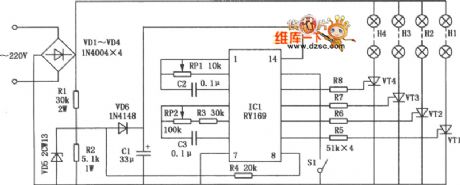
Festival flashing colorful light circuit is shown in the diagram. ACvoltage isfull-wave bridge rectified by diodes VD1~VD4, voltage regulated by resistors R1, R2 and voltage regulator diode VD5,filtered by capacitor C1 to generate 6V smooth DC voltage, and it is used for the whole circuit. Diode VD6 is used forisolation. IC1 is colorful light control application specific intergrated circuit RY169, andits internal structurehas brightness grade and output speed oscillators, and the oscillator frequency depends on RP1, C2 and RP2, R3, C3. After it gets power, IC1's pin 9~12 output changing pulseto passresistors R5~R8andadd to thyristors VT1~VT4's controlling electrodes, then its conduction angle changes, thereby it generates thestars flashing effect. IC3's pin 2 is the control end oflight chain lighting direction. (View)
View full Circuit Diagram | Comments | Reading(1244)
Fancy lantern circuit
Published:2011/11/10 1:15:00 Author:May | Keyword: Fancy lantern
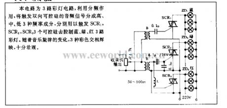
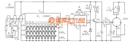
This circuit is 3-road fancy lantern circuit whichuses fractional frequency to divide trigger bidirectional thyristor audio frequency signal into high, middle, low, and they are usedseparately to trigger SCR1, SCR2, SCR3 controlled silicon to control blue, green, red fancy lanterns. With the change of music rhythm, three kinds ofcolor changes, and it is very impressive.
(View)
View full Circuit Diagram | Comments | Reading(1092)
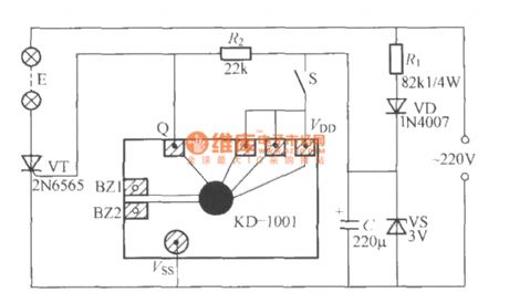
Gate controlling delay light circuit diagram
Published:2011/11/9 20:14:00 Author:May | Keyword: Gate controlling , delay light
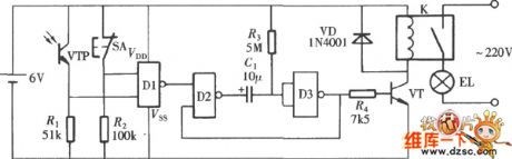
Gate controlling delay light uses gate switch to control the turning on or off of the lamp, during the day, the light can not be open because of light control. At night, if you open the door, at the same time, the lamp is turned onautomatically and delayed period of time,and the circuit is shown in the diagram. The circuit consists of a four-dual input end orNOT gate CD4001, among them, gate D1 makes up thelight control and trigger circuit, gates D2, D3and R3, R1 make up single shot trigger toplay a roleof delay close. Transistor VT and relay K are used as lamp EL's switch control circuit. Optical transistor VTP plays a role in light control.
(View)
View full Circuit Diagram | Comments | Reading(1139)
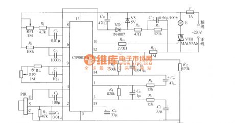
Pyroelectric infrared induction automatic lamp circuit 4(CS9803GP)
Published:2011/11/3 3:26:00 Author:Ecco | Keyword: Pyroelectric, infrared induction, automatic lamp
View full Circuit Diagram | Comments | Reading(2297)
The thyristor dimmer light circuit with stabilizing light function( 3 )
Published:2011/12/8 1:13:00 Author:Ecco | Keyword: thyristor , dimmer light , stabilizing light function
View full Circuit Diagram | Comments | Reading(2065)
The thyristor dimmer light circuit with stabilizing light function( 2 )
Published:2011/12/8 1:15:00 Author:Ecco | Keyword: thyristor , dimmer light , stabilizing light function
View full Circuit Diagram | Comments | Reading(1252)
Four-way flashing light string circuit ( 1 )
Published:2011/12/8 1:42:00 Author:Ecco | Keyword: Four-way , flashing light string
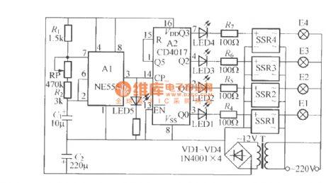
The circuitshown in the chart is the 4-wayflashing lights string controllerwhich uses a solid relay anddigital and other components, and the output power is larger, each driving power is up to 600W. SSR1 ~ SSR4 use SP110 solid-state relays.
(View)
View full Circuit Diagram | Comments | Reading(1302)
Single-way flashing light string circuit (4 )
Published:2011/12/8 1:45:00 Author:Ecco | Keyword: Single-way, flashing light string
The circuit shown in the chart is the single-way flashing light stringcontroller which usesthe music integrated circuit for musical greeting cards, andthe circuit is simple, the flashing is satisfied.
(View)
View full Circuit Diagram | Comments | Reading(1197)
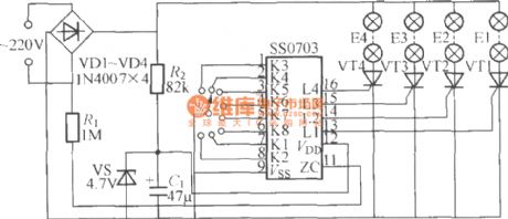
Four-way flashing light string circuit (12) (SS0703)
Published:2011/12/8 1:18:00 Author:Ecco | Keyword: Four-way, flashing light string
View full Circuit Diagram | Comments | Reading(1054)
Christmas light circuit
Published:2011/11/7 20:30:00 Author:Ecco | Keyword: Christmas light
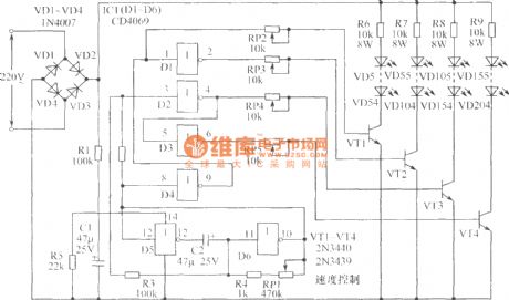
The chart shows the Christmas lights circuit which uses simple, inexpensive CD4069 CMOS hex inverter to control four circuits with 200 light-emitting diodes (each circuit has 50 LEDs), and it is directly supplied by the 220V power source without power transformer. The power is bridge rectified by VD1 ~ VD4, differential pressured by R1, R5 and filtered by C1, then the two ends of the C1 gets about 6V DC voltage for IC1 (CD4069). Gates D5 and D6 form the low-frequency oscillator. RP can adjust its frequency. The output is reversed-phase shaped by the combination with D1 ~ D4 to control 4 pieces of high back pressure transistors (2N3440/2N3439) VT1 ~ VT4.
(View)
View full Circuit Diagram | Comments | Reading(3329)
| Pages:26/72 At 202122232425262728293031323334353637383940Under 20 |
Circuit Categories
power supply circuit
Amplifier Circuit
Basic Circuit
LED and Light Circuit
Sensor Circuit
Signal Processing
Electrical Equipment Circuit
Control Circuit
Remote Control Circuit
A/D-D/A Converter Circuit
Audio Circuit
Measuring and Test Circuit
Communication Circuit
Computer-Related Circuit
555 Circuit
Automotive Circuit
Repairing Circuit