
LED and Light Circuit
Index 25
Color changing flashlight circuit diagram
Published:2012/8/29 22:07:00 Author:Ecco | Keyword: Color changing , flashlight
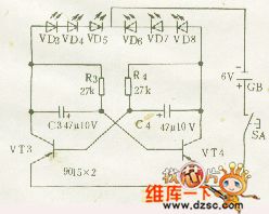
Multivibrator's two transistor collectors are connected to LED respectively, LED can flash alternately accoring to the cycles of multivibrator, this circuit is widely used such as home decorating. This circuit uses high-gain PNP germanium VT3,VT4 to form a multivibrator, there are two inverters are connected with beginning and end, and interstage uses capacitors C3,C4 for coupling, its working cycle is 1S. Transistor should choose the 9012 or 9015 with collecting electrode electric current being greater than 50mA, emitting tube should choose high-brightness tubes. If you want to change the flashing speed, you can adjust the capacity of C3,C4, or fine tune R3,R4 to change the corresponding resistance.
(View)
View full Circuit Diagram | Comments | Reading(1611)
Pyroelectric infrared sensor automatic lamp circuit ( 8)
Published:2012/8/28 22:38:00 Author:Ecco | Keyword: Pyroelectric infrared , sensor, automatic lamp

As shown in the figure, it is an infrared sensor automatically switch with TDH98072 ASIC, it uses two-wire connection to transformed the general lights into sensing automatically lamps, and the swicth can directly replace ordinary switch.
(View)
View full Circuit Diagram | Comments | Reading(1956)
Pyroelectric infrared sensor automatic lamp circuit (3)
Published:2012/8/28 22:55:00 Author:Ecco | Keyword: Pyroelectric infrared , sensor , automatic lamp
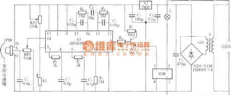
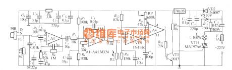
As shown in the figure, it is a sensing automatic lamp circuit using BISS0001 infrared sensing signal processing integrated circuit, the work is very stable and reliable, and it can be used in the bathroom, storage room, automatic lighting. PIR can use P228, PH5324, LH956 pyroelectric infrared sensors with installing Fresnel lens. SSR uses the JCX-2F-DC5V zero compact solid state relay, and it is compact and can be plugged and directly on the printed circuit board. Other components requirements are shown as the figure.
(View)
View full Circuit Diagram | Comments | Reading(5185)
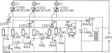
Thyristor three - color dimming light circuit
Published:2012/8/28 22:12:00 Author:Ecco | Keyword: Thyristor , three - color, dimming light
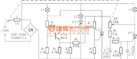
It only uses a potentiometer to control the on-off of red, green, blue three bulbs. VT1 ~ VT3 can use BT169D, 2N6565, MCR100 -8 small plastic one-way thyristor, E1 ~ E3 choose red, green, blue and other colored incandescent bulbs with power being lower than 60W accoring to personal favorites.
(View)
View full Circuit Diagram | Comments | Reading(2951)
Two-button FET dimming light circuit
Published:2012/8/29 0:55:00 Author:Ecco | Keyword: Two-button, FET , dimming light
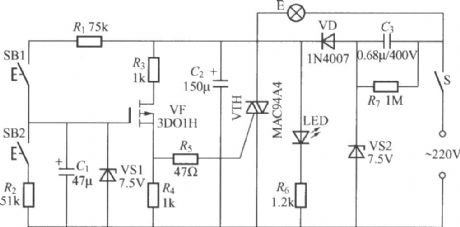
It uses two touching buttons switch fordimming, and one is used to highlight, the other is used to dim. Its advantagesinclude easy to use, beautiful appearance.
(View)
View full Circuit Diagram | Comments | Reading(1600)
LED bar graph display pressure gauge circuit with integrated Silicon pressure sensor MPX5100A
Published:2012/8/28 1:07:00 Author:Ecco | Keyword: LED, bar graph display , pressure gauge, integrated Silicon, pressure sensor
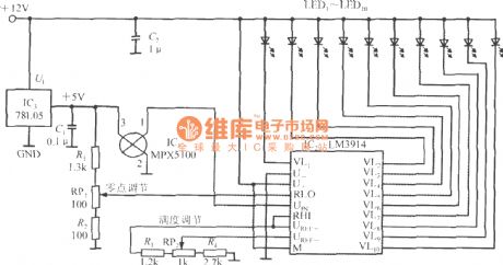
Its measuring range is 0~100kPa, resolution is 10kPa. +12V power can get +5V stabilized voltage output after passing three-side integrated voltage regulator 78L05, the maximum output current is up to 100mA, and it provides power for MPX5100 and LM3914. MPX5100's output voltage connects to UIN side of the LM3914. After the UREF+ end and RHI-side are connected in a short circuit, then UREF-end connects RP2, RP2 is full scale adjustment potentiometer. RP1 is zero scale adjustment potentiometer, when measured pressure is zero, adjusting RP1 can make all LEDs be hidden.
(View)
View full Circuit Diagram | Comments | Reading(3007)
Line status indicator
Published:2012/8/24 22:39:00 Author:Ecco | Keyword: Line status, indicator
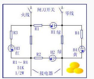
As shown in the figure, when the circuit is normal, H1, H2 glow, H3, H4 is not lit. When fuse on power line is blown, H3 is lit and H2 is extinguished. When the fuse on zero line blows, H4 is lit, H2 is extinguished. When two fuses are blown, H2, H3 , H4 are turned off, H1 is still lit. When H1, H2 shine, the applicance can not work properly, it shows that the device or the line after H2 is in failure. When fuse blows at night, H1 is also available for indoor shimmer lighting, allowing users to replace the fuse safety.Production: neon can use the neon bulb in fluorescent starter, its power consumption is minimal. If the neon bulb is pasted colored paper, it is easier to observe.
(View)
View full Circuit Diagram | Comments | Reading(1439)
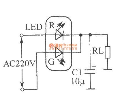
The circuit of LED full-wave rectifier
Published:2012/8/21 3:39:00 Author:Ecco | Keyword: LED, full-wave rectifier
View full Circuit Diagram | Comments | Reading(1162)
The microwave probe delay lighting circuit diagram with RD627
Published:2012/8/16 21:25:00 Author:Ecco | Keyword: microwave , probe , delay lighting
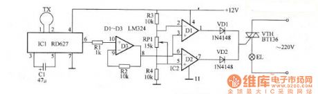
The microwave probe delay lighting circuit diagram with RD627 concistsofIC1, IC2 , and Triac VTH, and it is shown as the figure.
The internal circuit of IC1 is composed of oscillator , emission, amplifier, detector, limiter, delay and regulator circuits, and it has few external components, and loop antenna TX can be usedforemission and receiving. IC2 is usedas amplifier and comparator.
After the power is connected, antenna TX will launch the microwave signal out.When nobody comes intothe effective detection area ( an area of approximately 100m2), IC1's pin 6 outputs 6V, and IC2's pin 1 and pin 7 output low level, then diodes VD1 and VD2 are closed, the thyristor VTH is cut off because gate pole has no trigger voltage, and light EL is not bright.
(View)
View full Circuit Diagram | Comments | Reading(1209)
Three-way blinking light string circuit (1)
Published:2012/8/6 4:20:00 Author:Ecco | Keyword: Three-way , blinking, light string
The figure shows a three-way flashing light string controller which is simple and easy to make, and each way can drive power up to 600W. Ifthree-way light strings are arranged appropriately in space, it can form light liquidity effect visually.
(View)
View full Circuit Diagram | Comments | Reading(1482)
Thermal pyroelectric infrared sensing automatic light circuit (6)
Published:2012/8/6 4:14:00 Author:Ecco | Keyword: Thermal, pyroelectric , infrared , sensing , automatic light

As shown in the figure, it isa sensing automatically lightmade by newHN911L pyroelectric infrared detection module. The HN911L integrates high - sensitivity infrared sensors, PIR , amplifiers, signal processing circuit andoutput circuit. Itisable to remote sense the faint infrared signals from human motion. The lights can be turned on when people move around, turned off automaticallydelay tens of seconds when people leave.
(View)
View full Circuit Diagram | Comments | Reading(2874)
Thyristor double-tone dimmer circuit (1)
Published:2012/8/1 2:12:00 Author:Ecco | Keyword: Thyristor, double-tone dimmer
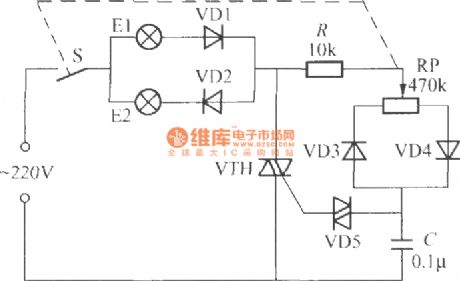
In the circuirshown as the figure, VTH canuse TLC221B or MAC94A4 bidirectional thyristor, VD1 ~~ VD4select 1N4007 silicon rectifier diodes, VD5 is 2CTS bidirectional trigger diode withrequiring the transition voltage being30 ~ 39V.
(View)
View full Circuit Diagram | Comments | Reading(1729)
Thyristor double-tone dimmer circuit (2)
Published:2012/8/1 2:10:00 Author:Ecco | Keyword: Thyristor, double-tone dimmer
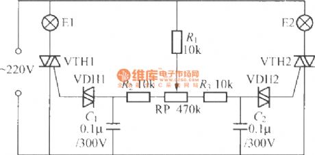
VTH1, VTH2 can use TLC221B MAC94A4, MAC97A6 small plastic bi-directional triode thyristors. VDH1, VDH2 use 2CTS bi-directional trigger diodes with requiring the transition voltagebeing 30 ~ 39V. The power of E1, E2 should be less 60W or 60W.
(View)
View full Circuit Diagram | Comments | Reading(3372)
Three-way blinking light string circuit (5)
Published:2012/8/1 2:32:00 Author:Ecco | Keyword: Three-way , blinking, light string
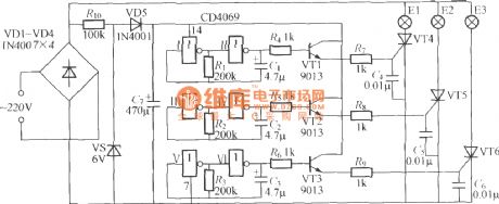
As shown in the figure, the three-way flashing light string controlleris made by a digital integrated circuit, and shiningchange of light string is random, unpredictable, very interesting.
(View)
View full Circuit Diagram | Comments | Reading(1453)
Thermal pyroelectric infrared sensing automatic light circuit (1)
Published:2012/8/1 2:20:00 Author:Ecco | Keyword: Thermal, pyroelectric, infrared , sensing , automatic light
As shown in the figure, the circuit is a pyroelectric infrared sensing automatic light which can be used for stairs walkways , bathrooms and other occasions. The lights can be turned on when people come, turning off when people leave, and the lights are automatically locked during the day, so the lamps will not be lit. The PIR can use P228 pyroelectric infrared sensor. In order to improve its sensitivity, it is best for their installation of the Fresnel lens, and the focus of the lens should be located in the sensingwindow of sensor. RP is the circuit delay time adjustment potentiometer, and it can also use an ordinary fixed resistor.
(View)
View full Circuit Diagram | Comments | Reading(1602)
Thermal pyroelectric infrared sensing automatic light circuit (10)
Published:2012/8/1 2:16:00 Author:Ecco | Keyword: Thermal, pyroelectric , infrared , sensing , automatic light

As shown in the figure, the circuit usesthe YB- 28 pyroelectric infrared sensor modules to make sensing automatic lights, and the circuit is very simple. Itcan easily achievethe effect of turing onthe lights when people come, off when leave.
(View)
View full Circuit Diagram | Comments | Reading(1661)
Thermal pyroelectric infrared sensing automatic light circuit (2)
Published:2012/8/1 2:26:00 Author:Ecco | Keyword: Thermal , pyroelectric , infrared , sensing , automatic light
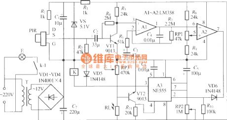
The figure shows a the pyroelectric infrared sensing automatic lights circuit with good performance. It uses relay to control light, soit can control theautomatically turning on of fluorescent lamps and automaticallycontrolling of incandescent lighting.
(View)
View full Circuit Diagram | Comments | Reading(1551)
Double-key touching lamp switch circuit (2)
Published:2012/7/27 1:21:00 Author:Ecco | Keyword: Double-key, touching lamp , switch

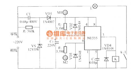
As shown in the figure, it is a double-key touching lamp switch circuit compoased of homemade optocoupler and thyristor rectifier circuit. V1 ~ V3can useNH-416, NHO-4L and other small neon bubbles; RL1 , RL2can selectMG45 photosensitive resistor. VTH1, VTH2 can use small plastic MAC94A4 or MAC97A6 bidirectional thyristor, and the power of controlled lamp E should be limited to be lower than 100W.
(View)
View full Circuit Diagram | Comments | Reading(1665)
Double-key touching lamp switch circuit (4)
Published:2012/7/27 1:18:00 Author:Ecco | Keyword: Double-key , touching lamp , switch
In the figure, K can use JZC- 22F DC12V small medium power electromagnetic relay, and other components have no special requirements.
(View)
View full Circuit Diagram | Comments | Reading(1427)
Double-key touching lamp switch circuit (8)
Published:2012/7/27 1:08:00 Author:Ecco | Keyword: Double-key, touching lamp , switch
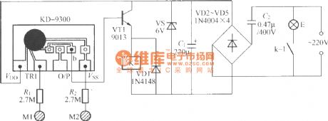
As shownin the figure, the circuitis made byan ordinary music doorbell chip. K can use JZC- 22F DC12V small medium power electromagnetic relay, and other components have no special requirements.
(View)
View full Circuit Diagram | Comments | Reading(1288)
| Pages:25/72 At 202122232425262728293031323334353637383940Under 20 |
Circuit Categories
power supply circuit
Amplifier Circuit
Basic Circuit
LED and Light Circuit
Sensor Circuit
Signal Processing
Electrical Equipment Circuit
Control Circuit
Remote Control Circuit
A/D-D/A Converter Circuit
Audio Circuit
Measuring and Test Circuit
Communication Circuit
Computer-Related Circuit
555 Circuit
Automotive Circuit
Repairing Circuit