
LED and Light Circuit
Index 41
RADIATION_ALARM
Published:2009/7/20 0:39:00 Author:Jessie
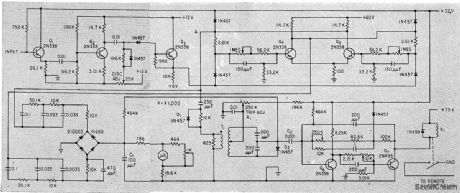
Input is from multiplier phototube having anthracene scintillation crystal on its window. Signals are amplified by Q1, Q2, and Q3, and fed to counter flip-flop Q4-Q5. Flip-f1ip output goes to logarith-mic count circuit whose output level is indi-cared by microammeter. When output exceeds predetermined level, alarm circuit closes relay that actuates audible and visual alarms.-H. E. DeBolt, How Radiation Monitor Guards Nuclear Navy, Electronics, 33:4, p 43-45. (View)
View full Circuit Diagram | Comments | Reading(1158)
Car_turn_signal_reminder
Published:2009/7/20 0:09:00 Author:Jessie
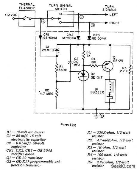
Car turn signal reminder. This circuit is designed for 12-volt negative ground systems only. For cars with a 6-volt negative ground system use a 6-volt buzzer. The circuit cannot readily be adapted for positive ground systems (courtesy General Electric Company). (View)
View full Circuit Diagram | Comments | Reading(1943)
Sequential_AC_flasher_using_SCRs_triacs_and_a_UJT
Published:2009/7/20 0:06:00 Author:Jessie
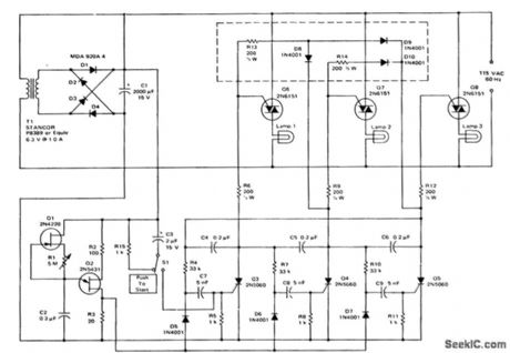
Sequential AC flasher using SCRs, triacs and a UJT. Only three stages are shown but many additional stages can be added. By adding the circuitry inside the dashed lines the circuitry can be modified so that the previous lamps remain on when a new lamp sequences on (courtesy Motorola Semiconductor Products Inc.). (View)
View full Circuit Diagram | Comments | Reading(1080)
15_volt_fast_blinker_using_an_LM3909
Published:2009/7/20 0:04:00 Author:Jessie
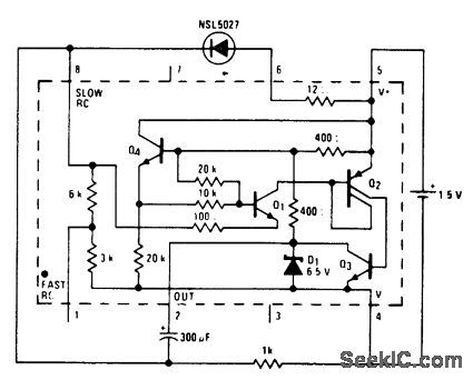
1.5-volt fast blinker using an LM3909. Flashing rate is about 3 hertz. Circuitry inside dashed lines is the LM3909 chip (courtesy National Semiconductor Corporation). (View)
View full Circuit Diagram | Comments | Reading(783)
1_kilowatt_flasher_with_photoelectric_control
Published:2009/7/20 0:03:00 Author:Jessie

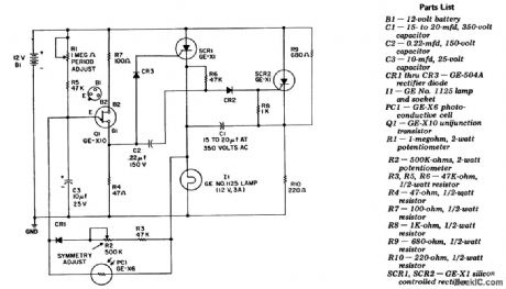
1-kilowatt flasher with photoelectric control. This circuit can be used to control warning lights on towers, piers or construction hazards. Remote control can be attained by adding neon lamp N2 and masking PC1 so that it sees only N2 (courtesy General Electric Company). (View)
View full Circuit Diagram | Comments | Reading(751)
12_volt_two_wire_automotive_flasher_using_an_LM3909_chip
Published:2009/7/19 23:57:00 Author:Jessie
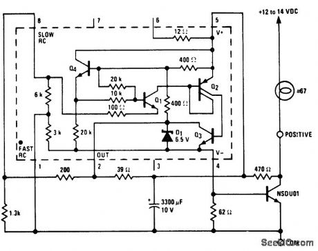
12-volt two-wire automotive flasher using an LM3909 chip. Circuitry inside dashes is the LM3909. Rate is about 1 hertz. Since it is a two-wire circuit it can be adapted for either negative or positive ground systems. In positive ground systems place the lamp between the common and the negative battery terminal (courtesy National Semiconductor Corporation). (View)
View full Circuit Diagram | Comments | Reading(1650)
SIGNAL_INJECTOR_1
Published:2009/7/10 1:30:00 Author:May
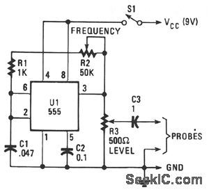
The unit provides a square-wave output that is rich in harmonic content. The circuit's output frequency can be varied from 50 Hz to 15 kHz. The heart of the circuit is a 555 astable connected in its equal mark/space mode. The frequency is controlled by potentiometer R2 and capacitor C1.Resistor R3 controls the output level with the output ac-coupled through C3.
(View)
View full Circuit Diagram | Comments | Reading(968)
6_volt_flasher_using_an_LM3909_chip
Published:2009/7/19 23:48:00 Author:Jessie

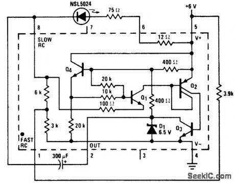
6-volt flasher using an LM3909 chip. Flashing rate is about 1 hertz. Circuitry inside dashed lines is the LM3909 (courtesy National Semiconductor Corporation).
(View)
View full Circuit Diagram | Comments | Reading(877)
Safe_high_voltage_flasher_using_an_LM3909
Published:2009/7/19 23:47:00 Author:Jessie
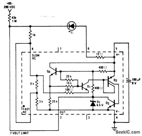
Safe high-voltage flasher using an LM3909. Circuitry inside dashes is the LM3909. If the 43K dropping resistor shown is employed the IC and LED will be about 7 volts above ground (courtesy National Semiconductor Corporation). (View)
View full Circuit Diagram | Comments | Reading(771)
15_volt_LED_flasher_using_an_LM3909
Published:2009/7/19 23:41:00 Author:Jessie
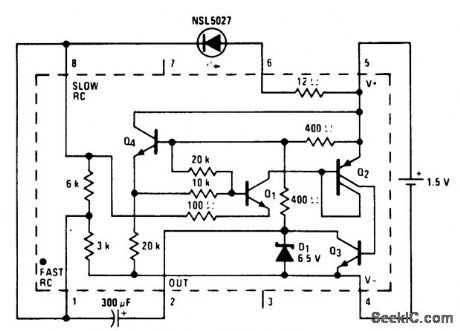
1.5-volt LED flasher using an LM3909. Flashing rate is about 1 hertz. Circuitry inside dashed lines is the LM3909 (courtesy National Semiconductor Corporation). (View)
View full Circuit Diagram | Comments | Reading(726)
3_volt_ministrobe_using_an_LM3909_chip
Published:2009/7/19 23:40:00 Author:Jessie
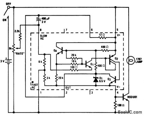
3-volt ministrobe using an LM3909 chip. Circuitry inside dashes is the LM3909. Flash rate can be varied from no flash to continuously on (courtesy National Semiconductor Corporation). (View)
View full Circuit Diagram | Comments | Reading(883)
High_power_battery_operated_flasher_with_40_watt_output
Published:2009/7/19 23:32:00 Author:Jessie
High-power battery-operated flasher with 40-watt output. SCR1 and SCR2 form a basic DC flip-flop (courtesy General Electric Company). (View)
View full Circuit Diagram | Comments | Reading(909)
Light_target_flasher
Published:2009/7/19 23:27:00 Author:Jessie
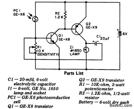
Light target flasher. Photoresistor PC1 starts the flasher circuit whenever light hits it. Sensitivity control R1 is adjusted so that the flasher stops whenever the light source is removed (courtesy General Electric Company). (View)
View full Circuit Diagram | Comments | Reading(788)
PROGRAMMABLE_SLOPE_INTEGRATOR
Published:2009/7/9 23:38:00 Author:May
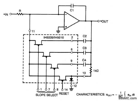
By using analog swi,ch IH5009/IH5010 to select various capattors, a variable slope integrator can be had.If C3=2(C2) and C4=4(C2), seven different slopes can be obtained if binary informatlon is fed to pins 1, 7, and 8 of the analog switch. (View)
View full Circuit Diagram | Comments | Reading(982)
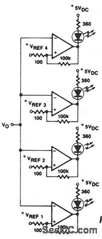
VISABLE_VOLTAGE_INDICATOR
Published:2009/7/9 23:26:00 Author:May
View full Circuit Diagram | Comments | Reading(781)
LIGHT_CHASER_II
Published:2009/7/9 23:08:00 Author:May
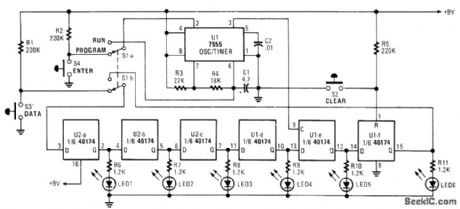
Up to six lights can be sequentially flashed using this circuit. LED1 through LED6 can be replaced by optocouplers (M0C3010, etc.) to control 120-Vac loads via triacs. U1 generates pulses that clock the shift register mode up of the six D flip-flops in the CD 40174. By S1A-B, the register can be programmed either ON or OFF (low or high) and then switched to nut in the programmed sequence. S2 clears the program. (View)
View full Circuit Diagram | Comments | Reading(2932)
LOW_VOLTAGE_INDICATOR
Published:2009/7/9 23:07:00 Author:May
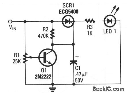
Input terminal VIN is connected to the + V line of the circuit that the indicator is to monitor, and the grounds of both circuits are connected together. The position of potentiometer R1's wiper deter-mines Q1's base voltage. As long as the transistor gets enough bias voltage to remain on, the low voltage at the collector will keep the SCR from firing. As the battery voltage starts to fall, the transistor's base voltage will fall as well. When Q1 turns off VIN drops), the collector voltage increases. That voltage provides enough gate drive to turn on the SCR, which turns on the LED. The LED could also be a buzzer or almost any other type of waming device. (View)
View full Circuit Diagram | Comments | Reading(1322)
AUTOMATIC_NULLING
Published:2009/7/9 23:05:00 Author:May
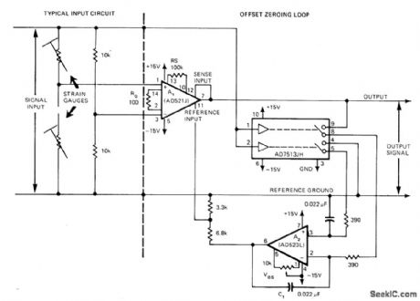
Simple offset zeroing loop reduces effective input offset of instrumentation amplifier to less than a microvolt by using zero-and-hold that nulls output of instrumentation opamp A1 to reference ground. Article describes operation in detail. Input signal source drives logic input, for nulling up to 4 V without using external nulling pot,.Typical input circuit using strain gages is shown at left of dashed line.-M. Cerat, Zeroing Loop Reduces Instrumentation Amplifier Offsets, EDN Magazine, March 20, 1976, p 100 and 102. (View)
View full Circuit Diagram | Comments | Reading(820)
LIGHT_CHASER_I
Published:2009/7/9 23:00:00 Author:May
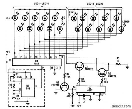
Up to 100 lights,LEDs,or optocoupler triac circuits can be sequentially activated by this circuit,One(U1)4017 decode counter sequences 10 LEDs whose common anode is returned through a second (U2) CD4017,which counts at one-tenth of the rate.The flash rate IS controlled by U3,a clock circuit,with a 555 timer. (View)
View full Circuit Diagram | Comments | Reading(3520)
THREE_WAY_TOUCH_LAMP
Published:2009/7/9 22:37:00 Author:May
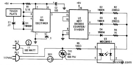
A three-way switch to control a lamp (off-dim-bright, etc.) uses an NE555 timer to generate a one-second pulse, triggered by ambient ac fields that are picked up by the human body. C1 and Dl form an input network. U2 is a decode counter/di ider and drives one of 10 outputs (three are used). The logic outputs drive various resistors in series with the LED in the optocoupler. The optocoupler controls a triac that is in series with a load (lamp, etc.).
By reconfiguring the outputs of U2, more than three brightness levels can be obtained, up to 10. An IN914 and resistor will be required for each output. (View)
View full Circuit Diagram | Comments | Reading(1461)
| Pages:41/72 At 204142434445464748495051525354555657585960Under 20 |
Circuit Categories
power supply circuit
Amplifier Circuit
Basic Circuit
LED and Light Circuit
Sensor Circuit
Signal Processing
Electrical Equipment Circuit
Control Circuit
Remote Control Circuit
A/D-D/A Converter Circuit
Audio Circuit
Measuring and Test Circuit
Communication Circuit
Computer-Related Circuit
555 Circuit
Automotive Circuit
Repairing Circuit