
LED and Light Circuit
Index 52
LED_FLASHER_USES_PUT
Published:2009/6/30 23:57:00 Author:May

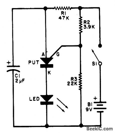
This flasher circuit operates as a relaxation oscillator with C1 discharged periodically through the LED as the PUT as the the put switches on. the flashing rate is about 100/minute with the component values listed. (View)
View full Circuit Diagram | Comments | Reading(1090)
ELECTRONIC_WAKE_UP_CALL
Published:2009/6/30 23:57:00 Author:May

A cadmium sulfide photocell (LDR1, which is a light-dependent resistor) is connected to the base and collector of an npn transistor, Q1. When light hits LDR1, the internal resistance goes from a very high (dark) value to a low (light) value, supplying base current to Q1, turning it on. The voltage across RI produces a bias that turns Q2 on, which in turn, supplies the positive voltage to U1 at pin 8 (the positive-supply input) and pin 4 (the reset input), to operate the 555 audio oscillator circuit. The circuit's sensitivity to light can be set via R6 (a 50,000 ohm potentiometer). R7 sets the audio tone to the most desirable sound. The squarewave audio tone is fed from U1 pin 3 to a small speaker through coupling capacitor C4 and current limiting resistor R4. (View)
View full Circuit Diagram | Comments | Reading(833)
AUTOMATIC_MOORING_LIGHT
Published:2009/6/30 23:55:00 Author:May
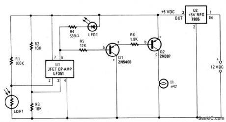
Integrated-circuit U1-an LF351 or 741 op amp-is used as a comparator to control the light. Resistors R2 and R3 provide a reference voltage of about 2.5 volts at pin 3 of U1. When daylight falls on light-dependent resistor LDR1, its resistance is low: about 1000 ohms. In darkness, the LDR's resistance rises to about 1 megohm. Since R1 is 100,000 ohms, and the LDR in daylight is 1000 ohms, the voltage ratio is 100 to 1; the voltage drop across the LDR is less than the 2.5 volt reference voltage and pin 2 of U1 is held at that voltage. In that state, the output at pin 6 of U1 is positive at about 4.5 volts, a value that reverse-biases Q1 to cutoff, which in turn holds Q2 in cutoff, thereby keeping lamp I1 off. When darkness falls, the LDR's resistance rises above R1's value and the voltage at pin 2 of U1 rises above the reference voltage of 2.5 volts. U1's output terminal (pin 6) falls to less than a volt and Q1 is biased on. The base-to-emitter current flow turns Q2 on, which causes current to flow through the lamp. When daylight arrives, the LDR's resistance falls sharply, which causes the lamp to be turned off, ready to repeat the next night/day cycle. (View)
View full Circuit Diagram | Comments | Reading(1020)
GAS_DISCHARGE_DISPLA
Published:2009/6/30 23:55:00 Author:May
National MM5309 digital clock glves choice of 12-or 24-h displayand 50-or 60-Hz operation for drving 4-digit gas-discharge display having colon and AM/PM indications. Separate cathode driver and sepa-rate anode driver are required for each digit.- MOS/LSI Databook, National Demiconductor, Santa Clara,CA,1977,p 1-2-1-8 (View)
View full Circuit Diagram | Comments | Reading(1814)
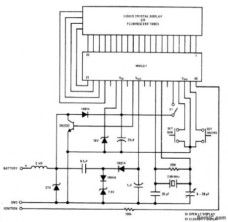
15_V_LCD
Published:2009/6/30 23:48:00 Author:May
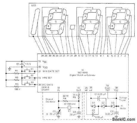
Will operate over 1 year on single 1.5-V AAA battery with accuracy of ±1 min. Basic timekeeping functions are provided by Motorola MC14440 CMOS device that includes calendar. 32.768-kHz NT-cut quartz crystal and trimming capacitor provide reference fre-quency. Output of 1.5-V alkaline cell is increased to 4 V for display by voltage tripler using MBD101 Schottky diodes.-J. Roy and A. Mou-ton, A Cordless, CMOS, Liquid-Crystal Display Clock, Motorola, Phoenix, AZ, 1977, EB-56. (View)
View full Circuit Diagram | Comments | Reading(1646)
SEQUENTIAL_AC_FLASHER
Published:2009/6/30 23:42:00 Author:May
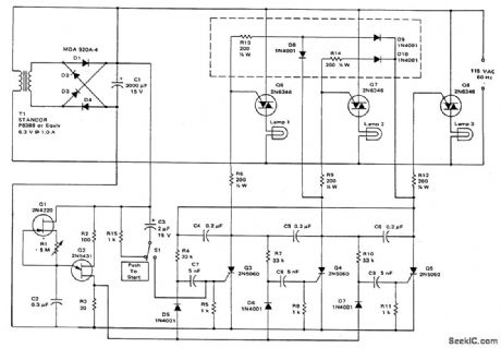
This circuit uses a ring counter made up of Q3, Q4 and Q5. Q2 acts as an oscillator which triggers the SCRs Q3, Q4 and Q5 in sequence. When an SCR fires, a 0.2μF ca-pacitor provides commutation, shutting off the previous stage. Triacs Q6, Q7 and Q8 control lamps 1, 2 and 3 respectively. (View)
View full Circuit Diagram | Comments | Reading(0)
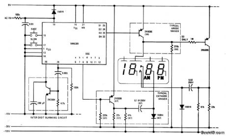
6_DIGIT_LED_WITH_SLEW_BUTTONS
Published:2009/6/30 23:39:00 Author:May
National MM5313 PM05 digital clock IC drives display which includes four discrete LEDs mounted on readout panel to form colons between hours, minutes, and seconds. AC supply provides 14 VDC for IC and 7 VDC for displays. Hold push-button SWt stops count to give precise seconds setting. Slow-slew button SW2 advances time at 1 min/s for precise setting, and fast-slew but-ton SW3 advances time 1 h/s. Digit drivers Q1-Q12 are Darlington-connected pairs of PNPtran-sistors. Segment drivers Q13-Q19 are single PNP transistors.-M. S. Robbins, Electronic Clocks and Watches, Howard W. Sams, Indi-anapolis, IN, 1975, p 103 and 113. (View)
View full Circuit Diagram | Comments | Reading(1065)
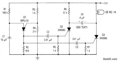
TRANSISTORIZED_FLASHERS
Published:2009/6/30 23:38:00 Author:May
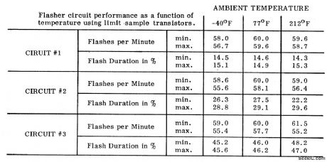
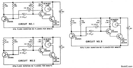
Transistors Q1 and Q2 are connected as a free running multivibrator. The output, at the emitter of Q2, drives the base of the common emitter amplifier Q3, which controls the lamp. This circuit configuration permits the flash duration, the interval between flashes, and the lamp type to be varied independently. Flash duration is proportional to the prod-uct of R2C2 while the off interval is proportional to the product of R3C1. Consequently, when the flash timing must be accurately maintained, these component tolerances will have to be held to similar limits.All three circuits described are designed for barricade warning flasher lights such as used in highway construction. They differ only in flash duration which normally is 15%, 25%; or 50% of the flash rate. Performance has been checked at ambient temperatures of -40'F, 77'F, and 212°F. A GE 5 volt, 90 milliampere type No. 1850 lamp is used. (View)
View full Circuit Diagram | Comments | Reading(962)
1_KW_FLIP_FLOP_FLASHER_CIRCUIT
Published:2009/6/30 23:27:00 Author:May

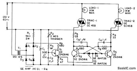
This is an application of the static switch circuit where the control logic is a flip-flop which is controlled by the unijunction transistor. The flashing rate can be adjusted from about 0.1 second to a 10 second cycle time. (View)
View full Circuit Diagram | Comments | Reading(870)
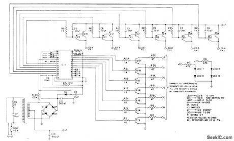
LED_SYNCHROSCOPE
Published:2009/6/30 23:17:00 Author:May
Circuit uses four LEDs to indicate direction of phase error as correct setting is approached when tuning oscillator to standard frequency. Lamps form display that rotates once per cycle at reference frequency, with brightness of each lamp being modulated at frequency of oscillator being adjusted. Dis-play thus appears to have frequency equal to difference between two signal frequencies, ro-tating in direction indicative of sense of fre-quency difference. Mount lamps on smallest possible circle. Diode and LED types are not crit-ical.-R. H. Pearson, An L.E.D. Synchroscope, Wireless World, Sept. 1974, p 321. (View)
View full Circuit Diagram | Comments | Reading(2725)
SEQUENTIAL_FLASHER
Published:2009/6/30 23:17:00 Author:May
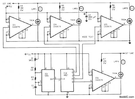
A 555 timer, IC1, drives a 4017 CM0S decade counter. Each of the 4017's first four outputs drives a CA3079 zero-voltage switch. Pin 9 of the CA3079 is used to inhibit output from pin 4, thereby disabling the string of pulses that IC normally delivers. Those pulses occur every 8,3 ms, i.e., at a rate of 120 Hz. Each pulse has a width of 120 μs.Due to the action of the CA3079, the lamps connected to the TRI-AC's turn on and off near the zero crossing of the ac waveform. Switching at that point increases lamp life by reducing the inrush of current that would happen if the lamp were turned on near the high point of the ac waveform. In addition, switching at the zero crossing reduces Radio-Frequency Interference (RFI) considerably.CAUTION: The CA3079's are driven directly from the 117-volt ac power line, so use care. (View)
View full Circuit Diagram | Comments | Reading(0)
LED_FLASHER_USES_UJT
Published:2009/6/30 23:11:00 Author:May


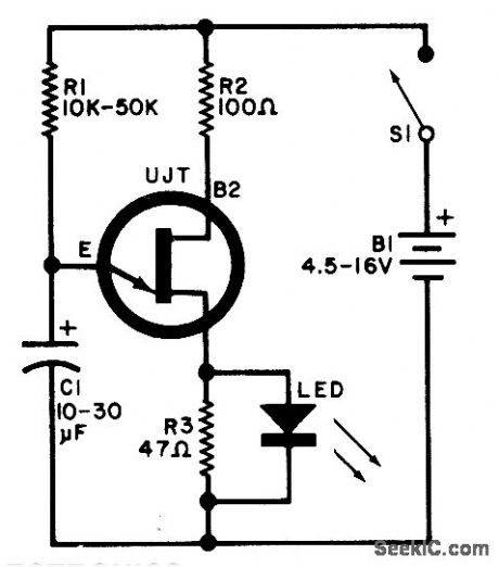
A relaxation oscillator is used to flash an LED in the base circuit. C1 is charged slowly through R1 by the power source, then discharged periodically through R3 and the LED by the UJT. Flashing rate is determined by the supply voltage and by R1-C1's time constant.UJT = 2N4871 (View)
View full Circuit Diagram | Comments | Reading(2287)
SCR_RELAXATION_FLASHER
Published:2009/6/30 22:58:00 Author:May
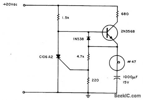

Flashing occurs each time the capacitor discharges through the tumed-on SCR. When the discharge current falls below the SCR holding current, the SCR turns off, and the capacitor begins charging for another cycle. The circuit will maintain a slower but good flashing capability even after considerable battery degradation. (View)
View full Circuit Diagram | Comments | Reading(1255)
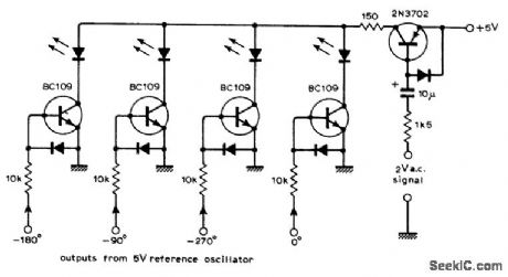
BEAT_FREQUENCY_DISPLAY
Published:2009/6/30 22:55:00 Author:May
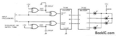
Apparent rotation of dot on four-LED display gives indication of beat frequency between ttnro tone oscillators.When F1 is greater than F2, dot rotates clockwise. When F1 is less than F2, dot rotates coun torclockwise. When F1 equals F2, dot does not move.-Circuits, 73Magazine, July 1977, p 35. (View)
View full Circuit Diagram | Comments | Reading(898)
TIDE_CLOCK
Published:2009/6/30 22:46:00 Author:May
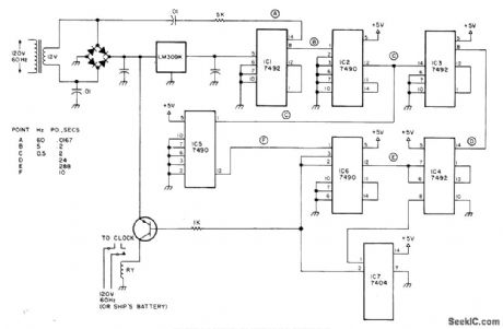
Circuit shuts off electric clock of any type for 5 s out of every 144 s, to give loss of 50 min in 24 h as required for making high tides conform to clock readings. Regulated 5-V supply shown drives TTL 7492 frequency divider that reduces 60-Hz line frequency by factor of 12 to 5 Hz. 7490 divides this by 10 to give 0.5 Hz.Two more 7492s divide by 12 and 12 to give symmetrical pulses with period of 288s. Second 7490 divides 2-s pulse down to 10 s. Counter IC4 inhibits 5-s counter by feeding low output into one gate of IC7 hex inverter. When IC4 counts up to 144 s, its output goes high and resets IC6 to low for start of 5-s low period of that counter.Article gives timing waveforms. Switching tran-sistor is used to control relay that opens clock circuit. Set tide clock at 12:00 for high tide at location of use .and t will be 12:00 at high tide thereafter.Low tide will then be at 6:00.-J.F.Crowhter Time and -Digitally,73 magazine,Aug.1978,p 156-157 (View)
View full Circuit Diagram | Comments | Reading(1563)
ELECTRONIC_LIGHT_FLASHER
Published:2009/6/30 22:44:00 Author:May
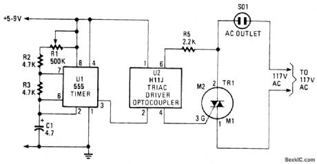
The blinking or flashing rate is determined by U1, a 555 timer integrated circuit. Its output, at pin 3, feeds U2, a HIIJ triac driver. That driver consists of an infrared LED that is coupled internally to a light-activated silicon bilateral switch (DIAC). When the LED internal to U2 is turned on by the timer, U1, its light triggers the DIAC; effectively closing the circuit between pins 4 and 6, and fires the Triac, TRI through its gate circuit. When the Triac is firing, it acts as a closed circuit that turns on the light (or other device it may be controlling via 501). When the timer turns off, the LED, the DIAC and Triac stop conducting and the light turns off. The sequence then repeats. The flashing rate can be varied by means of R1, a 500,000 ohm potentiometer. (View)
View full Circuit Diagram | Comments | Reading(3711)
ALTERNATING_FLASHER
Published:2009/6/30 22:39:00 Author:May

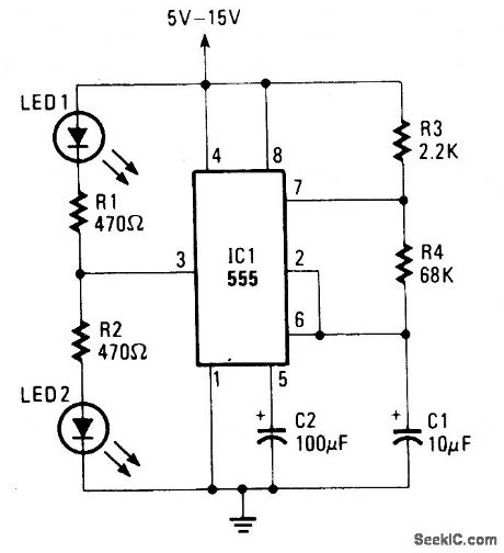
The LED's flash alternately.The flash rate is determined by C1 and R4. (View)
View full Circuit Diagram | Comments | Reading(2116)
LCD_WRISTWATCH
Published:2009/6/30 22:38:00 Author:May
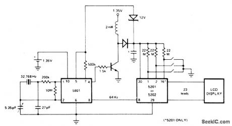
Inverter section of Intel 5801 oscillator/divider is used with 32,768-Hz crystal to produce time base. First divider in 5801 reduces this to 1024 Hz for driving upcon-verter transistor. Feedback from transistor through 12-V zener is used to regulate and con-trol pulse width of 1024-Hz signal. Upconverter also provides 12-15 V required by LCD and 5201 decoder/driver IC. Output to each LCD segment and to common backplate is 32-Hz square wave.Separate drive flashes colon at 1-Hz rate.-M. S. Robbins, Electronic Clocks and Watches, Howard W, Sams, Indianapolis, IN, 1975, p 128-130. (View)
View full Circuit Diagram | Comments | Reading(1405)
LOW_VOLTAGE_LAMP_FLASHER
Published:2009/6/30 22:32:00 Author:May
The circuit is composed of a relaxation oscillator formed by Q1 and an SCR flip-flop formed by Q2 and Q3. With the supply voltage applied to the circuit, the timing capacitor C1 charges to the firing point of the PUT, 2 volts plus a diode drop. The output of the PUT is coupled through two 0.02 μF capacitors to the gate of Q2 and Q3. To clarify operation, assume that Q3 is on and capacitor C4 is charged plus to minus as shown in the figure. The next pulse from the PUT oscillator turns Q2 on. This places the volt-age on C4 across Q3 which momentarily reverse biases Q3. This reverse voltage turns Q3 off. After discharging, C4 then charges with its polarity reversed to that shown. The next pulse from Q1 turns Q3 on and Q2 off. Note that C4 is a non-polarized capacitor. For the component values shown, the lamp is on for about 1/2 second and off the same amount of time. (View)
View full Circuit Diagram | Comments | Reading(858)
CLIPPING_POINT_INDICATOR
Published:2009/6/30 21:21:00 Author:May
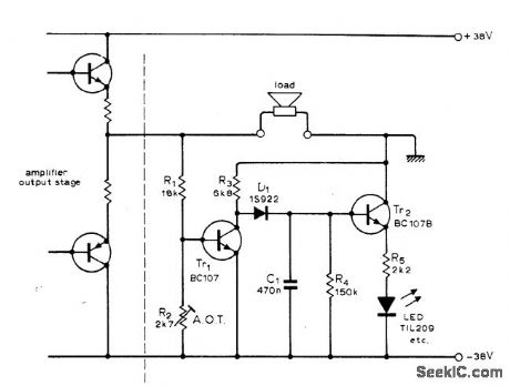
Uses LED to indicate when clipping distortion begins in 50-W power amplifier. Display circuit is referenced to negative supply, making detection level Indopendent of supply variation; circuit thus works equally well for instantaneous, music, or continuous overloads. Tr1 is normally turned hard on and Tr2 is off. When overload makes collector-emitter voltage of lower amplifier output transistor approach saturation, Tr, begins to turn off and @, charges through D, so LED turns on. Attack time is chosen to make single 3-ms overload transient visible.-J. Dawson and K Northover, L.E.D. Clip Indicator, Wireless World, Jan. 1976, p 60. (View)
View full Circuit Diagram | Comments | Reading(2134)
| Pages:52/72 At 204142434445464748495051525354555657585960Under 20 |
Circuit Categories
power supply circuit
Amplifier Circuit
Basic Circuit
LED and Light Circuit
Sensor Circuit
Signal Processing
Electrical Equipment Circuit
Control Circuit
Remote Control Circuit
A/D-D/A Converter Circuit
Audio Circuit
Measuring and Test Circuit
Communication Circuit
Computer-Related Circuit
555 Circuit
Automotive Circuit
Repairing Circuit