
LED and Light Circuit
Index 54
LEVEL_CROSSING_DlSPLAY
Published:2009/6/29 1:38:00 Author:May
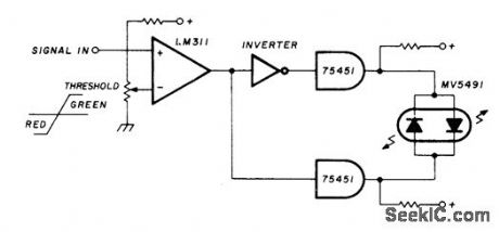
Uses Monsanto MV5491 dual red/green LED, with 220 ohms in upper lead to +5 V supply and 100 ohms in lower +5 V lead because red and green LEDs in parallel back-to-back have different voltage re quirements. Circuit requires SN75451 driver ICs and one section of SN7404 hex inverter, with LM311 comparator. All operate from single +5 V source. Provides indicator change from red to green with input change of only a few millivolts.—K. Powell, Novel Indicator Circuit, Ham Radio, April 1977, p 60-63. (View)
View full Circuit Diagram | Comments | Reading(764)
Electronic hygienical small night lights
Published:2011/8/1 3:05:00 Author:Ecco | Keyword: Electronic, hygienical , small, night lights

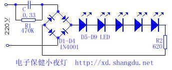
The internal wiring of the lamp is shown as the chart. The 220V mains supply is bucked by capacitor C, rectified by diodes D1-D4 to provide the supply for light emitting diodes D5-D9. LEDs should use green light because green can make people quiet, relaxing. Electronic hygienical small night lights have soft lighting, which is like moon lighting to create a warm and hazy light environment, and it helps people to calm down and fall asleep. In the summer nights, the night light can also give a quiet, cool visual experience.
(View)
View full Circuit Diagram | Comments | Reading(1198)
The light dependent tube detection circuit
Published:2011/7/21 2:49:00 Author:Seven | Keyword: light dependent tube, detection circuit
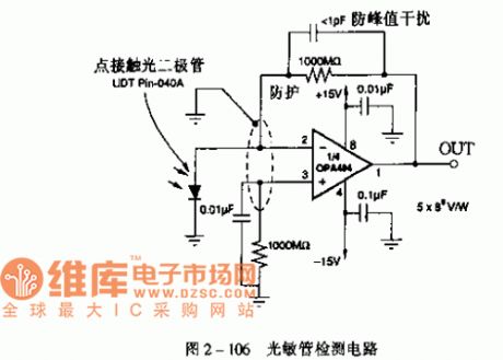
The high-speed isolator computing amplifier circuit of sensor OPA404
Function: used in photoelectric detection, medical devices, sonar and ultra-sonic detection and other areas.
(View)
View full Circuit Diagram | Comments | Reading(582)
The light detection single power source circuit
Published:2011/7/21 2:53:00 Author:Seven | Keyword: single power source
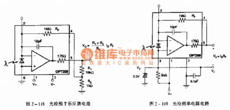
The light sensor OPT209 LED computing amplifier integrated circuit Functions: used in positioning and approaching sensors, fog detection, photo analysis and medical devices, etc.
(View)
View full Circuit Diagram | Comments | Reading(737)
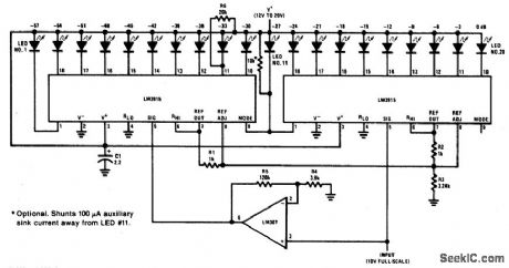
OIL_PRESSURE_DISPLAY
Published:2009/6/28 22:37:00 Author:May
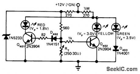
Bed, yellow, and green LEDs give positive indication of oil pressure levelon electronic gage console developed for motorcycle. Transducer converts oil pres-sure to variable resistance RT, which in turn varies bias on transistors. LEDs have different forward voltages at which they light, so proper selection of bias resistors ensures that only one LED is on at a time to give desired indication of oil pressure.-J. D. Wiley, Instrument Console Features Digital Displays and Built-In Combo Lock, EDN Magazine, Aug, 5, 1975, p 38-43. (View)
View full Circuit Diagram | Comments | Reading(752)
RF_OUTPUT_INDICATOR
Published:2009/6/28 22:32:00 Author:May
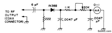
Designed for use with amateur radio transmitters Pot is adjusted for maximum desired indication on band usedFor 20-10 meters、6-pF capacitoris adequateOn lower bands (80-40 meters), use 7 or 12 pF instead.-Novice Q & A 73 Magazine, Holiday issue 1976, p 20. (View)
View full Circuit Diagram | Comments | Reading(1975)
10_MHz_UNIVERSAL_COUNTER
Published:2009/6/28 21:48:00 Author:May
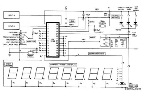


Circuit NotesThis is a minimum component complete Universal Counter. It can use input frequencies up to 10 MHz at INPUT A and 2 MHz at INPUT B. If the signal at INPUT A has a very low duty cycle, it may be necessary to use a 74121 monostable multivibrator or similar circuit to stretch the input pulse width to be able to guarantee that it is at least 50 ns in duration. (View)
View full Circuit Diagram | Comments | Reading(3523)
EXCLAMATION_POINT_DISPLAY
Published:2009/6/28 21:34:00 Author:May
View full Circuit Diagram | Comments | Reading(713)
12_HOUR_CLOCK_WITH_GAS_DISCHARGE_DISPLAYS
Published:2009/6/28 21:26:00 Author:May

View full Circuit Diagram | Comments | Reading(1002)
60_dB_DOT_MODE_DISPLAY
Published:2009/6/28 21:20:00 Author:May
View full Circuit Diagram | Comments | Reading(884)
TELEPHONE_OFF_HOOk_INDICATOR
Published:2009/6/25 22:27:00 Author:May
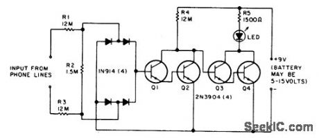
The LED flickers when the phone is ringing or being dialed. It glows steadily when the phone is off the hook. (View)
View full Circuit Diagram | Comments | Reading(1493)
VISUAL_MODULATION_INDICATOR
Published:2009/6/25 21:45:00 Author:May
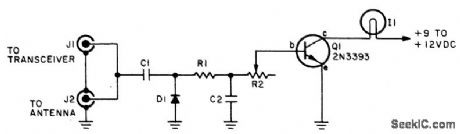
Indicator lamp brightness varies in step with modulated RF signal. Adjust R2 with transmitter on (modulated) until the lamp flashes in step with modulation. C1 = 5 pf, C2 = 100 pF, D1 = 1N60 or 1N34 (Germanium), R3 = 10 K pot, I1 = 6-8 V, 30-60 mA incandes-cent bulb, Q1 = 2N3393 (for increased sensitivity use 2N3392 or other high-gain transistor). (View)
View full Circuit Diagram | Comments | Reading(993)
AUDIO_CONTROLLED_LAMP
Published:2009/6/25 21:17:00 Author:May
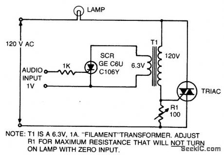
This is an on-off control with isolated, low voltage input. Since the switching action is very rapid, compared with the response time of the lamp and the response of the eye, the effect produced with audio input is similar to a pro-portional control circuit. If the input signal to the SCR consists of phase-controlled pulses, full wave control of the lamp load is obtained. (View)
View full Circuit Diagram | Comments | Reading(815)
PEAK_LEVEL_INDICATOR
Published:2009/6/25 20:49:00 Author:May
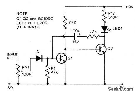
The LED is normally lit, but it will be briefly extinguished if the input exceeds a preset (by RV1) level. A possible application is to monitor the output voltage across a loudspeaker; the LED will flicker with large signals. (View)
View full Circuit Diagram | Comments | Reading(2799)
CMOS_LOGIC_PROBE
Published:2009/6/25 4:07:00 Author:Jessie

The logic probe can indicate four input states, as follows: floating input-all LEDs off; logic 0 input-D2 switched on (D3 will briefly flash on); logic 1 input-Dl switched on; pulsing input-D3 switched on, or pulsing in the case of a low frequency input signal (one or both of the other indicators will switch on, showing if one input state predominates). (View)
View full Circuit Diagram | Comments | Reading(0)
LOGIC_PROBE_YIELDS_THREE_DISCRETE_STATES
Published:2009/6/25 4:02:00 Author:Jessie
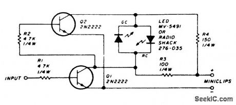
The circuit uses a dual LED. When power is applied to the probe through the power leads, and the input is touched to a low level or ground, Q1 is cut off. This will cause Q2 to conduct since the base is positive with respect to the emitter. With Q1 cut off and Q2 con-ducting, the greendiode ofthe dual LED will be forward biased, yielding a green output.Touching the probe tip to a high level will cause Q1 and Q2 to complement, and the red diode will be forward biased, yielding a red output from the LED. An alternating signal will cause alternating conduction of the red and green diodes and willyield an indication approxi-mately amber. In this manner, both static and dynamic signals can be traced with the logic probe. (View)
View full Circuit Diagram | Comments | Reading(1532)
EMERGENCY_LIGHT
Published:2009/6/25 2:08:00 Author:May
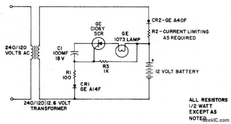
This simple circuit provides battery operated emergency lighting instantaneously upon failure of the regular ac service. When line power is restored, the emergency light turns off and the battery recharges automatically; The circuit is ideal for use in elevator cars, corridors and similar places where loss of light due to power failure would be undesirable.Completely static in operation, the circuit requires no maintenance. With ac power on, capacitor C1 charges through rectifier CR1 and resistor RI to develop a negative voltage at the gate of the C106Y SCR. By this means, the SCR is prevented from being triggered, and the emergency light stays off. At the same time, the battery is kept fully charged by rectifier CR2 and resistor R2. Should the ac power fail, C1 discharges and the SCR is triggered on by battery power through resistor R3. The SCR then energizes the emergency light. Reset is automatic when ac is restored, because the peak ac line voltage biases the SCR and turns it off. (View)
View full Circuit Diagram | Comments | Reading(9586)
LOW_COST_LAMP_DIMMER
Published:2009/6/25 1:59:00 Author:May
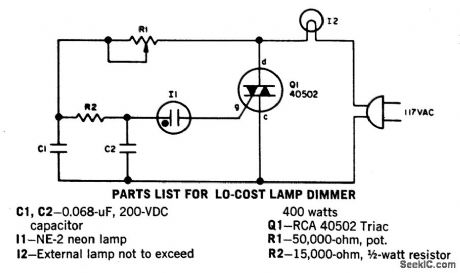
Without a heatsink, Triac Q1 handles up to a 400-watt lamp. The neon lamp does not trip the gate until it conducts so the lamp turns on a medium brilliance. The lamp can then be backed off to a soft glow. (View)
View full Circuit Diagram | Comments | Reading(2601)
800_W_SOFT_START_LIGHT_DIMMER
Published:2009/6/25 1:58:00 Author:May

View full Circuit Diagram | Comments | Reading(2433)
800_W_TRIAC_LIGHT_DIMMER
Published:2009/6/25 1:50:00 Author:May


View full Circuit Diagram | Comments | Reading(814)
| Pages:54/72 At 204142434445464748495051525354555657585960Under 20 |
Circuit Categories
power supply circuit
Amplifier Circuit
Basic Circuit
LED and Light Circuit
Sensor Circuit
Signal Processing
Electrical Equipment Circuit
Control Circuit
Remote Control Circuit
A/D-D/A Converter Circuit
Audio Circuit
Measuring and Test Circuit
Communication Circuit
Computer-Related Circuit
555 Circuit
Automotive Circuit
Repairing Circuit