
LED and Light Circuit
Index 47
TWO_VARIABLE_LED_MATRIX_DISPLAY
Published:2009/7/6 3:51:00 Author:May
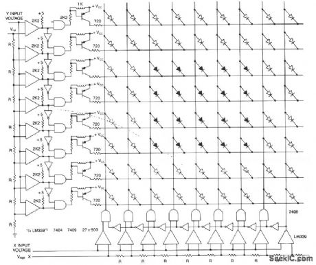
This matrix can show the values of two variables, for example, frequency and voltage. The display is a graph made from a matrix of LEDs. The LEDs on each axis are color coded, red for out of tolerance and green for in, forming a red band around the inner green rectangle. The two input voltages proportional to the functions being measured are presented to the two columns of comparators. The other comparator input is a reference voltage derived from resistor ladder R1 to RX. The output of each row of comparators is processed with an inverted and an AND gate to allow only one active output for any input value. The LED at the intersection of the active drives shows the relationship of the two inputs. The advantage of this display is the ease in reading, modification, and also its small size. All comparators are LM339 quads. (View)
View full Circuit Diagram | Comments | Reading(1953)
FLASHING_THIRD_BRAKE_LIGHT
Published:2009/7/6 3:46:00 Author:May
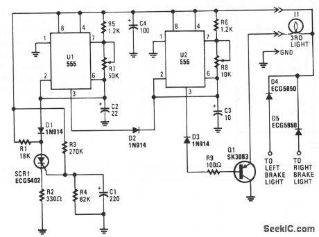
When power is first applied, three things happen: light-driving transistor Q1 is switched on due to a low output from U2 pin 3; timer U1 begins its tinting cycle, with the output, pin 3, becoming high, inhibiting U2's trigger, pin 2, via D2; and charge current begins to move through R3 and R4 to C1.
When U1's output becomes low, the inhibiting bias on U2 pin 2 is removed, so U2 begins to oscillate, flashing the third light via Q1, at a rate determined by R8, R6, and C3. That oscillation continues until the gate-threshold voltage of SCR1 is reached, causing it to fire and pull U1's trigger, pin 2,low.
With its trigger low, U1's output is forced high, disabling U2's triggering. With triggering inhibited, U2's output switches to a low state, which makes Q1 conduct, turning on I1 until the brakes are released.Of course, removing power from the circuit resets SCR1, but the rc network consisting of R4 and C1 will not discharge immediately and will trigger SCR1 earlier. So, frequent brake use means fewer flashes.
(View)
View full Circuit Diagram | Comments | Reading(1137)
DELAYED_EXTRA_BRAKE_LIGHT
Published:2009/7/6 2:26:00 Author:May
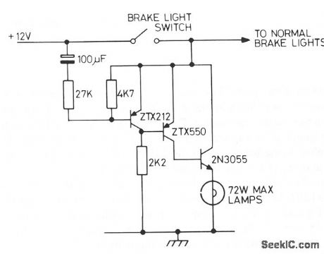
Operating the brake pedal of the car brings on the normal brake lights and then, after a delay, the extra lights are tumed on. A bimetal strip in series with the the lights would make them flash. (View)
View full Circuit Diagram | Comments | Reading(985)
MULTIPLEXED_DISPLAY
Published:2009/7/6 2:19:00 Author:May
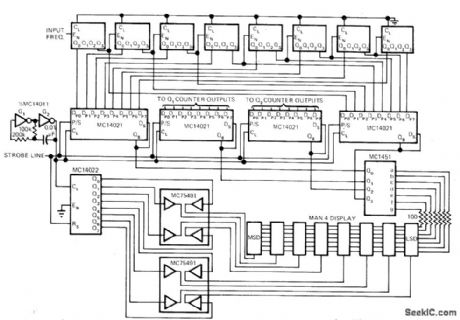
Used with battery-operated frequency Gaunter to reduce battery drain by multiplexing single decoder driver between all of MAN-4 displays, Readout is integrated by eye over total time period, making display appear continuous. Display operates at peak of 20 mA but duty cycle is only 12.5%.Counter is operated from 6-V supply. Four MC14021 8-bit shift registers implement multiplexing and provide latches needed to store count from MC14518 counter chain. Article describes operation in detail and gives circuit of companion front end and 5-MHz counter.-D.Aldridge, CMOS Counter Circuitry Slashes Battery Power Requirements, EDN Magazine, Oct. 20, 1974, p 65-71.
(View)
View full Circuit Diagram | Comments | Reading(1925)
PLL_LOST_LOCK_INDICATOR
Published:2009/7/6 1:11:00 Author:May
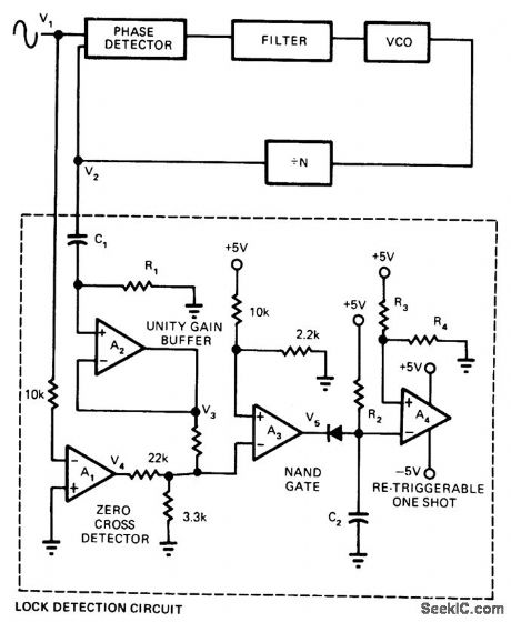
Developed for use with phase-locked loop to indicate both acquisition and loss of lock. Based on concept that lock exists as long as static-phase error is less than 90°. Uses quad opamp package such as RC4136, with A4 feeding retriggerable one-shot; output of one-shot is low when lock exists. When lock is lost, output of one-shot immediately goes high and remains high until lock is reacquired plus time duration of one-shot. Developed for use in systems where certain processes must be interrupted immediately upon loss of lock.-J. C. Hanisko, PLL Lock Indicator Uses a Single IC, EDN Magazine, Oct. 5, 1976, p 104. (View)
View full Circuit Diagram | Comments | Reading(1118)
AUTO_BREAKDOWN_FLASHER
Published:2009/7/5 23:55:00 Author:May
Two-transistor amplifer with regenerative feedback sends 60-ms pulses of currents up to several amperes through low-voltage lamp to give high-brilliance flashes without destroying lamp. L1 can be PR-2 lamp (Radio Shack 272-1120).-F. M.Mims, Transistor Projects, Vol. 1, Radio Shack, Fort Worth, LX, 1977, 2nd Ed., p 27-32.
(View)
View full Circuit Diagram | Comments | Reading(835)
KEYBOARD_ENTRY_WITH_4_1_2_DIGIT_DISPLAY
Published:2009/7/5 23:44:00 Author:May
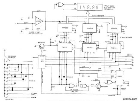
Developed to give keyboard entry of desired frequency for 2-meter frequency as alternative to thumbwhee-switch setting of frequenoy, When key is depressed, mono (one shot) fires, causing CD4022 counter to incre, ment. At same time, keyswitch places appropriate BCD data on input Iines of 74C192 presettable decade counters, Output from counters goes to synthesizer input and to display decoder/driver. LED display may be used in place of LCD display if current drain is not important, Keyboard lockout switch prevents acidental change of gyequency.-M. l. Cohen, A Practical 2m Synthesizer, 73 Magazine, Sept.1977, p n46-151. (View)
View full Circuit Diagram | Comments | Reading(2807)
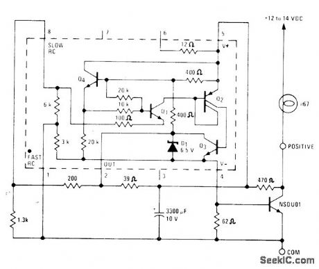
6_V_OR_15_V_INDICATOR
Published:2009/7/5 23:26:00 Author:May
Uses DigiKey LM3909N flasher/oscillator to drive LED at 2 Hz as ON/OFF indicator for battery-operated devices. For 6-V battery, CT is 400 μF, Rs is 1000 ohms, and RFB is 1500 ohms. For 15 V, coffe-sponding values are 180, 3900, and 1000. Battery life is essentially same as shelf life.-C.Shaw, ON-OFF Indicator for Battery Device,QST, March 1978, p 41-42. (View)
View full Circuit Diagram | Comments | Reading(971)
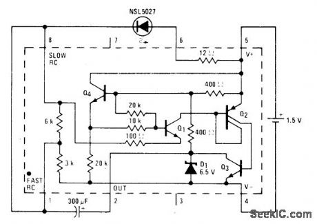
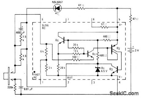
2_kHz_FLASHER_FOR_LED
Published:2009/7/5 23:24:00 Author:May

Single 1.5-V cell provides power for National LM3909 flasher IC that operates at high enough frequencyto appear on continuously, for use as indicator in battery portable equipment. Duty cycle and frequency of current pulses to LED are increased by changing external resistors until average energy reaching LED provides sufficient light for application. At 2 kHz, no flicker is noticeable.-P. Lefferts, Power-Miser Flasher IC Has Many Novel Applications, EDN Magazine, March 20, 1976, p 59-66. (View)
View full Circuit Diagram | Comments | Reading(757)
LED_FLASHER
Published:2009/7/5 23:23:00 Author:May
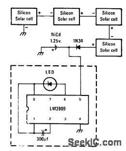
Requires only LM3909 IC and external capacitor operating from 1.25-V nicad or other penlight cell. Circuit can be duplicated for as many additional flashing LEDs as are desired for display. Optional charging circuit uses silicon solar cells and diode for daytime charging of battery automatically.-J. A. Sandier, 11 Projects under $11, Modern Electronics, June 1978,p54-58. (View)
View full Circuit Diagram | Comments | Reading(0)
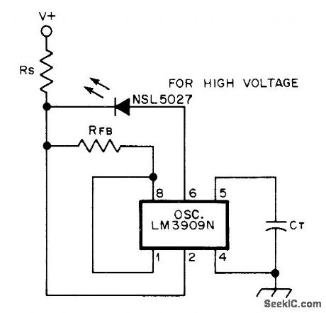
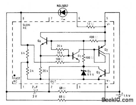
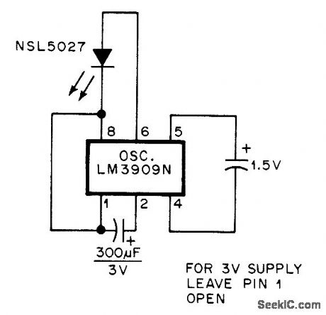
15_V_LED_FLASHER
Published:2009/7/5 23:22:00 Author:May
National LM3909 IC operating from 1.5-V battery drives NSL5027 LED in such a way that current is drawn by LED only about 1% of time. External 300-μF capacitor sets flash rate at about 1 Hz.- Linear Applications,Vol.2, National Semiconductor,Santa Clara, CA, 1976, AN-154, p 2. (View)
View full Circuit Diagram | Comments | Reading(1365)
COMPARATOR_LED_FLASHER
Published:2009/7/5 23:20:00 Author:May
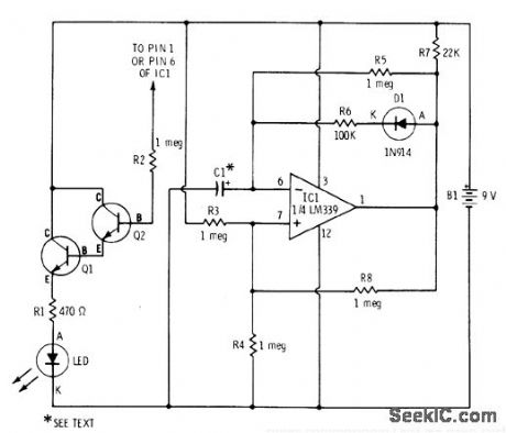
One section of LM339 quad comparator drives two RS2016 NPN transistors having LED load, to give simple flasher for classroom demonstrations. Circuit can be duplicated with other three sections to give four flashers. Connecting R2 to pin 1 of IC gives conventional ON/OFF flash cycle in which LED tums on and off rapidly. Connecting R2 to pin 6 makes LED tum on rapidly and tum off very slowly. C1 controls flash interval; typical value is 0.01 μF.-F. M. Mims, Integrated Circuit Projects, Vol. 5, Radio Shack, Fort Worth, TX, 1977, 2nd Ed., p 45-51. (View)
View full Circuit Diagram | Comments | Reading(1250)
RED_GREEN_LED_FLASHER
Published:2009/7/5 23:18:00 Author:May
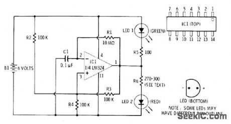
One section of LM324 quad opamp is connected as squarewave generator giving about 1 flash per second for each LED. Series resistors for LEDs have different values because they have different forward voltage requirements. If LED 2 glows between flashes, increase value of R6 slightly. Too large a value for R6 reduces flash brilliance of LED 2. Supply can be 5 or 6 V.-F. M. Mims, Semiconductor Projects, Vol. 1, Radio Shack, Fort Worth, TX, 1975, p 69-74.
(View)
View full Circuit Diagram | Comments | Reading(1688)
LED_BLINKER
Published:2009/7/5 23:18:00 Author:May

Two sections of SN7400 quad gate form MVBR operating at low enough frequency so LED status indicators come on and off slowly for visual observation of MVBR. LEDs are optional and do not affect operation of MVBR. Capacitors must be same value. Ideal for student demonstration in classroom or as Science Fair exhibit.-A. MacLean, How Do You Use ICs?, 73 Magazine, Dec.1977, p 56-59.
(View)
View full Circuit Diagram | Comments | Reading(1219)
15_V_OR_3_V_INDICATOR
Published:2009/7/5 23:15:00 Author:May
Digi-Key LM3909N flasher/oscillator drives LED serving as ON/OFF indicator for battery-operated devices. At flash rate of 2 Hz, battery life almost equals shelf life.-C, Shaw, ON-OFF Indicator for Battery Device, QST, March 1978, p 41-42. (View)
View full Circuit Diagram | Comments | Reading(2401)
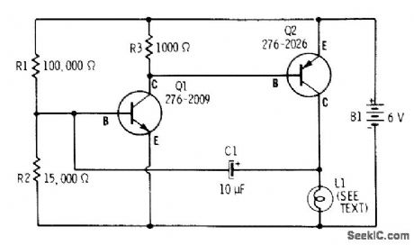
ALARM_DRIVEN_FLASHER
Published:2009/7/5 23:13:00 Author:May
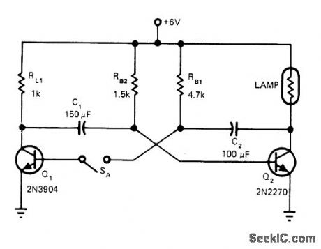
Simple two-transistor flasher circuit for annunciator system is activated by alarm. Operator acknowledges alarm condition by depressing SA, which changes lamp from flashing to steady ON condition. 6-V incandescent lamp draws about 0.3 A through Q2, but 1K load resistor for Q1 limits current of this transistor to about 6 mA so smaller transistor can be used.-T. Stehney, Flasher Design Cuts Extra Components, EDN Magazine, Sept. 20, 1978, p 144. (View)
View full Circuit Diagram | Comments | Reading(1159)
SINGLE_FLASH_LED
Published:2009/7/5 23:10:00 Author:May
Mono MVBR connection of National LM3909 IC produces 0.5-s flash with LED each time pushbutton makes momentary contact.- Linear Applications, Vol. 2, National Semiconductor, Santa Clara, CA, 1970, AN-154,p 9.
(View)
View full Circuit Diagram | Comments | Reading(932)
SCR_FLASFIES_LED
Published:2009/7/5 23:08:00 Author:May
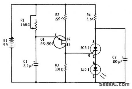
UJT oscillator Q1 provides timing pulses for triggering SCR driving red Radio Shack 276-041 LED. Circuit draws only 2 mAfrom 9-V battery when producing 12 flashes per second. SCR is 6-A 50-V 276-1089.-F. M. Mims, Semiconductor Proiects, Vol.2, Radio Shack, Fort Worth, TX, 1976, p 78-84. (View)
View full Circuit Diagram | Comments | Reading(1020)
1_Hz_AUTO_FLASHER
Published:2009/7/5 23:03:00 Author:May


Lamp drawing nominal 600 mA is flashed at 1 Hz by National LM3909 flasher IC operating from 12-V automotive batterv. Use of 3300-μF capacitor makes flasher IC immune to supply spikes and provides means of limiting IC supply voltage to about 7 V.-P.Lefferts, Power-Miser Flasher IC Has Many Novel Applieations, EDN Magazine, March 20, 1976, p 59-66.
(View)
View full Circuit Diagram | Comments | Reading(1065)
CLOCK_DRIVE_FOR_FLIP_FLOP_FLASHER
Published:2009/7/5 22:58:00 Author:May

555 timer connected as astable VBR generates series of timing pulses at rate determinod by value of capacitor and settifig of 1-megohm pot Provides automatic string of input pulses for driving flip-flop of dual flasher,Pulse output oestoinput capacitor C1 offlip-flop,-F.M.Mims, Integrated Circuit ,vol,5, Radio Shack,Fort Worth,TX,1977,2nd Ed,p 30-37. (View)
View full Circuit Diagram | Comments | Reading(752)
| Pages:47/72 At 204142434445464748495051525354555657585960Under 20 |
Circuit Categories
power supply circuit
Amplifier Circuit
Basic Circuit
LED and Light Circuit
Sensor Circuit
Signal Processing
Electrical Equipment Circuit
Control Circuit
Remote Control Circuit
A/D-D/A Converter Circuit
Audio Circuit
Measuring and Test Circuit
Communication Circuit
Computer-Related Circuit
555 Circuit
Automotive Circuit
Repairing Circuit