
LED and Light Circuit
Index 51
MULTIPLEXED_CLOCK_DlSPLAY
Published:2009/7/1 2:08:00 Author:May
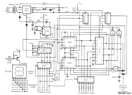
Multiplexed display suitable for LED readouts is provided by circuit using TTL counters to count 60-Hz Iine.When count reaches 10 o'clock, flip-flop M is set on evely cycle. Gate G3 then detects when time goes to 13 o'clock, and clears shift register.Carry flip-flop remains set, so 1 is loaded into hours digit to accomplish transition from 12:59:59 to 1:00:00. Seven-segment decoder driver Iooks at shift register output and drives segment lines of LED Leading hours digit is blanked,using RBI input on 9317.-G.Smith,Novel clock Circuit Provides Multiplexed Display,EDN Magazine.Sept 1,1972,p 50-51.
(View)
View full Circuit Diagram | Comments | Reading(2671)
LINEAR_VARIABLE_DIFFERENTIAL_TRANSFORMER_SIGNAL_CONDITIONER
Published:2009/7/1 2:05:00 Author:May
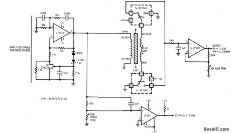
A1 and its associated components furnish an amplitude stable she wave source. A1's positive feedback path is a Wein bridge, tuned for 1.5 kHz, Q1, the LT1004 reference, and additional components in Al's negative loop unity-gain stabilize the amplifier. A1's output an amplitude stable sine wave, drives the LVDT. C1 detects zero crossings and feeds the LTC1043 clock pin. A speed-up network at C1's input compensates LVDT phase shift, synchronizing the LTC1043's clock to the transformer's output zero crossings. The LTC1043 alternately connects each end of the transformer to ground, resulting in positive half-wave rectification at pins 7 and 14. These points are summed at a low-pass filter which feeds A2. A2 furnishes gain scaling and the circuit's output.The LTC1043's synchronized clocking means the information presented to the low-pass filter is amplitude and phase sensitive. The circuit output indicates how far the core is from center and on which side. To calibrate this circuit, center the LVDT core in the transformer and adjust the phase trim for 0 V output. Next, move the core to either extreme position and set the gain trim for 2.50 V output. (View)
View full Circuit Diagram | Comments | Reading(1823)
CIRCULAR_LED_ARRAY
Published:2009/7/1 2:04:00 Author:May

Arrangement of 60 LEDs sequencing in outer ring to indicate seconds and minutes, combined with 12 in inner ring to indicate hours, is driven by Motorola MC14566 CMOS industrial time-base generator.Time reference is 16.384-kHz crystal oscillator consisting of two NOR gates and Statek crystal.Reference frequency is divided by 214 in U2 to give 1-s pulse rate for driving accumulators U3A-U5B. Maximum error is 1 s per month. U3 counts seconds, U4 minutes, and U5 hours.Multiplexing is required because same set of 60 LEDs serves for minutes and seconds. Fast and slow touch pads eliminate need for switches when setting time. Single 12-V nicad battery provides backup for AC line failure.-A. Mou-ton, The LED Circular Timepiece, Motorola, Phoenix, AZ, 1975. EB-41. (View)
View full Circuit Diagram | Comments | Reading(1969)
LVDT_DRIVER_DEMODULATOR
Published:2009/7/1 1:59:00 Author:May
View full Circuit Diagram | Comments | Reading(1498)
MINIMUM_POWER_FLASHER(15_V)
Published:2009/7/1 1:48:00 Author:May
View full Circuit Diagram | Comments | Reading(713)
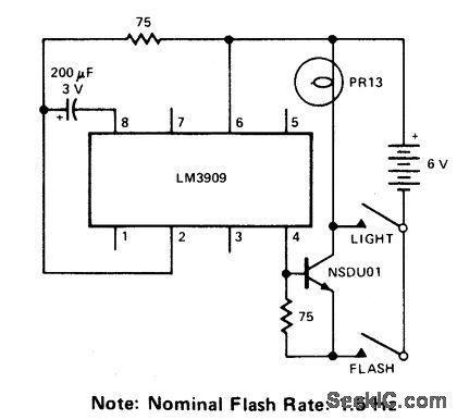
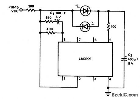
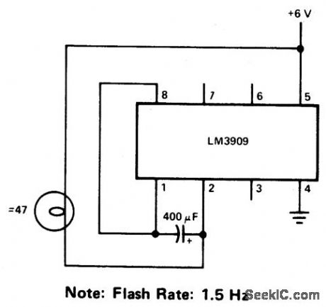
EMERGENCY_LANTERN/FLASHER_
Published:2009/7/1 1:47:00 Author:May
View full Circuit Diagram | Comments | Reading(786)
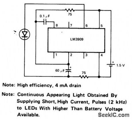
HIGH_EFFICIENCY__PARALLEL_CIRCUIT_FLASHER_
Published:2009/7/1 1:46:00 Author:May
View full Circuit Diagram | Comments | Reading(838)
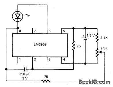
VARIABLE_FLASHER_
Published:2009/7/1 1:46:00 Author:May
View full Circuit Diagram | Comments | Reading(705)
MODULATED_LIGHT_BEAM_CIRCUIT_CANCELS_AMBIENT_LIGHT_EFFECTS
Published:2009/7/1 1:46:00 Author:May
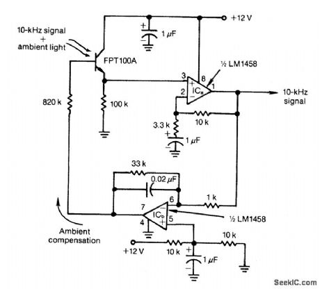
Feedback control of the phototransistor in this optical detector helps negate the effects of varying ambient light sources. The output of a modulated visible-light LED is detected, amplified, buffered, and fed through a low-pass ftlter. Ambient light signals below the LED's 10-kHz modulating rate reach the detector's base out of phase with incoming ambient light and cancel the undesired effects. (View)
View full Circuit Diagram | Comments | Reading(1164)
ALTERNATING_FLASHER
Published:2009/7/1 1:44:00 Author:May
View full Circuit Diagram | Comments | Reading(0)
LED_BOOSTER_
Published:2009/7/1 1:44:00 Author:May
View full Circuit Diagram | Comments | Reading(741)
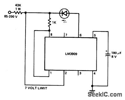
SAFE,HIGH_VOLTAGE_FLASHER
Published:2009/7/1 1:43:00 Author:May
View full Circuit Diagram | Comments | Reading(620)
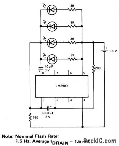
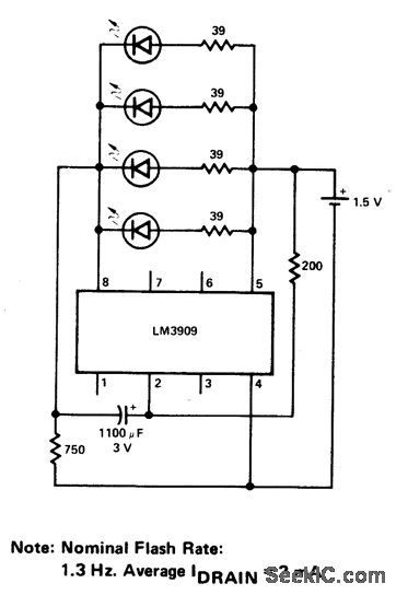
FLASHER_FOR_4_PARALLEL_LEDs_
Published:2009/7/1 1:43:00 Author:May
View full Circuit Diagram | Comments | Reading(735)
INCANDESCENT_BULB_FLASHER
Published:2009/7/1 1:41:00 Author:May
View full Circuit Diagram | Comments | Reading(786)
TANDEM_DIMMER_CROSS_FADER
Published:2009/7/1 1:22:00 Author:May
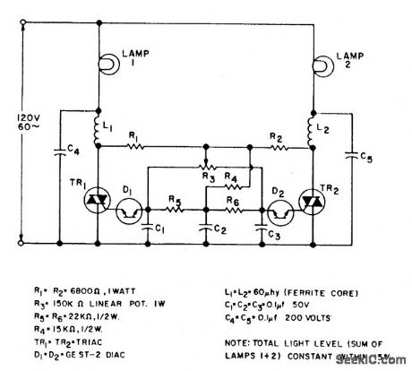
This cross fader circuit can be used for fading between two slide projectors. As R3 is moved to either side of center, one triac is fired earlier in each half cycle, and the other later. The total light output of both lamps stays about the same for any control position. (View)
View full Circuit Diagram | Comments | Reading(1277)
TRIAC_LAMP_DIMMER
Published:2009/7/1 1:19:00 Author:May
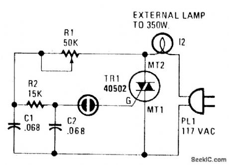
Using a heatsink, the TRIAC (TR1) can handle up to 350 watts. The neon lamp, I1, won't trip the gate until after it conducts and using R1, set the lighting wherever you want it. (View)
View full Circuit Diagram | Comments | Reading(0)
LAMP_DIMMER
Published:2009/7/1 1:17:00 Author:May
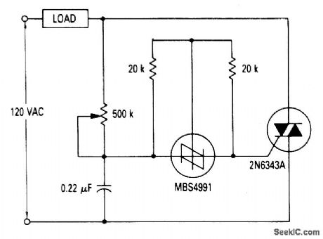
A full range power controller suitable for lamp dimming and similar applications operate from a 120 volt, 60 Hz ac source, and can control up to 1000 watts of power to incandescent bulbs. The power to the bulbs is varied by controlling the conduction angle of TRIAC Q1. At the end of each positive half-cycle when the applied voltage drops below that of the capacitor, gate current flows out of the SBS and it switches on, discharging the capaci-tor to near zero volts. The RC network shown across the TRIAC represents a typical snubber circuit that is normally adequate to prevent line transients from accidentally firing the TRIAC. (View)
View full Circuit Diagram | Comments | Reading(2070)
800_W_LIGHT_DIMMER
Published:2009/7/1 1:17:00 Author:May
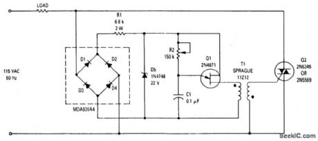
This wide-range light dimmer circuit uses a unijunction transistor and a pulse transformer to provide phase control for the TRIAC. The circuit operates from a 115 volt, 60 Hz source and can control up to 800 watts of power to incandescent tights. The power to the lights is controlled by varying the conduction angle of the TRIAC from 0° to about 170°. The power available at 170°conduction is better than 9770 of that at the full 180°. (View)
View full Circuit Diagram | Comments | Reading(4701)
WATER-LEVEL_INDICATOR
Published:2009/7/1 0:40:00 Author:May
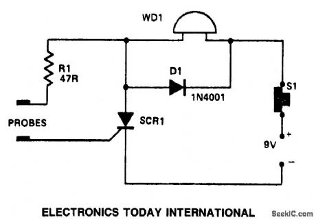
In this a waming device WD1 is in series with SCR1. When the liquid level causes a conductive path between the probes, the SCR conducts sounding WD1. The waming device may be a Sonalert (TM), a lamp or a buzzer.D1 acts as a transient suppressor. Press S1 to reset the circuit.
(View)
View full Circuit Diagram | Comments | Reading(1180)
LIE_DETECTOR
Published:2009/7/1 0:33:00 Author:May

The two probes shown are held in the hands and the skin resistance applies bias to the transistor. The 5 k ohm pot is set for zero deflection on the meter. When the subject is embarrassed or lies, sweating on the hands takes place, increasing the bias to the transistor and upsetting the bridge balance. (View)
View full Circuit Diagram | Comments | Reading(1965)
| Pages:51/72 At 204142434445464748495051525354555657585960Under 20 |
Circuit Categories
power supply circuit
Amplifier Circuit
Basic Circuit
LED and Light Circuit
Sensor Circuit
Signal Processing
Electrical Equipment Circuit
Control Circuit
Remote Control Circuit
A/D-D/A Converter Circuit
Audio Circuit
Measuring and Test Circuit
Communication Circuit
Computer-Related Circuit
555 Circuit
Automotive Circuit
Repairing Circuit