
LED and Light Circuit
Index 53
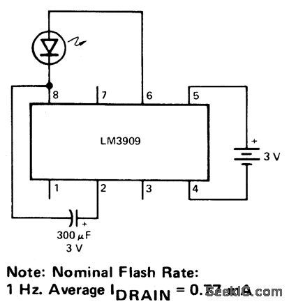
3_V_FLASHER_
Published:2009/6/30 4:32:00 Author:May
View full Circuit Diagram | Comments | Reading(763)
SINGLE_SOURCE_EMERGENCY_LIGHTING_SYSTEM
Published:2009/6/30 3:11:00 Author:May
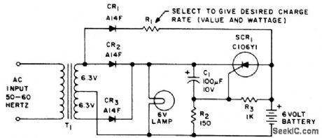
This emergency lighting system maintains a 6 volt battery at full charge and switches automatically from the ac supply to the battery. (View)
View full Circuit Diagram | Comments | Reading(3168)
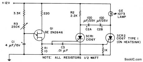
TARRY_LIGHT
Published:2009/6/30 3:06:00 Author:May
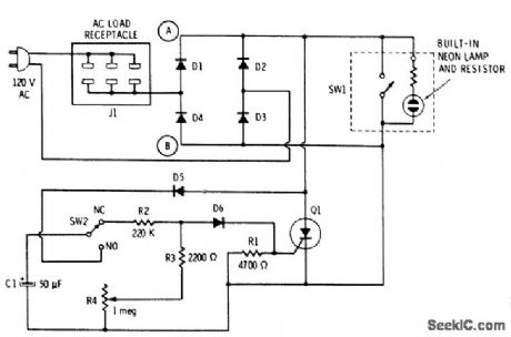
The push button and potentiometer initiate a time delay that turns a light on then automatically turns it off again after a predetermined time. The potentiometer can be set for a delay of a few secbnds to just under three minutes. When the push-button switch SW2 is pressed, capacitor C1 gets charged through D5 to the full dc voltage developed by the diode bridge. When the button is released, the charged capacitor is connected across the series combination of R2, R3, and potentiometer R4 whose setting determines the total resistance and thereby sets the time it takes for the capacitor to discharge. A steering diode, D6, connected to the junction of R2 and R3, and potentiometer R4 whose setting determines The total resistance and thereby sets the time it takes for the capacitor to discharge. Diode, D6 picks off a portion of this decaying dc voltage and applies it to the gates terminal of Q1, the SCR, triggering it into a conductive state. This SCR will remain on as long as there is sufficient voltage on its gate. As soon as this voltage decays below the minimum holding voltage of the SCR, it will tum off on the next line alternation. (View)
View full Circuit Diagram | Comments | Reading(845)
1_A_LAMP_FLASHER_
Published:2009/6/30 3:05:00 Author:May
View full Circuit Diagram | Comments | Reading(721)
LOW_VOLTAGE_FLASHER
Published:2009/6/30 3:02:00 Author:May
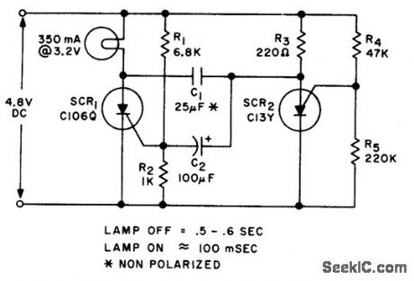
Circuit Notes
Applying voltage to the circuit triggers SCR1. With SCR1 on, the voltage on the anode of SCR2 rises until SCR2 triggers to commu-tate SCR1. The voltage on the gate of SCR1 will swing negative at this time, and only after a positive potential of 0.5 volt is once again attained, will SCR1 retrigger. The circuit could be used for higher voltage levels, but the peak negative voltage on the gate of SCR1 must be limited to less than 6 volts. (View)
View full Circuit Diagram | Comments | Reading(1023)
DC_FLASHER_WITH_ADJUSTABLE_ON_AND_OFF_TIME
Published:2009/6/30 2:59:00 Author:May
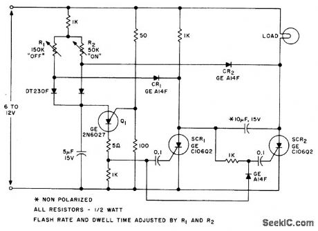
Circuit NotesThis circuit utilizes a power flip-fl。p and programmable unijunction(PUT)to obtainadjustable on and off times. (View)
View full Circuit Diagram | Comments | Reading(1152)
NEON_TUBE_FLASHER
Published:2009/6/30 2:57:00 Author:May
The voltage required to ignite the neon tube is obtained by using an ordinary filament transformer (240-6.3 V) in reverse. Battery drain is quite low, around 1 to 2 milliamps for a nine volt battery. The pulses from Q1, uni-junction transistor, operated as a relaxation oscillator and are applied to Q2 which in turn drives Q3 into saturation. The sharp rise in current through the 6.3 V winding of the trans-former as Q3 goes into saturation induces a high voltage in the secondary winding causing the neon to flash. The diode Dl protects the transistor from high voltage spikes generated when switching currents in the transformer. (View)
View full Circuit Diagram | Comments | Reading(1054)
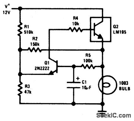
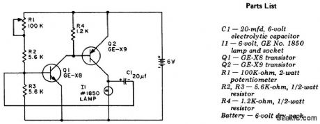
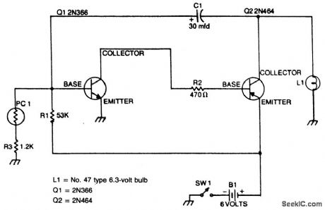
TRANSISTORIZED_FLASHER
Published:2009/6/30 2:55:00 Author:May
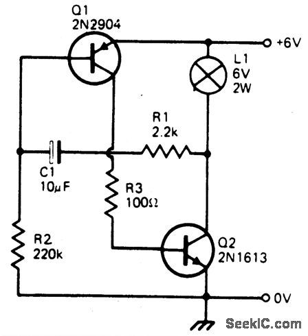
Circuit Notes
This simple circuit will flash a 6 volt lamp at a rate determined by the size ofcapacitor C1.It is most economical on power as it only draws current when the lamp is on. When the lamp is off, both transistors are biased off. (View)
View full Circuit Diagram | Comments | Reading(936)
AUTOMATIC_SAFETY_FLASHER
Published:2009/6/30 2:50:00 Author:May
Circuit Notes
This flasher only comes on at night. It furnishes a bright nighttime illumination, and shuts itself off automatically as soon as the sun comes up. The photocell must be mounted on top of the unit in such a way as to detect the greatest amount of available light. (View)
View full Circuit Diagram | Comments | Reading(816)
DUAL_LED_CMOS_FLASHER
Published:2009/6/30 2:49:00 Author:May

Circuit NotesInverters ICl-a and ICl-b form a multivi-brator and IC1-c is a buffer. Inverter IC1-d is connected so that its output is opposite that of ICl-c; when pin 6 is high, then pin 8 is low and vice versa. Because pins 6 and 8 are constantly changing state, first one LED and then the other is on since they are connected in reverse.The light seems to jump back and forth be-tween the LED's. The 470-ohm resistor limits LED current. Depending upon the supply vol-tage used, the value of the resistor may have to be changed to obtain maximum light output. To change the switching rate, change the value of the capacitor. (View)
View full Circuit Diagram | Comments | Reading(1816)
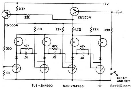
RING_COUNTER_FOR_INCANDESCENT_LAMPS
Published:2009/6/30 2:48:00 Author:May
View full Circuit Diagram | Comments | Reading(970)
FLIP_FLOP_FLASHER
Published:2009/6/30 2:43:00 Author:May
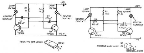
Circuit Notes
The flashing action is provided by a simple astable multivibrator timed to give a flashing rate of about 60 flashes for each lamp per minute. Circuit for positive earth systems uses NPN transistors. The other uses PNP transistors. (View)
View full Circuit Diagram | Comments | Reading(1043)
AUTO_BOAT_OR_BARRICADE_FLASHER
Published:2009/6/30 2:40:00 Author:May
View full Circuit Diagram | Comments | Reading(701)
Digital level display ( CD40147, CD4511 )
Published:2011/7/19 22:49:00 Author:zj | Keyword: Digital level display
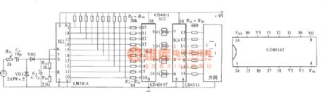
As shown in the figue thedigital level display candisplay audio amplifier output volume levels with digital display. Due to the adoption of a digital display tube,it displays0 ~ 9 levels.
(View)
View full Circuit Diagram | Comments | Reading(2483)
The night lock automatic lamp circuit
Published:2011/7/5 1:19:00 Author:zj | Keyword: The night lock, automatic lamp circuit
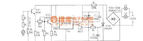
When you come back from the outside, it is so dark that unlocking is not unconvenient. As shown in the diagram it is a automatic lamp. When the key touches the door, the small lamp will light up automatically. After getting in the room indoor lamp will light up at the same time. At this time you can easily turn it on, the door lamp will automatically extinguish 20s later. Automatic lamp circuit is as shown in the figure. (View)
View full Circuit Diagram | Comments | Reading(823)
AURAL_INDICATOR
Published:2009/6/30 1:36:00 Author:May
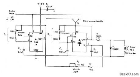
Provides attention-getting chirp sound, warble, or continuous tone when turned on by high input from burglaralarm sensor circuit. Second section of 556 timer provides optional frequency modulation of basic tone to give warbling effect. Chirp is achieved by gating tone oscillator on only during high states of warble oscillator. Aural sensitivity is maximum in range of 1-2 kHz, set by value of Rt2.-W. G. Jung, IC Timer Cookbook, Howard W. Sams, Indianapolis, IN, 1977, p 232-235. (View)
View full Circuit Diagram | Comments | Reading(849)
LED_INDICATES_LOW_VOLTAGE
Published:2009/6/29 21:27:00 Author:May
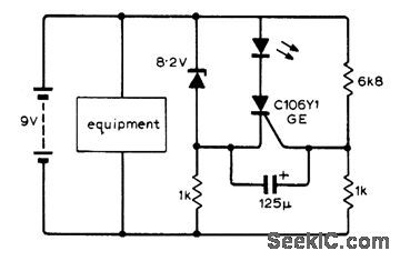
LED lights when output of 9-V rechargeable battery drops below minimum acceptable value of 8.3 V, to indicate need for recharging. Can also be used with transistor radio battery to indicate need for replacement. Zener is BZY85 C8V2 rated at 400 mW, with avalanche point at 7.7 V because of low current drawn by circuit. LED can be Hew-lett-Packard 5082-4440,-P.C. Parsonage, Low-Battery Voltage Indicator, Wireless World, Jan. 1973, p 31. (View)
View full Circuit Diagram | Comments | Reading(853)
Low voltage bulb used in 220V power circuit diagram
Published:2011/8/1 2:21:00 Author:Ecco | Keyword: Low voltage bulb, 220V power
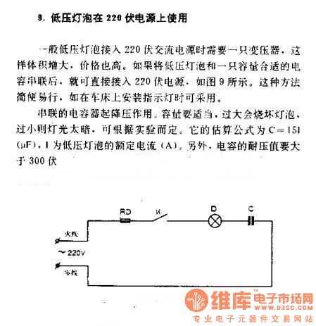
Low voltage bulb used in 220V power
Generally,the low-voltage light bulbsneeds a transformer when it is supplied by 220v AC power, then the volume increases, prices are high. If the low-voltage lamps and a suitable capacitor connect in series, they could access 220V power supply directly. According to figure 9, themethod is simple and easy, such as the installation of lights in the turning-lathe. Capacitors in series have the effect of reducing voltage. Thecapacitance should be appropriate, or burned out light bulbs when over, or the lighting is too dark when too small. It can be determined according to the experiment. Its estimating formula C = 15I (μF), I is the rated current of low-voltage lamp. In addition, the value of the capacitor voltage is greater than 300V. (View)
View full Circuit Diagram | Comments | Reading(1242)
COMPARATOR_DRIVES_LED
Published:2009/6/29 2:24:00 Author:May
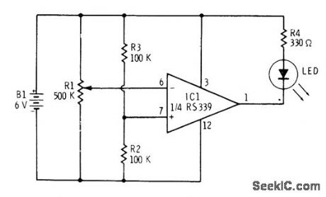
Simple classroom demonstrator of comparator action uses one section of RS339 quad comparator. Reference voltage applied to positive input of comparator is half of supply voltage. R1 serves as voltage divider applying variable voltage to inverting input. When voltage applied to pin 6 by R1 exceeds reference voltage on pin 1, comparator switches on and LED lights. R4 is chosen for use with Radio Shack 276-041 red LED.—F.M.Mims, Integrated Circuit Projects, Vol. 6, Radio Shack, Fort Worth TX, 1977, p 33-41. (View)
View full Circuit Diagram | Comments | Reading(966)
HM4246 touching stepping dimmer circuit
Published:2011/8/1 2:51:00 Author:Ecco | Keyword: touching stepping dimmer
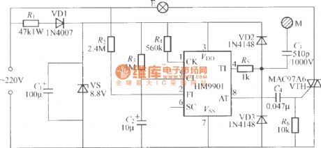
The touching stepping dimmer circuit composed of HM4246 IC is shown as the chart, when people repeatedly touch M, the light of light bulb E changes by the cycle of dark- medium- lightest- off- dark. And the corresponding crystal VTH thyristor conduction angle is 19, 75, 115 degree.
(View)
View full Circuit Diagram | Comments | Reading(914)
| Pages:53/72 At 204142434445464748495051525354555657585960Under 20 |
Circuit Categories
power supply circuit
Amplifier Circuit
Basic Circuit
LED and Light Circuit
Sensor Circuit
Signal Processing
Electrical Equipment Circuit
Control Circuit
Remote Control Circuit
A/D-D/A Converter Circuit
Audio Circuit
Measuring and Test Circuit
Communication Circuit
Computer-Related Circuit
555 Circuit
Automotive Circuit
Repairing Circuit