
LED and Light Circuit
Index 50
SOUND_TRIGGER_FOR_FLASH_UNIT
Published:2009/7/1 21:38:00 Author:May
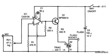
Circuit NotesThe circuit is based on operational amplifier IC1 used in the noninverting amplifier mode. R1 and 2 set the gain at about 500. RV1 (sensitivity) biases the noninverting input to the negative supply. Q1 provides the relatively high trigger current required by the triac. When a signal is received by the microphone, the signals are amplified (by IC1).The triac is triggered and a low resistance appears across its A1 and A2 terminals which are connected via the flashlead to the strobe. The circuit operates almost instantly, giving very little delay between the commencement of the sound and the flashgun being triggered. (View)
View full Circuit Diagram | Comments | Reading(1065)
VIDEO_MODULATOR
Published:2009/7/1 21:32:00 Author:May
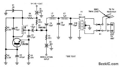
This circuit permits direct connection of composite video signals from video games and microcomputers to the antenna terminals of TV sets. The output signal level is controlled by the modulation input. (View)
View full Circuit Diagram | Comments | Reading(1)
VIDEO_MODULATOR_CIRCUIT
Published:2009/7/1 21:28:00 Author:May
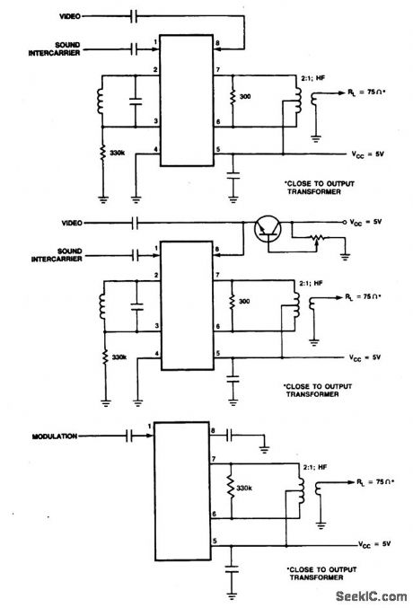
These are modulator circuits for modulation of video signals on a VHF/UHF carrier.The circuits require a 5V power supply and few external components for the negative modulation mode. For positive modulation an external clamp circuit is required. The circuits can be used as general-purpose modulators without additional external components. The IC is TDA6800. (View)
View full Circuit Diagram | Comments | Reading(839)
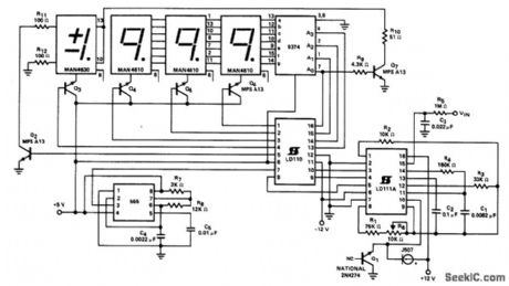
3_1_2_DIGIT_DVM(±2000_mV)COMMON_ANODE_DISPLAY
Published:2009/7/1 21:26:00 Author:May
View full Circuit Diagram | Comments | Reading(1093)
STROBING_LED_DISPLAY
Published:2009/7/1 21:11:00 Author:May
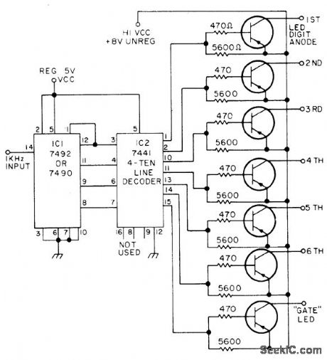
Applies power in sequence to segments of display, so fast that eye cannot detect flicker, to reduce drain on power supply. Input of 1000 Hz can be taken from timing chain of circuit that is driving display. 7492 divide-by-12 counter gives scan frequency of 83.3 Hz fordisplay. Binary output of 7492 is converted to 1-in-10 output by 7441 decoderfor sequential drive of 2N3904 PNP pass transistor that grounds LED which is to be lighted.-W. K.McKellips, Strobing Displays Is Cool, 73 Magazine, NovJDec. 1975, p 49-50. (View)
View full Circuit Diagram | Comments | Reading(1216)
8_DIGIT_MULTIPLEXED_LED
Published:2009/7/1 20:50:00 Author:May

CMOS multiplexing technique uses recirculating memory. Eight BCD words are parallel-loaded by strobe pulse into four MC14021 8-bit static shift registers. By feeding output back to input, information is continually recirculated within each shift register at clocked 3.5-kHz scan rate. Four serial output lines are fed to MC14511 7-segment decoder/driver. 3.5-kHz scan oscillator also clocksMC14022 octal counteridivider whose eight sequential output pulses form digitselect control.Commoncathode display is used.-A.Pshaenich, Interface Considerations for Numeric Display Systems, Motorola, Phoenix, AZ, 1975, AN-741, p 15. (View)
View full Circuit Diagram | Comments | Reading(2)
TWO_INPUT_RED_GREEN_LED_1
Published:2009/7/1 20:47:00 Author:May
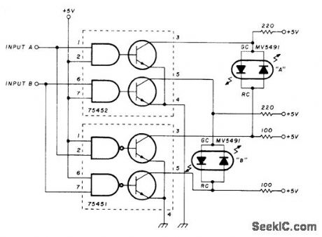
Uses Monsanto MV5491 having red and green LEDs in same housing, connected inversely in parallel so current in one direction gives green and reverse current gives red. Two different drivers are used, SN75452 noninverting and SN75451 inverting. Each LED pair shows one color for correct polarity at its driver input and other color for opposite polarity.-K. Powell, Novel Indicator Circuit, Ham Radio, April 1977, p 60-63. (View)
View full Circuit Diagram | Comments | Reading(1432)
TWO_INPUT_RED_GREEN_LED
Published:2009/7/1 20:47:00 Author:May
Uses Monsanto MV5491 having red and green LEDs in same housing, connected inversely in parallel so current in one direction gives green and reverse current gives red. Two different drivers are used, SN75452 noninverting and SN75451 inverting. Each LED pair shows one color for correct polarity at its driver input and other color for opposite polarity.-K. Powell, Novel Indicator Circuit, Ham Radio, April 1977, p 60-63. (View)
View full Circuit Diagram | Comments | Reading(1857)
4_DIGIT_DIRECT_DRIVE_LCD
Published:2009/7/1 20:27:00 Author:May
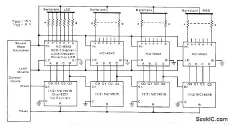
Each digit of liquid crystal display has sepalate counter,latch,decoder,and driver,Excitation signal also feeds LCD backplane When segmentis to be deenergized, backplane and segment drive signals have same phase and magnitude so there is no voltage across display. When segment is to be energized, signals are 180°out of phase so square-wave voltage is twice IC supply value.BCD inputs are generated from cascaded MC14518 dual BCD up counters.-A. Pshaenich, Interface Considerations for Numeric Display Systems, Motorola, Phoenix, AZ, 1975, AN-741,p 5. (View)
View full Circuit Diagram | Comments | Reading(2649)
8_DIGIT_LED_DRIVE
Published:2009/7/1 20:25:00 Author:May
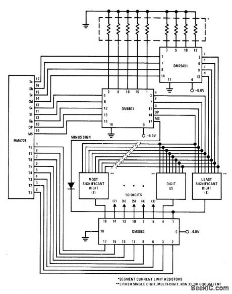
National DM8863 8-digit LED driver is used Inconjunction with DM75491 and DM8861 drivers for driving eight commonmode LED digits operating in multiplex mode.Circuit also provides logic control for decimal point.-C Carinalli, Driving 7-Segment LED Displays with National Semiconductor Circults, National Semiconductor,Santa Clara,CA,1974,AN-99,p 10. (View)
View full Circuit Diagram | Comments | Reading(2030)
CMOS_DRIVE_FOR_LCD
Published:2009/7/1 20:16:00 Author:May
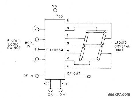
Seven-segment Iiquiocrystal display digit can be driven directly by CD4054A, CD4055A,or CD4056A CMOS because these circuits contain internal leve-shifting feature needed to convert 5-V input logic swings to 30-V peak AC sigpal required for driving dynamic-scattering LCD,- COS/MOS Integrated Circuits, RCA Solid State Dlvision,Somerville,NJ,1977,p 629. (View)
View full Circuit Diagram | Comments | Reading(1688)
TIMER_DRIVES_LED_DlSPLAY
Published:2009/7/1 19:44:00 Author:May
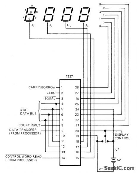
Intersil 7227 microprocesso-rcontrolled timer provides direct drive for LED display under supervision of microprocessor. Tristate 4-bit data bus serves to read in control word such as up/down, store reset, or load, then deliver counter data, feed in settable register word, or preset counter to initial value.-B. O'Neil, IC Timers-the Old Reliable 555 Has Company, EDN Magazine, Sept.5, 1977, p 89-93. (View)
View full Circuit Diagram | Comments | Reading(1339)
6_DIGIT_LED_DRIVER
Published:2009/7/1 5:39:00 Author:May
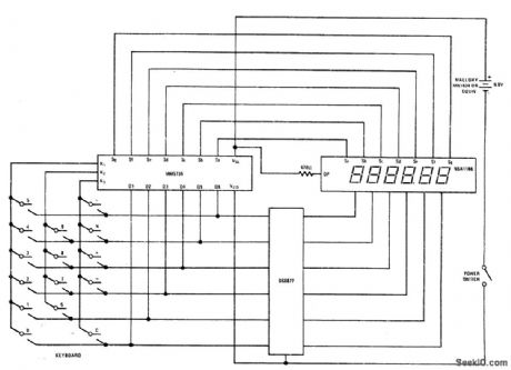
National DS8877 drive is shown in configuration for use with 6-digit calculator Digit current is in range of 5-50 mA,Driver requires no standby power and operates from either 4.5 V, 6 V, or 9 V.- Interface Databook National Semiconductor,Santa Clara,CA,1978, p 5-52-5-53. (View)
View full Circuit Diagram | Comments | Reading(944)
REDUCING_LED_POWER_DRAIN
Published:2009/7/1 4:52:00 Author:May
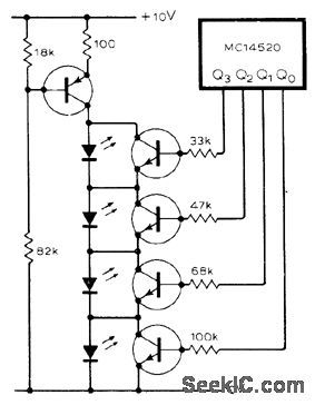
Arrangement of LEDs in groups of four with constant-current source greatly eliminates wastage of battery power Circuit shows utilization of this technique to display 4-bit binary number from CMOS counter.-T.R.Owen,L.E.D.Display,Wireless World,1976,P 72. (View)
View full Circuit Diagram | Comments | Reading(932)
4_DIGIT_GAS_DISPLAY
Published:2009/7/1 3:55:00 Author:May
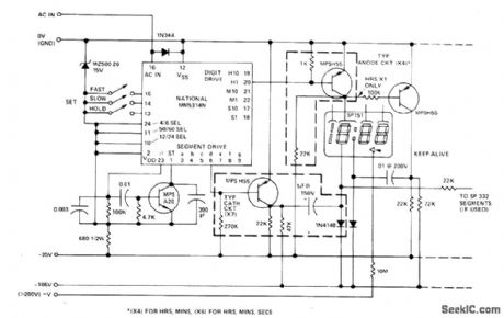
CMOS clock IC drives multidigit gas-discharge display, Simple circuit does not include alarm, flashing colon, and AM/ PM features. Seven segment-driver circuits and four digit-driver circuits are required, although only one of each is shown. Additional drivers are needed if seconds display is desired. Required supply voltages can be obtained from transformer-type supply driving diode bridge;regulation is not needed.-M.S.Robbins, Electronic Clocks and Watches, Howard W.Sans,Indianapolis,IN,1975,p 68-71. (View)
View full Circuit Diagram | Comments | Reading(1266)
2_INCH_LCD_NUMERALS
Published:2009/7/1 3:52:00 Author:May
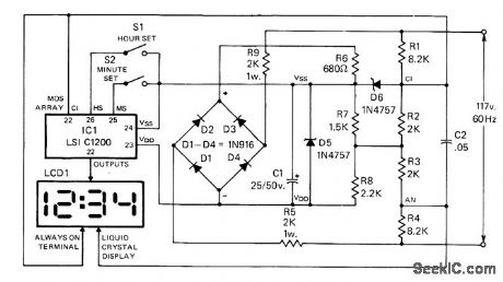
Uses C1200 clock IC made by LSI Computer Systems, having time set, logic, division for seconds, minutes, and hours, 7-segment decoding, and display drivers and switches. Four-digit liquid crystal display panel (LCD) is MGC-50. S1 and S2 advance minutes or hours on display at 2-Hz rate for setting time. To use as elapsed-time indicator, dose S1 and S2 simultaneously to generate reset pulse that sets timing change to zero. When both switches are released simultaneously, time count starts from zero.-R. F. Graf and G. J.Whalen,AGiant LCD Clock, C0, Feb. 1978, p 18-23 and 76. (View)
View full Circuit Diagram | Comments | Reading(1055)
CRYSTAL_CONTROLLED_SIGNAL_SOURCE
Published:2009/7/1 3:18:00 Author:May


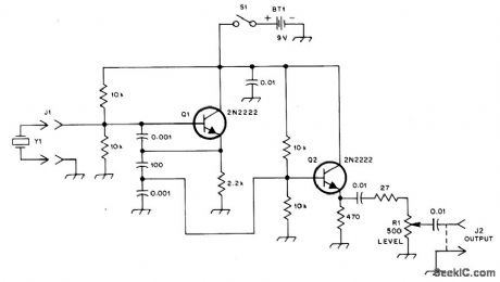
This general purpose signal source serves very well in signal-tracing applications.The output level is variable to more than 1 Vrms into a 50 Ω load. Almost any crystal in the 1 to 15 MHz range can be used. Q1 forms a Colpitts oscillator with the output taken from the emitter. A capacitive voltage divider (across the 2.2 K emitter resistor) reduces the voltage applied to the buffer amplifier, Q2. The buffer and emitter follower, provides the low input impedance necessary to drive 50 Ω loads.
(View)
View full Circuit Diagram | Comments | Reading(968)
6_DIGIT_DISPLAY
Published:2009/7/1 2:41:00 Author:May

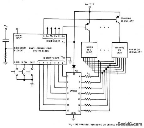
National DM8863 8-digit LED drivel serves as segment dlver for common-anode display of hours,minutes,and seconds,replacing total of 14 resistors and 7 transistors.-C. Carinalli, Driving 7-Segment LED Displays with National Semiconductor Circults, National Semiconductor, Santa Clara,CA,1974,AN-99,p 11. (View)
View full Circuit Diagram | Comments | Reading(1066)
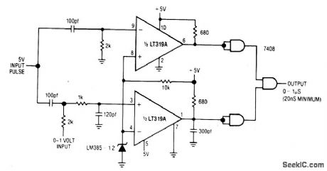
VOLTAGE_CONTROLLED_HIGH_SPEED_ONE_SHOT
Published:2009/7/1 2:36:00 Author:May
View full Circuit Diagram | Comments | Reading(699)
Limit_comparator_with_lamp_driver
Published:2009/7/24 4:30:00 Author:Jessie
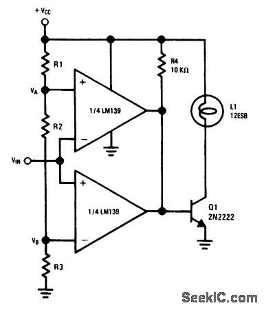
Fig. 15-14 This circuit provides a range of input voltages between which the outputs of both LM139 comparators will be off, allowing Q1 base current to flow through R4. This turns Q1 on and applies power to L1. If VIN changes to a value greater than VA, but less than VB, one LM139 switches on, shorting the Q1 base to ground. This turns lamp L1 off. If a pnp is used for Q1 (with emitter tied to + VCC), L1 will turn on when the input is above VA or below VB. The values of R1,R2, and R3 set the VA and VB points. For example, if VCC is 12 V, and all three resistors are the same value, VB is 4V, and VA is 8 V. National Semiconductor Linear Applications Handbook 1991, p. 260. (View)
View full Circuit Diagram | Comments | Reading(952)
| Pages:50/72 At 204142434445464748495051525354555657585960Under 20 |
Circuit Categories
power supply circuit
Amplifier Circuit
Basic Circuit
LED and Light Circuit
Sensor Circuit
Signal Processing
Electrical Equipment Circuit
Control Circuit
Remote Control Circuit
A/D-D/A Converter Circuit
Audio Circuit
Measuring and Test Circuit
Communication Circuit
Computer-Related Circuit
555 Circuit
Automotive Circuit
Repairing Circuit