
LED and Light Circuit
Index 48
OUT_OF_PHASE_DOUBLE_FLASHER
Published:2009/7/5 22:57:00 Author:May

Sectionsof National MM74C908/MM74C918 dual CMOS drivel are connected as Schmitt-triigger oscilIator,with LEDs at output of each section soLEDs will flash 180°out of phase High outputcurrent capability makes circuit suitable fordrivIng two LED arrays,-, CMOS Databook, National Semiconductor,Santa Clara,CA,1977,p 5-38-5-49. (View)
View full Circuit Diagram | Comments | Reading(927)
DRIVING_LED_ARRAY
Published:2009/7/5 22:52:00 Author:May

National MM74C908/MM74C918 dual MOS driver has sections connected as Sdlmitt-trigger oscillator,with R1 and R2 used to generate hysteresis,R3 and C are inverting feedback timing elements, and R4 is pulldown load for first driver. Output current drive capability is greater than 250 mA making circuit suitable for driving array of LEDs or lamps,- CMOS Databook, National Semiconductor,Santa Clara,CA,1977,p 5-38-5-49. (View)
View full Circuit Diagram | Comments | Reading(839)
SHIMMER_FOR_CHRISTMAS_LlGHTS
Published:2009/7/5 22:50:00 Author:May
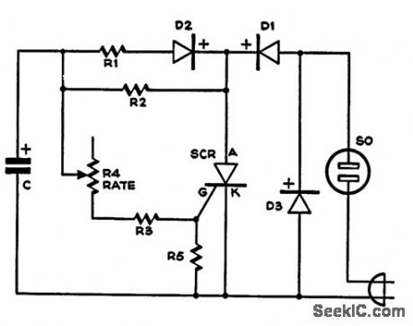
Circuit uses half of AC cycle to power lights conven-tionally. On other half-cycle, C charges and builds up voltage on gate of SCR When firing point is reached, SCB conducts and allows re mainder of this half-cycle to pass through Iight string. Result is flash that gives shimmer or strobe effect. C is 100-μF 50-V electrolytic, R1 is 2.7K, R2 is 22K, R3 is 3.3K R4 is 100K pot, and R5 is 1K. Diodes are Motorola HEP R0053. SCR is GE C106B1 or Motorola HEP R1221 mounted on heatsink.-R. F. Graf and G. J. Whalen, Add Shimmer to Your Christmas Lights, Popular Science, Dec. 1973, p 1211. (View)
View full Circuit Diagram | Comments | Reading(1456)
VARIABLE_FLASHER_FOR_LED
Published:2009/7/5 22:46:00 Author:May

Terminal connections of National LM3909 flasher IC give choice of three different flash rates for LED used as indicator in battery portable equipment. Extemal resistors provide additional adjustments of flash rate. Appropriate connections to pins 1 and 8 make flash-controlling internal resistance 3K, 6K or 9K Flasher operates at any supply voltage above 2 V, with low duty cycle to give long battery life.-P. Lefferts, Power.Miser Flasher IC Has Many Novel Applications, EDN Magazine, March 20, 1976, p 59-66. (View)
View full Circuit Diagram | Comments | Reading(1356)
MOVING_LIGHT_DISPLAY
Published:2009/7/5 21:16:00 Author:May
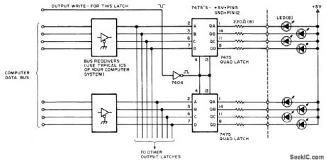
Computer-controlled blinking of LEDs arranged in circle or other pattern gives illusion of motion. One section of quad 7475 latch is assigned to each of several output ports of microprocessor. Decoding logic of output port determines when latch is addressed for output. Decoded WRITE signal latches data presented at bus receivers. lnterface can be extended to many registers in groups of eight, limited only by input/output addressing capability and power available for LEDs. Software is written to turn on LEDs in desired sequence and provide desired variable delays between blinks.-C. Helmers, There's More to Blinking Lights than Meets the Eye, BYTE, Jan. 1976, p 52-54. (View)
View full Circuit Diagram | Comments | Reading(2384)
The basic circuit diagram of LED
Published:2011/8/1 21:31:00 Author:Ecco | Keyword: basic circuit , LED
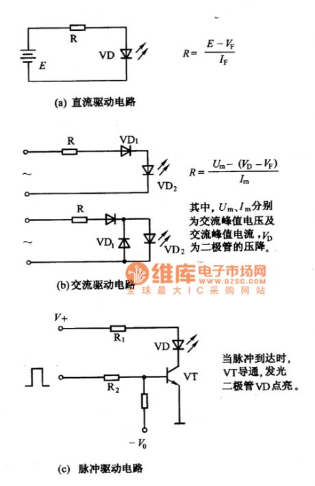
LEDs are current controlled devices, the current limiting resistor must be added in order to ensure their normal work. The basic circuit shownof LEDis shown as Figure 1.
(View)
View full Circuit Diagram | Comments | Reading(684)
OPAMP_DRIVE_FOR_LED_TUNING_LAMPS_
Published:2009/7/4 19:47:00 Author:May
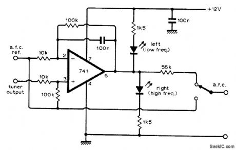
Opamp with l00k feedback resistor gives gain of 10 as optimum compromise for driving two LED tuning indicators in FM receiver,-R. D.Post, F.M Tuning Indicator, Wireless World,May 1975,p 220. (View)
View full Circuit Diagram | Comments | Reading(951)
LED_TUNING_INDICATOR
Published:2009/7/4 5:26:00 Author:May
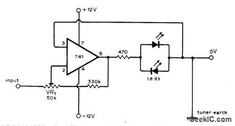
One LED is mounted at each end of tuning scale. Tuning pointer is moved away from whichever LED is on, to dead spot at which both are off, to obtain correct tuning point. Advantages of lights-off tuning include minimum current drain and indication of even very slight mistuning by having one light come on even slightly. Adjust VR1 to give wide enough dead spot so LEDs do not flicker on loud speech or music.-H. Hodgson, Simpler F.M.Tuning Indicator, Wireless World, Sept. 1975, p 413. (View)
View full Circuit Diagram | Comments | Reading(1070)
A_LITHIUM_BATTERY’S_STATE_OF_CHARGE_INDICATOR
Published:2009/7/3 4:26:00 Author:May
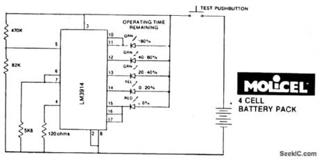
State-ofiCharge indication of a sloping-voltage discharge can be used as a state-of-charge indicator. A typical voltage comparator circuit that gives a visual indication of state-of-charge is shown. Components identified are for a 4-cell input voltage of 9.6 to 5.2 volts. (View)
View full Circuit Diagram | Comments | Reading(1212)
LOW_BATTERY_INDICATOR
Published:2009/7/3 4:23:00 Author:May
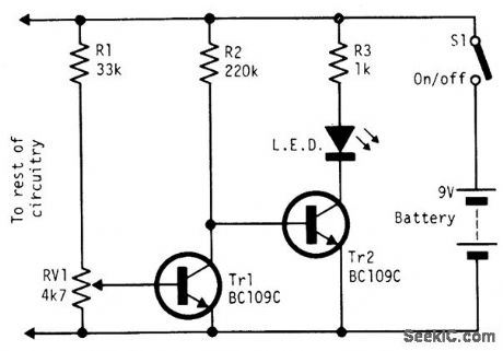

Under good battery conditions the LED is off. As the battery voltage falls, the LED begins to flash until, in the low battery condition, the LED lights continuously. Designed, for a 9-volt battery, with the values shown the LED flashes from 7.5 to 6.5 volts. (View)
View full Circuit Diagram | Comments | Reading(0)
PROM_WITH_LED_DlSPLAY
Published:2009/7/3 4:05:00 Author:May
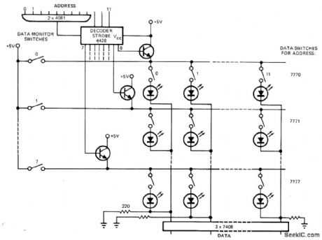
Developed for use in debugging small microprocessor systems.Uses LEDs in place of diodes as OR gates of 8 x 12-bit diode matrix memory which displays memory-cell content when word is addressed during execution of a program. Monitor switches can be used fordata displaywhen program is inserted. System was built to debug lntersil IM6100 μP. Since voltage output of diode array is too small for direct input to MOS circuit,7408 gates are used to boost high-level output.Article gives instructions for use of display.-K.S. Hojberg, Light-Emitting Memory Aids μP Debugging, EDN Magazine, May 5, 1977, p 107.
(View)
View full Circuit Diagram | Comments | Reading(764)
TONE_OUTPUT_FOR_DIGITAL_DISPLAY
Published:2009/7/3 3:45:00 Author:May


Converts BCD input from digital test gear to sequence of 10 different tones representing 0 to 9, for recognition of reading on digital display by blind radio operator or experimenter. Length of tone sequence equals number of digits displayed, plus sign indicator or half-digit if desired. Circuit shown is for 31/2 digits. Article describes operation of drcuit and gives construction details. Resistors R0-R9 (values inkilohms from 6.8K to 470K),determining frequencies of generated tones,are switched into VCO IC10 by IC9-D,R Pacholok,Digital to Audio Decoder,73 Magazine,Oct 1977,p 178-180. (View)
View full Circuit Diagram | Comments | Reading(844)
IGNITION_TIMING_LIGHT
Published:2009/7/3 3:35:00 Author:May
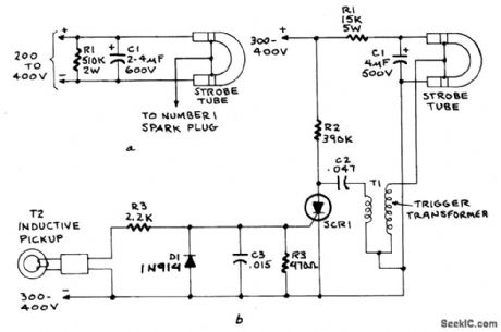
Figure A shows the circuit of a direct-trigger timing light. The trigger voltage is taken from the car's ignition circuit by a direct connection to a spark plug. A circuit using an inductive pickup is shown in Fig. B. A trigger transformer is used to develop the high-voltage pulse for triggering. The triggering circuit consists of T1, C1, SCR1, inductive pickup coil T2, and the waveshaping components in the SCR's gate circuit.When the spark plug fires, it induces a pulse in pickup coil T2 that triggers the SCR gate. The SCR fires and discharges C2 through the primary of T1. The secondary of T1 feeds a high-voltage pulse to the trigger electrode of the flash tube. That pulse causes the gas-usually neon or xenon-to ionize. The ionized gas provides a low-resistance path for Ct to discharge, thereby creating a brilliant flash of light.Resistor R1 limits current from the supply as the tube fires. When C1 is fully discharged the strobe tube cuts off and returns to its high-resistance state. The current through R2 is not enough to sustain conduction through SCR1, so it cuts off and remains off until it is re-triggered by a gate pulse. (View)
View full Circuit Diagram | Comments | Reading(7853)
PTC_THERMISTOR_AUTOMOTIVE_TEMPERATURE_INDICATOR
Published:2009/7/3 3:25:00 Author:May

The circuit is used to indicate two different water temperature trip points by tuming on LEDs when the temperatures are reached. The circuit is constructed around the LM2904 dual operational amplifter powered from the 12 V auto system. The thermistor is in series with a 10 kΩ resistor from ground to the positive 9.1 V point. The top of the thermistor is tied to both non-inverting inputs of the LM2904. The voltage at these inputs will change as the thermistor resistance changes with temperature. Each inverting input on the LM2904 has a reference, or threshold trip point, set by a 10 kΩ resistor and a 2 kΩ potentiometer in series across the 9.1 V regulated voltage. When this threshold is exceeded on the non-inverting input of LM2904, the TlL220 LED lights. The two trip points can be recalibrated or set to trip at different temperatures by adjusting the 2 kΩ potentiometer in each section. In addition to being used as waming lights as shown here, circuits can be added to turn on the fan motor or activate a relay. (View)
View full Circuit Diagram | Comments | Reading(2640)
AURAL_SWR_INDICATOR
Published:2009/7/3 3:25:00 Author:May
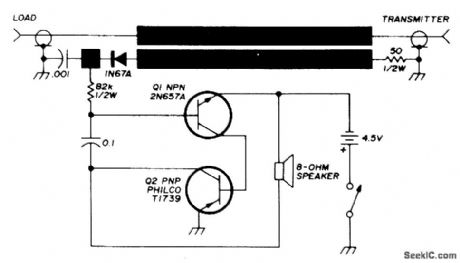
Permits blind amateur radio operator to check standing waves on transmission line and adjust for best possible impedance match between source and load.Darkened areas are foil strips 6 x 70mm, 1.5 mm apart, forming inductive trough that transfers RF energy from transmission line to simple aural monitor. Rectified RF energy changes bias on base of Q1, which makes tone increase in pitch with increasing voltage. ldling tone is about 500 Hz for values shown. Operates from three penlight batteries. Transmitter is peaked for maximum output on rising pitch, and matcbox antenna tuner is adjusted for minimum SWR on descending pitch. To lower audio tone, increase size of 82K resistor.-C. G. Bird, Aural SWR Indicator for the Visually Handicapped, Ham Radio, May 1976, p 53-53. (View)
View full Circuit Diagram | Comments | Reading(914)
AUTOMOTIVE_LIGHTS_ON_WARNING
Published:2009/7/3 3:21:00 Author:May
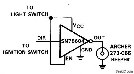
The SN75604, with input control logic but requiring only one supply rail, can be used in the lights on sensor and alarm driver. The device Vcc and enable inputs are connected to a voltage lead from the light switch. The direction control input is connected to a lead from the ignition switch. Only operation of the lights without the ignition will result in the alarm sounding. The beeper used in this application is an Archer 273-066 that will operate from 3 V to 28 V. At a typical 12 V level, it will produce a pulsating tone of about 95 dB at 30 cm. The alarm on current is about 12 mA when operating from a 12 V supply. (View)
View full Circuit Diagram | Comments | Reading(881)
GARAGE_STOP_LIGHT
Published:2009/7/3 3:10:00 Author:May
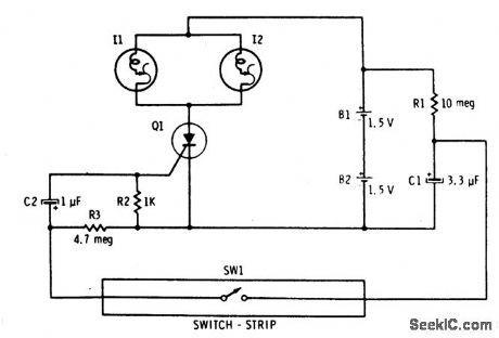
Capacitor C1 is permanently connected across the 3-volt supply through 10 megohm resistor R1. The capacitor charges (relatively slowly) to 3 volts. The instant switch SW1 is closed, it connects the charged capacitor (C1) in series with C2 and R2. Capacitor C2 starts to charge, placing a positive-going voltage on the gate of the SCR and causing it to turn on. The two parallel-connected self-flashing bulbs I1 and I2 turn on. They flash and turn off the SCR and the circuit is off the switch and C1 can recharge. (View)
View full Circuit Diagram | Comments | Reading(798)
144_MHz_FM_TRANSMITTER_
Published:2009/7/2 22:43:00 Author:May

Low-power circuit was developed for use with double-conversion continuous-tuning FM receiver suitable for either fixed or mobile communication on 2-meter amateur band. Q4-Q6 are part of RCA CA3018 IC. Power output with 12-V supply is about 1.5 VV. Two crystals are selected by slide switch; tuning can be compromised to use crys-tals whose 2-meter outputs are 1 MHz apart.Article also gives all circuits for receiver.-J. H.Ellison, Compact Package for Two-Meter FM, Ham Radio, Jan. 1974, p 36-44. (View)
View full Circuit Diagram | Comments | Reading(2502)
OUTPUT_STATUS_DlSPLAY
Published:2009/7/2 22:42:00 Author:May
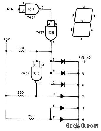
Monitors state of single bit and shows H or L on 7-segment display depending on status of data input. Uses two 7437 inverters and one DL-704 commoncathode display. Diode symbols represent segments of display (segment A is not needed for H or L). Power connections to 7437 inverter are +5 V to pin 14 and ground to pin 7.-G. Tomalesky, Bit Status Display, BYTE, Dec. 1977, p 197. (View)
View full Circuit Diagram | Comments | Reading(971)
8_TRACE_LOGIC_DISPLAY
Published:2009/7/2 22:25:00 Author:May

Adapter for standard oscilloscope shows time relationship between pulses at eight different locations in digital circuit, for troubleshooting and isolation of glitches. Almost any general-purpose CRO can be used, but triggered sweep improves usefulness. Multiplexer feeds each input in turn to Y input of CRO, under control of counter. Article covers operation and use of adapter.-R. A.Johnson, Eight Trace Scope Adapter, 73 Magazine, Sept. 1976, p 108-110. (View)
View full Circuit Diagram | Comments | Reading(1454)
| Pages:48/72 At 204142434445464748495051525354555657585960Under 20 |
Circuit Categories
power supply circuit
Amplifier Circuit
Basic Circuit
LED and Light Circuit
Sensor Circuit
Signal Processing
Electrical Equipment Circuit
Control Circuit
Remote Control Circuit
A/D-D/A Converter Circuit
Audio Circuit
Measuring and Test Circuit
Communication Circuit
Computer-Related Circuit
555 Circuit
Automotive Circuit
Repairing Circuit