
LED and Light Circuit
Index 55
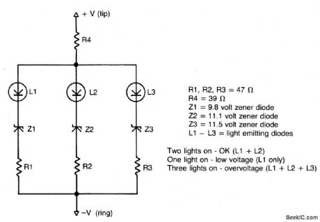
UNDERVOLTAGE_OVERVOLTAGE_INDICATOR
Published:2009/6/25 1:36:00 Author:May
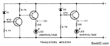
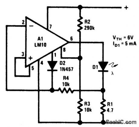
This circuit will make the LED glow if the monitored voltage goes below or above the value determined by zener diodesD1 and D2. (View)
View full Circuit Diagram | Comments | Reading(1381)
LIGHT_DIMMERS
Published:2009/6/25 1:35:00 Author:May
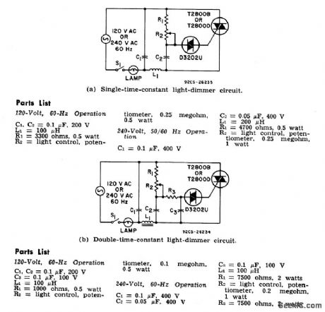
The two lamp-dimmer circuits differ in that (a) employs a s ingle-time-constant trigger network and (b) uses a double-time-constant trigger circuit that reduces hysteresis effects and thereby extends the effective range of the light-control potentiometer. (Hysteresisrefers to a difference in the control potentiometer setting at which the lamp turns on and the setting at which the light is extinguished.) The additional capacitor C2 in (b) reduces hysteresis by charging to a higher voltage than capacitor C3. During gate triggering, C3 discharges to form the gate current pulse.Capacitor C2, however, has a longer discharge time constant and this capacitor restores some of the charge removed from C3 by the gate current pulse. (View)
View full Circuit Diagram | Comments | Reading(1667)
STROBE_LIGHT
Published:2009/6/24 23:34:00 Author:May
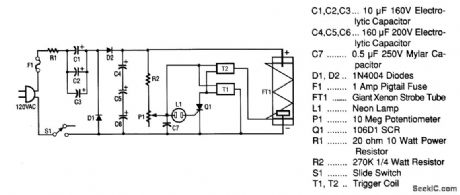
This strobe light operates from standard 120-Vac power,R1 limits the amount of current applied to the voltage doubler stage,which is comprtsed of C1,C2,C3,D1,D2,C4,C5,and C6 Capacitors C1,C2,and C3 are connected in parallel and form a capacitance of 30 μF at 160V. Capacitors C4, C5, and C6 are connected in serles and form an equivalent capacitor of about 53 μF at 480 V . Diodes D1 and D2 not only rectify the ac voltage,but also complete the vltage doubler stage,which convertsthe incoming 120 Vac to the appropriately 300 V that are required by the xenon strobe tube.
The next stage of the circuit is the neon relaxation oscillator and trigger stage This stage is made up of R2, P1,C7,L1,Q1,T1,and T2.As the storage capacitor (made up of C4,C5,and C6) reaches its full-capaclty charge,the voltage divider (made up of R2 and P1) applies voltage to capacitor C7. As C7 charges up,it reaches a threshold voltage level,SCR Q1. When Q1 has a positive pulse on its gate,it fires(causes a short from anode to cathode). That firing action discharges most of the energy stored in C7 into trigger transformers T1 and T2(which have secondaries connected in series to developer 8 kV). The frequency of the 8-kV pulses is determined by the setting of P1 and the value of C7. Because C7 is a fixed capacitor,only the Setting of P1 adjusts the flash rate in this circuit
As soon as an 8-kV pulse is applied from the secondary of T2 (trigger wire) to the trigger lead of FT1,it discharges storage capacitors C4,C5,and C6,which causes it to ionize (flash). The cycle thenrepeats itself until the power is removed from the circuit board by turning off S1 or removing the line cord. (View)
View full Circuit Diagram | Comments | Reading(3255)
CAPACITANCE_SWITCHED_LIGHT
Published:2009/6/24 22:58:00 Author:May
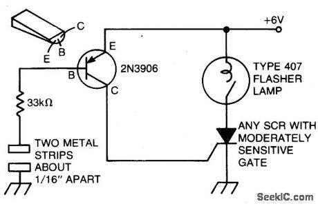
The battery powered light turns on easily, stays on for just a few seconds, and then turns off again. The circuit is triggered when you place a finger across the gap between two strips of metal, about 1/16th inch apart. Enough current will flow through your finger to trigger the SCR after being amplified by the 2N3906. Once the SCR is fired, current will flow through the bulb until its internal bimetal switch tums it off. 0nce that happens, the SCR will return to its nonconducting state. (View)
View full Circuit Diagram | Comments | Reading(880)
CAPACITANCE_OPERATED_BATTERY_POWERED_LIGHT
Published:2009/6/24 22:55:00 Author:May
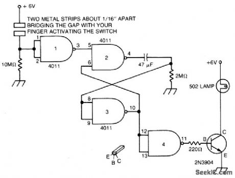
Touch the plate and the light will go on and remain on for a time determined by the time constant of the 47 μF capacitor and the 2M resistor. (View)
View full Circuit Diagram | Comments | Reading(810)
PHOTO_FLASH_SLAVE_UNIT
Published:2009/6/24 22:46:00 Author:May
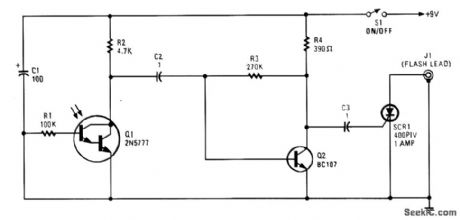
Phototransistor Q1 receives a light pulse from a photoflash unit. The pulse is accoupled to am-plifier Q2. It then triggers SCR1, which triggers a flash unit that is connected to J1. (View)
View full Circuit Diagram | Comments | Reading(1377)
AUTOMATIC_NIGHT_LIGHT
Published:2009/6/24 22:34:00 Author:May
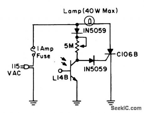
During daylight hours, the L14B photo-Darlington (JEDEC registered as 2N5777 through 2N5780) shunts all gate current to ground. At night, the L14B effectively provides a high resistance, diverting the current into the gate of the C106B and turning on the lamp. (View)
View full Circuit Diagram | Comments | Reading(1647)
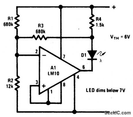
BATTERY_THRESHOLD_INDICATOR
Published:2009/6/24 22:32:00 Author:May
View full Circuit Diagram | Comments | Reading(684)
BATTERY_LEVEL_INDICATOR
Published:2009/6/24 22:32:00 Author:May
View full Circuit Diagram | Comments | Reading(107)
BATTERY_CHARGE_DISCHARGE_INDICATOR
Published:2009/6/24 22:28:00 Author:May
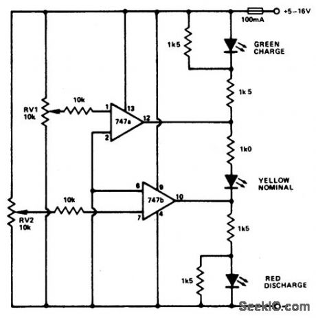
This circuit monitors car battery voltage. and yellow/green LEDs are on or off. For It provides an indication of nominal supply vol- example the red LED comes on at 11V, and the tage as well as low or high voltage. RV1 and green LED at 12V. The yellow LED is on RV2 adjust the point at which the red/yellow between these values. (View)
View full Circuit Diagram | Comments | Reading(1392)
BATTERY_CONDITION_INDICATOR
Published:2009/6/24 22:26:00 Author:May
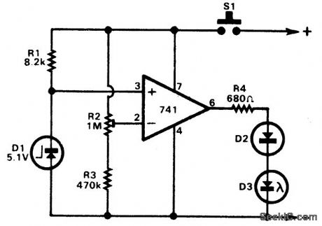
A 741 op amp is employed as a voltage comparator. The noninverting input is con-nected to zener reference source. Reference voltage is 5.IV. R2 is adjusted so that the vol-tage at the inverting input is half the supply voltage. When supply is higher than 10.2V, the LED will not light. When the supply falls just fractionally below the 10.2V level, the IC in-verting input will be slightly negative of the noninverting input, and the output will swing fully positive. The LED will light, indicating that the supply voltage has fallen to the preset threshold level. The LED can be made to light at other voltages by adjusting R2. (View)
View full Circuit Diagram | Comments | Reading(994)
SOLID_STATE_BATTERY_VOLTAGE_INDICATOR
Published:2009/6/24 22:24:00 Author:May
View full Circuit Diagram | Comments | Reading(766)
AUDIBLE_VOLTAGE_INDICATOR
Published:2009/6/24 22:13:00 Author:May

The audible voltmeter can be used to test for ac or dc voltages in a circuit. With S1 closed, the circuit can be used to test for voltages between 4 and 24 V, and when S1 is open, it can be used to check for the presence voltages of up to 200 V. (View)
View full Circuit Diagram | Comments | Reading(787)
SEQUENTIAL_FLASHER_FOR_AUTOMOTIVE_TURN_SIGNALS
Published:2009/6/24 21:58:00 Author:May
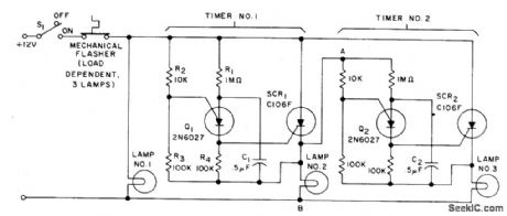
When the turn signal switch 51 is closed, lamp #1 will be activated and capacitor C1 will charge to the triggered voltage of Q1. As soon as the anode voltage on Q1 exceeds its gate voltage by 0.5 V, Q1 will switch into the low resistance mode, thereby triggering SCR1 to activate lamp #2 and the second timing circuit.After Q2 switches into the low resistance state, SCR2 will be triggered to activate lamp #3. When the thermal flasher interrupts the current to all three lamps, SCR1 and SCR2 are commutated and the circuit is ready for another cycle. (View)
View full Circuit Diagram | Comments | Reading(1421)
OVERSPEED_INDICATOR
Published:2009/6/24 21:56:00 Author:May
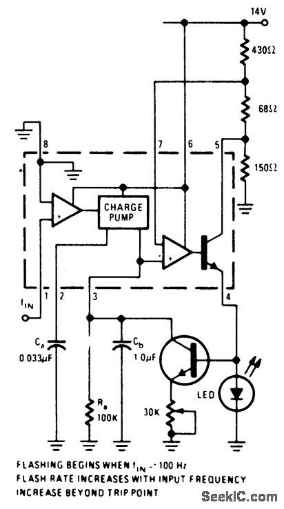
An op-amp comparator is used to compare the converter output with a dc threshold vol-tage. The circuit flashes the LED when the input frequency exceeds 100 Hz. Increases in frequency raise the average current out of ter-minal 3 so that frequencies above 100 Hz re-duce the charge time of C2, increasing the LED flashing rate. IC = LM2907 or LM2917 (View)
View full Circuit Diagram | Comments | Reading(1391)
VISUAL_ZERO_BEAT_INDICATOR
Published:2009/6/24 21:27:00 Author:May
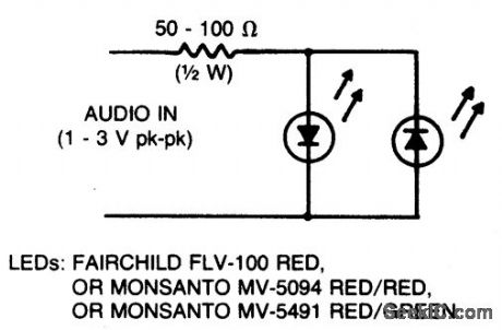
Light-emitting diodes connected with re-verse polarity provide a visual indication of zero-beat ffequency. Each LED is on for only half a cycle of the input. When the input fre-quency is more than 1 kilohertz away from the zero-beat frequency, both LEDs appear to be on all the time. As the input frequency comes within about 20 hertz of zero beat, the LEDs will flicker until zero beat is reached. Both LEDs glow or flicker until zero beat is reached, when they go out. (View)
View full Circuit Diagram | Comments | Reading(1615)
VISIBLE_VOLTAGE_INDICATOR_
Published:2009/6/24 21:25:00 Author:May
View full Circuit Diagram | Comments | Reading(644)
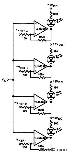
FIVE_STEP_VOLTAGE_LEVEL_INDICATOR
Published:2009/6/24 21:25:00 Author:May
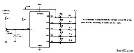
This circuit provides a visual indication of the input analog voltage level. It has a high input impedance at pin 8 and open-collector outputs capable of sinking up to 40 milliam-peres. It is suitable for driving a linear array of 5 LEDs to indicate the level is 5 steps. The voltage at the analog input should be in the range of zero to approximately one volt and should never exceed eight volts. (View)
View full Circuit Diagram | Comments | Reading(824)
THREE_STEP_LEVEL_INDICATOR
Published:2009/6/24 21:23:00 Author:May
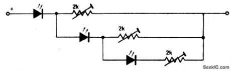
This circuit makes a very compact level indicator where a meter would be impractical or not justified due to cost. Resistor values will depend on type of LED used. For MV50 LEDs the resistors are 2 K for steps of approx 2 V and current drain with all three LEDs on of 5 mA.The chain can be extended but current drain increases rapidly and the first LED carries all the current drawn from the supply. (View)
View full Circuit Diagram | Comments | Reading(781)
BEAT_FREQUENCY_INDICATOR
Published:2009/6/24 21:22:00 Author:May
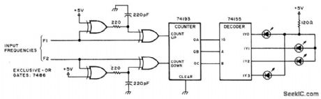
This circuit uses LEDs to display the beat frequency of two-tone oscillators. Only one LED is on at a time, and the apparent rotation of the dot is an exact indication of the best frequency. When f1 is greater than f2, a dot of light rotates clockwise; when f1 is less than f2, the dot rotates counterclockwise; and when f1 equals f2, there is no rotation. (View)
View full Circuit Diagram | Comments | Reading(933)
| Pages:55/72 At 204142434445464748495051525354555657585960Under 20 |
Circuit Categories
power supply circuit
Amplifier Circuit
Basic Circuit
LED and Light Circuit
Sensor Circuit
Signal Processing
Electrical Equipment Circuit
Control Circuit
Remote Control Circuit
A/D-D/A Converter Circuit
Audio Circuit
Measuring and Test Circuit
Communication Circuit
Computer-Related Circuit
555 Circuit
Automotive Circuit
Repairing Circuit