
LED and Light Circuit
Index 40
SOUND_TRIGGERED_FLASH
Published:2009/7/10 3:49:00 Author:May
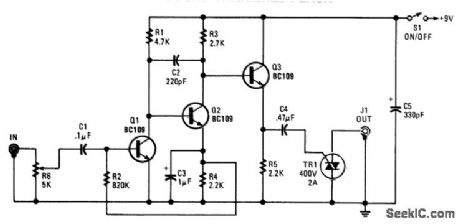
Audio input from a microphone drives amplifier Q1/Q2/Q3 to produce an ac voltage across R5. C4 couples this to TRI, causing it to conduct, triggering photoflash or other device that is connected to J1. (View)
View full Circuit Diagram | Comments | Reading(1344)
GATED_CLAMP_FOR_PPI_SWEEP
Published:2009/7/19 21:09:00 Author:Jessie
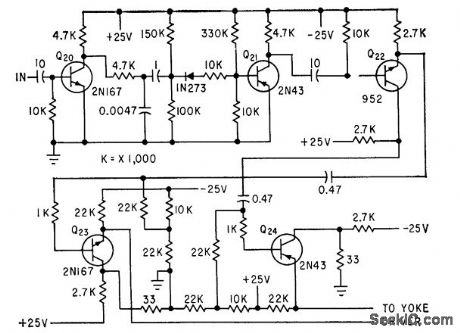
Uses monostable mvbr signal to generate reference level for yoke driven-C. E. Veazie, Transistorized Radar Sweep Circuits Using Low Power, Electronics, 32:26, p 46-47. (View)
View full Circuit Diagram | Comments | Reading(749)
SCR_SLAVE_FLASH
Published:2009/7/10 3:37:00 Author:May
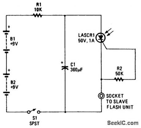
Using a light-activated SCR, this circuit can trigger a slave-flash unit. (View)
View full Circuit Diagram | Comments | Reading(988)
TACHOMETER
Published:2009/7/10 3:34:00 Author:May
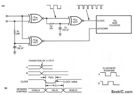
A standard shaft encoder's A and B ports generate square waves with the same frequency as the shaft turns. The phase of A will lead or lag that of B by 90°, depending on the direction of rotation. To obtain maximum resolution, the tachometer circuit must count every change of the state for the A and B signals. Each such change causes a change of state at IC1A's output, followed by a 1-μs negative pulse at the output of IC1C. These clock pulses' positive (trailing) edges cause the counter to count up or down, according to the direction of shaft rotation.You should set the R1C1 time constant, so that it is approximately twice that of the R2C2 product, to ensure adequate setup and hold times for the up/down signal with respect to the positive clock edges.IC1C supports this timing requirement by producing clock pulses of similar duration for either positive or negative transitions or IC1A.The exclusive-NOR logic of IC1B generates the correct polarity of the up/down signal when necessary, at the positive clock edges, by combining the A value with the B value just prior to a transition of A or B. C1 provides memory by sorting the B value voltage for about 2 μs. The maximum frequency for A or B is approximately (4R1C1)-1.
(View)
View full Circuit Diagram | Comments | Reading(0)
VARIABLE_STROBE_LIGHT
Published:2009/7/10 3:18:00 Author:May
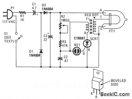
In this strobe-light, two circuits are needed; one circuit charges a capacitor placing 320 Vdc between the cathode and anode of the flashtube. The other circuit provides bursts of approximately 4000 V to trigger the flashtube into conduction. The voltage-doubler works by summing two equal voltages in series, which results in a doubling of the voltage. The 4000 V needed to trigger the flashtube is provided by transformer T1-a voltage step-up transformer that develops 4000 V across its secondary coil when current flows in the primary coil. Silicon-controlled rectifier SCR1 controls the current flow in the primary coil of T1. When SCR1 conducts, current flows suddenly in the primary coil and 4000 Vac spikes appear across the secondary coil. For conduction, SCR1 needs a negative and positive voltage on the cathode and anode, respectively, and a positive voltage on the gate. It is the function of components R2, R3, C3, and NE1 to provide that positive gate voltage and turn on SCR1. Potentiometer R2, resistor R3, and capacitor C3 form an rc timing circuit. Control of charging time of C3 is accomplished by varying that resistance in the circuit.When the voltage on C3 reaches the firing voltage of the neon bulb, it causes NE1 to conduct, thus placing a positive voltage, from C3, on the gate of SCR1. The SCR now turns on and C3 discharges through SCR1 and the primary coil of T1. The 4000 V that is developed across the secondary coil of T1 fires the xenon tube, causing a bright flash. The whole process then repeats itself with C3 charging up, NE1 firing to short out SCR1, and T1 developing 4000 V to trigger the xenon flashtube. (View)
View full Circuit Diagram | Comments | Reading(4037)
Warning_flasher_light
Published:2009/7/19 23:26:00 Author:Jessie
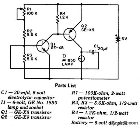
Warning flasher light. This device is handy to have around boats, cars, and camp sites. The circuit is a two-stage direct-coupled transistor amplifier connected as a free-running multivibrator. Both flash duration and flash interval can be adjusted by R1 (courtesy General Electric Company). (View)
View full Circuit Diagram | Comments | Reading(933)
Water_seepage_alarm
Published:2009/7/19 23:07:00 Author:Jessie
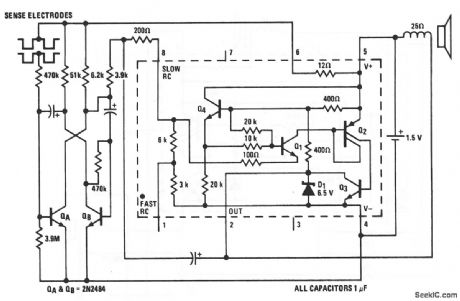
This LM3909 oscillator circuit can detect water seepage in darkrooms, laundry rooms,etc., and can be used on potentially damp floors with complete safety (because there is no connection to the power line), Also,the standby battery drain of about 100μA yields a battery life that is close to shelf life. The circuit operates as a multivibrator,which starts at about 1 Hz and oscillates faster as more leakage passes across the sense electrodes.The sensor consists of two electrodes(6 or 8 inches long)spaced about 1/8″apart.Two strips of stainless steel on insulators,or the appropriate zig - zag path cut in the copper cladding of a PC board can be used The sensor should be built into the base of the box In which the circuits are packaged.The bare PC board between the copper-sensing areas should be coated with warm wax so that moisture on the floor(not the moisture absorbed by the board)is detected.The circuit and sensor can be tested by simply touching a damp finger to the electrode gap.National Semiconductor Linear Applications Handbook 1991,p400 (View)
View full Circuit Diagram | Comments | Reading(2749)
Alternating_flasher
Published:2009/7/19 23:00:00 Author:Jessie
This LM3909 circuit is essentially a relaxation-type oscillator (chapter 5) that flashes two LEDs in sequence. With a 12-V supply, the repetition rate is about 2.5 kHz. Timing and storage capacitor C2 alternately charges through the upper LED and is discharged through the other LED by Q3 within the LM3909. If a red/green flasher is desired, the green LED should have its anode Of plus lead toward pin 5 (like the lower LED). A shorter, but higher, voltage pulse is available in this position. (View)
View full Circuit Diagram | Comments | Reading(0)
A_continuous_15_V_indicator
Published:2009/7/19 22:58:00 Author:Jessie
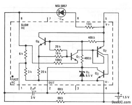
This LM3909 circuit shows a continuously appearing indicator light that is powered by 1.5 V. Duty cycle and frequency of the current pulses to the LED are increased (from that of Fig. 12-43B) until the average energy supplied provides sufficient light. At frequencies above 2 kHz, even the fastest movement of the light source or the observer's head will not produce significant flicker. This indicator draws about 12 mA from the 1.5-V battery, and is not intended as a long-life system. (View)
View full Circuit Diagram | Comments | Reading(810)
12_V_flasher
Published:2009/7/19 22:55:00 Author:Jessie
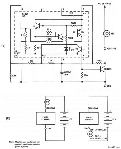
This LM3909 flasher circuit can be powered from an automotive storage battery, provides a 1-Hz flash, and can power a 600-mA lamp. A particular advantage of this circuit is that only two external wires are required (Fig. 12-50B), Also, no circuit failure can cause a battery drain greater than that of the #67 lamp.National Semiconductor, Linear Applications Handbook, 1991, p. 398. (View)
View full Circuit Diagram | Comments | Reading(956)
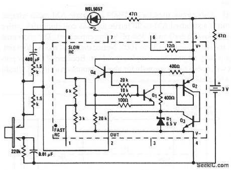
Mini_strobe_variable_flasher
Published:2009/7/19 22:53:00 Author:Jessie
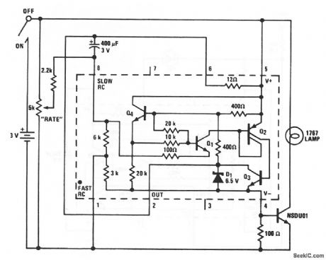
This LM3909 flasher circuit can be used as a variable-rate warning light, or for advertising or special effects. The rate control can adjust from no flashes to a continuous on. The miniature 1767 lamp can be flashed several times per second. As a toy, the flashing rate can be adjusted to mimic the strobes at rock concerts or the flicker of old-time movies. In a dark room, the flashes are almost fast enough to stop a person's motion. National Semiconductor Linear Applications Handbook 1991 p 397
(View)
View full Circuit Diagram | Comments | Reading(1188)
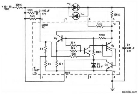
Safe_high_voltage_flasher_or_monitor
Published:2009/7/19 22:51:00 Author:Jessie
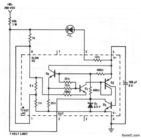
A high-voltage (85 to 200 V) power supply can be monitored at a remote location safely and with little current drain using this LM3909 circuit. If the 43-kΩ dropping resistor is located at the source end, voltages to the LED and LM3909 are limited to loss than 7 V above ground. A chart outlining operation of this circuit at various voltages appears on the LM3909 data sheet. (View)
View full Circuit Diagram | Comments | Reading(870)
6_V_flasher
Published:2009/7/19 22:49:00 Author:Jessie
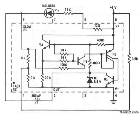
This circuit shows an LED flasher that uses an LM3909 with a 6-V supply. Notice that the circuit is similar to that of Fig. 12-43B, except that a 75-Ω resistor is required between pin 6 and the LED, a 3.9-kΩ resistor is used between pin 5 and pin 1, the 300-μF capacitor should be at least 3 V, and pin 5 receives +6V from the external source. The flashing rate remains at about 1 Hz.
Linear Applications Handbook. 1991. p 395 (View)
View full Circuit Diagram | Comments | Reading(930)
Low_power_fast_blinker
Published:2009/7/19 22:45:00 Author:Jessie

This circuit shows an LED flasher that uses an LM3909. Notice that the circuit is similar to that of Fig. 12-43B, except that a 1-kΩ resistor is connected between pin 4 and pin 8. This produces a little over three times the flashing rate of the Fig. 12-43B circuit. National Semiconductor Linear Applications Handbook 1991 p 395 (View)
View full Circuit Diagram | Comments | Reading(863)
Low_power_flashers
Published:2009/7/19 22:43:00 Author:Jessie
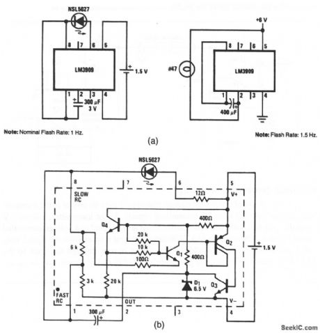
This circuit shows two simple flashers that use an LM3909. Figure 12-43B shows the internal circuit. Notice that the LM3909 requires only 1.5 V.However, 6 V is required when the LM3909 must drive a #47 lamp (or any similar load), instead of an LED. The flashing rate is determined by the value of the capacitor between pins 1 and 2. Iffiioo8l Semiconductor Linear Applications Handbook, 1991 p 394 (View)
View full Circuit Diagram | Comments | Reading(940)
Indicating_one_shot
Published:2009/7/19 23:23:00 Author:Jessie
In this application, the LM3909 delivers an approximate 1/2-s flash from the LED every time that the pushbutton makes contact (momentary or held).Such circuits are used with keyboards, limit switches, and other mechanical contacts that must feed data into electronic digital systems. National Semiconductor, Linear Applications Handbook 1991 p 406 (View)
View full Circuit Diagram | Comments | Reading(812)
Low_voltage_lamp_flasher_using_a_PUT_and_two_SCRs
Published:2009/7/19 23:23:00 Author:Jessie
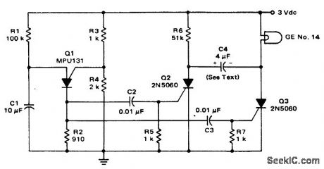
Low-voltage lamp flasher using a PUT and two SCRs. C4 is a nonpolarized type capacitor (courtesy Motorola Semiconductor Products Inc.). (View)
View full Circuit Diagram | Comments | Reading(754)
Trigger_switch_flasher
Published:2009/7/19 23:22:00 Author:Jessie
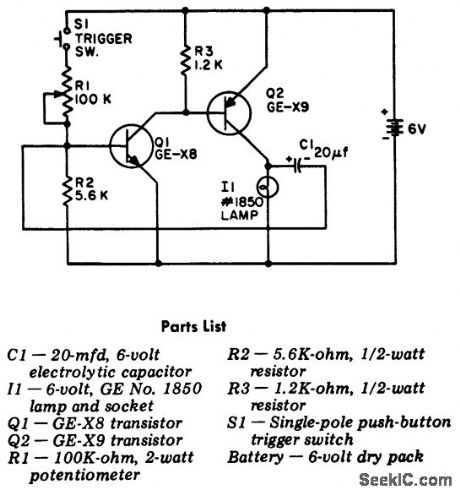
Trigger switch flasher. The flasher circuit is activated whenever pushbutton switch S1 is pressed. The circuit is a two-stage direct-coupled amplifier working as a multivibrator (courtesy General Electric Company). (View)
View full Circuit Diagram | Comments | Reading(1019)
LIGHT_RECEIVER
Published:2009/7/10 1:52:00 Author:May
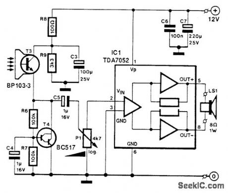
T3 is a photocell or phototransistor. T4 controls the emitter voltage of T3. IC1 is an audio amplfier to provide amplification of the signal from the photocell. (View)
View full Circuit Diagram | Comments | Reading(1028)
SOUND_TRACK_DRIVE
Published:2009/7/20 1:02:00 Author:Jessie

Dual-input amplifier drives 10-ohm recording galvanometer for variable-area optical sound track of 16.mm sound-on-film camera. Con be mounted directly on camera. Requires only two 6-V nickel-cadmium cells.-E. M. Tink, Transistorizing 16-Mm Tv Remote Film Camera, Electronics, 32:3, p 58-59. (View)
View full Circuit Diagram | Comments | Reading(1098)
| Pages:40/72 At 202122232425262728293031323334353637383940Under 20 |
Circuit Categories
power supply circuit
Amplifier Circuit
Basic Circuit
LED and Light Circuit
Sensor Circuit
Signal Processing
Electrical Equipment Circuit
Control Circuit
Remote Control Circuit
A/D-D/A Converter Circuit
Audio Circuit
Measuring and Test Circuit
Communication Circuit
Computer-Related Circuit
555 Circuit
Automotive Circuit
Repairing Circuit