
LED and Light Circuit
Index 33
SS0613 Touching stepless dimmer circuit
Published:2011/8/5 2:35:00 Author:Ecco | Keyword: Touching stepless dimmer
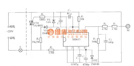
The touching stepless dimmer shown as the chart is composed of SS0613 IC, and it uses two-wire system connection, which can directly replace ordinary switch to transform the ordinary light into touching stepless dimmer.
(View)
View full Circuit Diagram | Comments | Reading(1365)
Fire-Fighting Emergency Light Circuit
Published:2011/8/5 21:15:00 Author:Robert | Keyword: Fire-Fighting, Emergency, Light
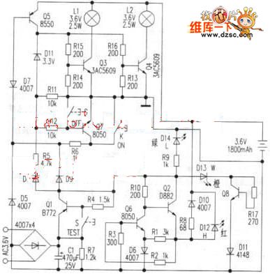
1. The battery charging circuit external power would charge for the battery with constant current through the Q2, Q6, R8, D10. When there is the external power supply, the charging current would charge the battery trough R8, D10 and also the charging indication lamp D12 would light.The picture shows the fire-fighting emergency light circuit.2.The light control circuit is made up of Q3, Q5, Q7 and key K, G. When there is no commercial power, by pressing the key K (openning), the Q5 would be saturated and conducted. The Q5's collector polar current would maintain the Q7 to keep conducted through R12. The D11 reverse breakdown is working in stable mode. The Q5's collector polar voltage would provide the bias voltage for the Q3, Q4 to make they conducted to light the L1 and L2. When pressing the key G (closing), the Q7 would be closed which remove the conducted conditions of Q5, and the lamp would be off. (View)
View full Circuit Diagram | Comments | Reading(2604)
VIDEO_NEGATIVE_VIEWER
Published:2009/7/14 21:58:00 Author:Jessie


This circuit will invert the video while maintaining sync polarity. Therefore, it will produce a negative image of the video signal. The sync is stripped by TR1, TR2, and IC1a and IC1b. Then it controls analog switches IC2a and IC2b to maintain sync polarity while switching in the inverted video produced by inverter TR3. TR4 is an emitter-follower for low output impedance. The unit was originally intended for viewing photographic negatives on a video monitor.
(View)
View full Circuit Diagram | Comments | Reading(1330)
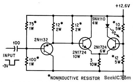
600_Hz_CLAMP
Published:2009/7/14 22:29:00 Author:Jessie
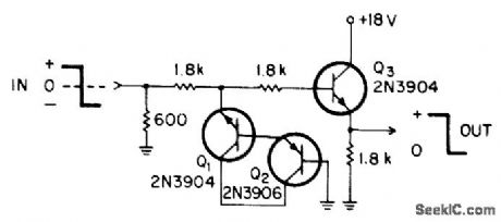
Polar clamp was developed to provide overvoltage input protection for ±6 VDC teleprinter signals at 10mA. Circuit will withstand input transients up to 120 VDC at 20mA. When input exceeds emitter-base break-down voltage of Q1, Q2 becomes forward-biased for clamping of input. With excessive negative input, Q1 is forward-biased and emitter-base path in Q2 completes clamping action.-R. R. Breazzano, A Polar Clamp, EDN|EEE Magazine, June 15, 1971, p 59. (View)
View full Circuit Diagram | Comments | Reading(891)
AUDIBLE_LINE_MONITOR
Published:2009/7/14 22:31:00 Author:Jessie
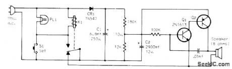

Audio oscillator coupled to simple relay circuit gives alerting tone when power fails even momentarily. C2 determines duration of tone. With 2900 μF, tone lasts about 1 s, as warning that clocks will need resetting, Q2 is any PNP audio power transistor, K1 is 115-V SPDT relay, and PL1 is neon lamp.-J. R. Nelson, Some Ideas for Monitoring A.C. Power Lines, CQ, July 1973, p 56. (View)
View full Circuit Diagram | Comments | Reading(989)
VOLTAGE_MONITOR
Published:2009/7/14 22:34:00 Author:Jessie
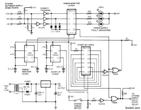
Developed for use in systems having multiple DC bias voltages, to prevent damage when one supply voltage goes down while other5 remain normal. Control circuit includes its own independent AC/DC supply that ensures protection even when equipment containing RAMs and MOS devices is turned off. Failure of AC supply for monitor shuts down entire system. Can be applied to any number of supplies by adding resistive dividers, Schmitt triggers, diodes, and latches as required. Closing system power switch activates solid-state relay for applying AC line voltage to main power supplies. Half of 556 dual timer and 74LS174 hex D latch inhibit voltage monitor until all supplies have stabilized, about 500 ms later. Other half of 556 then clocks 74LS175 power-monitor latch. System then operates normally as long as all D inputs to monitor latch stay at logic 0. If one supply fails, logic 1 appears at is latch input and next clock pulse initiates shutdown of sys-tem, LED identifies supply that has failed.-J. E. Draut, Voltage Monitor Protects Against Power-Supply Failures, EDN Magazine, Nov. 20, 1977, p 239-240. (View)
View full Circuit Diagram | Comments | Reading(4886)
FLIP_FLOP_DRIVES_GALLIUM_ARSENIDE_LAMP
Published:2009/7/14 21:16:00 Author:May
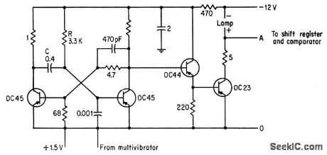
Pulses from mvbr (not shown) trigger flip-flop that feeds 1-amp current pulses to GaAs lamp through emitter-follower and power transistor. Used in high-speed punched tape, reader.-R. F. Broom and C. Hilsum, Diode Lamp Makes Tape Readers Easter, Electronics,36:20,p 44-45. (View)
View full Circuit Diagram | Comments | Reading(968)
LEVEL_DEIECIOR
Published:2009/7/14 21:09:00 Author:May
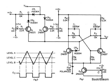
Used to provide switching function at two preset levels. R2 and Q1 determine highest level, while R3 and Q2 determine lowest level. Range of level adjustment is -10 +8 v.-H. Anway, Level Detecting Flip Flop With Adjustable Hysteresis. EEE ,14:1 ,p 63-64. (View)
View full Circuit Diagram | Comments | Reading(845)
LOOSE_GROUND_FLASHER
Published:2009/7/14 23:43:00 Author:Jessie
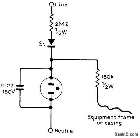
Uses ordinary neon lamp in series with silicon diode, with lamp normally dark. Gives warning by flashing if ground wire is accidentally or purposely disconnected from chassis of oscilloscope or other test instrument,-R. H. Troughton, Earth Warning Indicator, Wireless World, April 1977, p 62.
(View)
View full Circuit Diagram | Comments | Reading(1021)
TWINKLE_TREE
Published:2009/7/14 12:29:00 Author:May
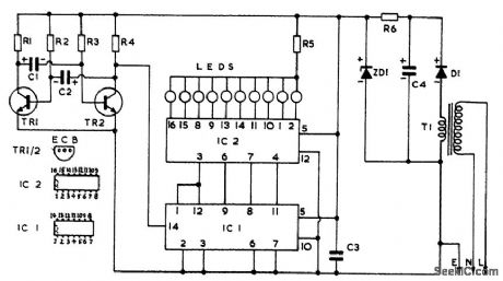
Twinkle Tree is an easy project for beginners to build, and its basic circuit has a number of useful applications. The circuit’s visible action appears as a string of 10 LEDs (light-emitting diodes) flashing on, one at a tiine, in sequence, this being repeated so long as the circuit is powered. The LEDs can be used on a small table decoration, in the form of a Christmas tree, or around a picture frame; or they can be placed at various points on a hanging decoration, such as a bunch of mistletoe, or can be incorporated in other decorations or modes. The LED light display provides an interesting and novel twinkling effect. (View)
View full Circuit Diagram | Comments | Reading(1406)
TIMED_NIGHT_LIGHT
Published:2009/7/14 12:27:00 Author:May
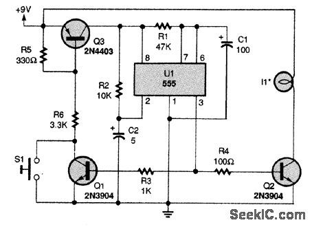
A small lamp is turned on via switch Q2 for a predetermined time. S1 initiates the 555 timer cycle, holding on Q1 and switch Q3, supplying power to the circuit, and Q2, turning on the lamp. At the end of the cycle, power is removed from the circuit because Q3 is cut off. Therefore, no current is drawn from the battery during standby. (View)
View full Circuit Diagram | Comments | Reading(1036)
BLOWN_FUSE_INDICATOR
Published:2009/7/14 5:38:00 Author:May
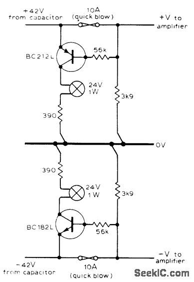
Used with quick-blow fuses in high-power audio amplifier using split power supply, when fuse blows, transistor shunting it is turned on and ρasses current to corresponding indicator lamp, Maximum current in blown-fuse condition is less than 1mA.-I, Flindell, Amplifier Blown-Fuse Indicator, Wireless World,Sept. 1976, p 73. (View)
View full Circuit Diagram | Comments | Reading(1685)
D_C_SUPPLY_FOR_FLUOURESCENT_LAMPS
Published:2009/7/14 5:06:00 Author:May
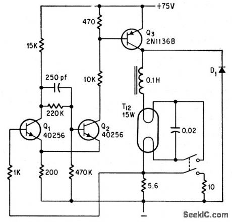
Lamp operates directly from d-c supply, without a-c conversion. Transistors form constant-current source that controls lamp current. Q3 is controlled by Schmitt trigger Q1.Q2. When lamp current exceeds preset value, voltage drop across 5.6-ohm resistor turns on Q1, thereby turning off Q2 and Q3. When lamp current falls, Q3 comes on again. To start, pushbutton closes circuit through lamp heaters and shunts 5.6-ohm resistor to give faster heating. When button is released, voltage surge caused by series inductor ignites lamp. Control circuit then varies lamp current 25% above and below its average value at 1-kc rate. Regulator losses are only 3 w.-D. B. Hoisington, Direct Current Regulator Drives Fluorescent Lamps, Electronics, 39:17, p 94-95. (View)
View full Circuit Diagram | Comments | Reading(996)
CURRENT_MODE_SWITCH_FOR_LIGHT_EMITTING_DIOE
Published:2009/7/14 4:33:00 Author:May
Peak currents of 2 amp ,with 50 nsec and fall, drive diode to give pulse-light communication. -E.L. Bonin, Drivers for Optical Diodes, Electronics, 37:32, p 77-82. (View)
View full Circuit Diagram | Comments | Reading(930)
HALLOWEEN_PUMPKIN_BLINKER
Published:2009/7/14 4:40:00 Author:May
Neon lamps blink alternately in eyes of pumpkin for 0.5-sec duration, with 0.5 sec between blinks. Will also serve as roadsid blinker .Although NE2's can be used, LNE17's can be brighter and more effective.-More Glow.Lamp Circuits, EEE, 12:2, p 106-108. (View)
View full Circuit Diagram | Comments | Reading(923)
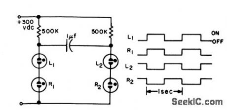
TWO_LAMP_STROBE_BOOSTS_FLASH_RATE
Published:2009/7/14 4:39:00 Author:May
Two discharge tubes provide shared cycle of operation, to boost stroboscope firing rate to 1,000 flashes per second. tamp circuit, with range-switched discharge capacitors, receives triggers in alternation.-L. H. Barrett, New Circuit Improves Stroboscope Versatility, Electronics, 32:32, p 116-118. (View)
View full Circuit Diagram | Comments | Reading(1001)
FLASH_DELAY
Published:2009/7/14 4:39:00 Author:May
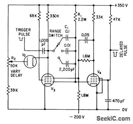
Supressor-gated sanatron pentode provides adjustable delay for changing spacing of lashes.-P. Scott, Microflash and Pulse Stimulator Tests Human Optical Response, Electronics, 34:27, p 48-51. (View)
View full Circuit Diagram | Comments | Reading(820)
FLASH_TUBE_DRIVE
Published:2009/7/14 4:39:00 Author:May
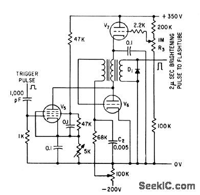
Generates low-impedance positive pulses having adjustable amplitude but constant durcttion, for driving flash tube to give same intensity-time characteristic as other fiash tubes having different colors.-P. Scott, Microflash and Pulse Stimulator Tests Human Optical Response, Electronics, 34:27, p 48-51. (View)
View full Circuit Diagram | Comments | Reading(883)
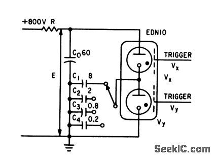
STROBE_RATEMETER
Published:2009/7/14 4:38:00 Author:May
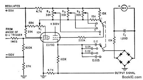
Flash role is metered by measuring mean charging current through capacitor supplied With constant-amplitude pulse voltage,-L. H. Barrett, New Circuit Improves Stroboscope Versatility, Electronics ,32:32,p 116-118. (View)
View full Circuit Diagram | Comments | Reading(890)
1_CPS_FLASHER
Published:2009/7/14 4:37:00 Author:May
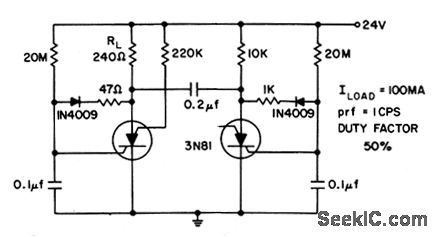
When one scs triggers on, 0.2-mid commutating capacitor turns off other scs and charges its gate capacitor to negative potential. At point in charging determined by 20-meg resistor, scs is retriggered .Battery power is delivered to load with 88% efficiency.- Transistor Manual, Seventh Edition, General Electric Co., 1964, p 434. (View)
View full Circuit Diagram | Comments | Reading(869)
| Pages:33/72 At 202122232425262728293031323334353637383940Under 20 |
Circuit Categories
power supply circuit
Amplifier Circuit
Basic Circuit
LED and Light Circuit
Sensor Circuit
Signal Processing
Electrical Equipment Circuit
Control Circuit
Remote Control Circuit
A/D-D/A Converter Circuit
Audio Circuit
Measuring and Test Circuit
Communication Circuit
Computer-Related Circuit
555 Circuit
Automotive Circuit
Repairing Circuit