
LED and Light Circuit
Index 37
MULTIPLE_LED_FLASHER
Published:2009/7/13 11:40:00 Author:May
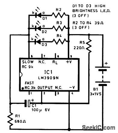
This is a circuit diagram for driving multiple LEDs from a single LM3909 flasher chip. (View)
View full Circuit Diagram | Comments | Reading(1903)
12_V_LED_FLASHER_1
Published:2009/7/13 11:37:00 Author:May

The figure shows a 12-V LED flasher configuration. (View)
View full Circuit Diagram | Comments | Reading(1119)
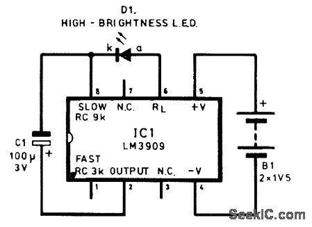
MODEL_AIRCRAFT_LED_FLASHER
Published:2009/7/13 11:28:00 Author:May
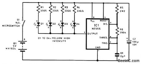
This circuit was used to simulate machine gun firing on a model aircraft, but it can also be used for other applications. (View)
View full Circuit Diagram | Comments | Reading(1212)
12_V_LED_FLASHER
Published:2009/7/13 11:26:00 Author:May
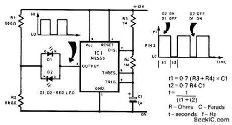
This is the circuit diagram of an LED flasher suitable for 12-V operation. The liming formulas are also shown. (View)
View full Circuit Diagram | Comments | Reading(1056)
SINGLE_LED_FLASHER
Published:2009/7/13 11:25:00 Author:May
This is a circuit diagram of an LED flasher with few components. (View)
View full Circuit Diagram | Comments | Reading(1403)
RAINBOW_FLASHER
Published:2009/7/13 11:24:00 Author:May
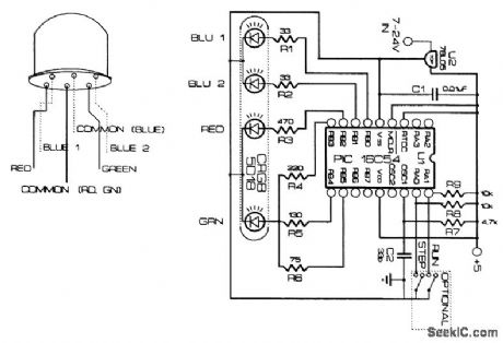
This device flashes a multicolor RGB LED in various colors, in a sequence and speed determined by the PIC 16C54 software. The LED is by Cree Electronics. (View)
View full Circuit Diagram | Comments | Reading(2330)
MODEL_FIRE_ENGINE_FLASHER_CIRCUIT
Published:2009/7/13 11:20:00 Author:May
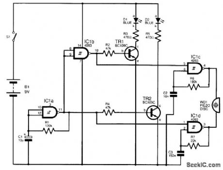
This circuit was designed to add both a blue flashing light sequence and a two-tone siren effect to a model fire engine. IC1 is a quad NAND Schmitt trigger, and IC1a provides a low-frequency waveform, which is inverted by IC1b. Complementary outputs are obtained, which drive transistors TR1 and TR2. These driver transistors operate D1 and D2, which are two blueLEDs. The model had a blue translucent molding on its roof and yielded a surprisingly realistic effect. The outputs fromIC1a and IC1b are also used to control gated astables IC1c and IC1d, which are set to oscillate at different frequencies to simulate a typical British two-tone siren, sounded by WD1, a piezo disk. Battery B1 should be an alkaline or rechargeable9-V type because the current consumption is relatively high. S1 was a slide switch fitted on the rear of the vehicle.The sounder is optional.
(View)
View full Circuit Diagram | Comments | Reading(1632)
NOVELTY_LED_FLASHER
Published:2009/7/13 11:16:00 Author:May
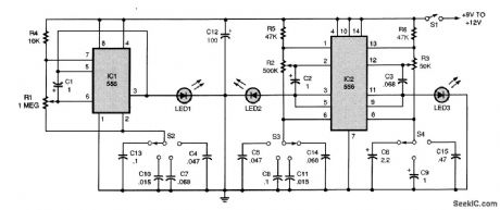
The circuit contains three oscillators, one based on a 555 (IC1) and the others centered around a 556 (IC2). When S1 is on, each oscillator's LED (LED1, LED2, or LED3) will flash rhythmically, according to the setting of its potentiometer (R1, R2, or R3), and the capacitor selected by its switch (S2, S3, or S4). Each oscillator output is capable of driving up to 20 jumbo LEDs con-nected in parallel. Arrange the LEDs to suit your taste. The circuit will operate on a battery or any 9- to 12-Vdc source. (View)
View full Circuit Diagram | Comments | Reading(1907)
AC_LIGHT_FLASHER
Published:2009/7/13 11:12:00 Author:May
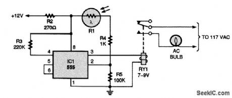
This circuit uses a 555 timer that is configured in an unusual way in that trigger pin 2 is activated by the voltage from a photocell to sense when the lamp is lit. The relay time constants affect the flash rate. (View)
View full Circuit Diagram | Comments | Reading(1128)
LIGHTS_ON_INDICATOR
Published:2009/7/13 5:17:00 Author:May
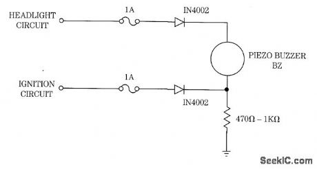
The buzzer (BZ) will sound if the ignition is off and the headlights are on (View)
View full Circuit Diagram | Comments | Reading(918)
DAYTIME_RUNNING_LIGHT_CIRCUIT
Published:2009/7/13 5:02:00 Author:May
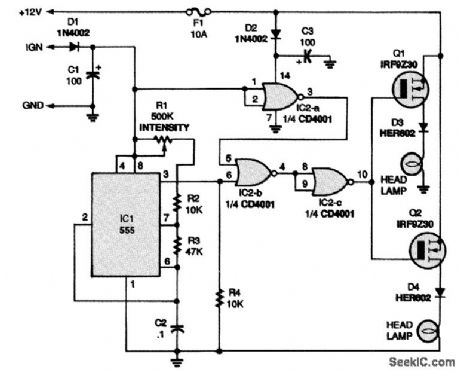
The DRL circuit is a variable-duty-cycle power oscillator that allows pulses of current to be applied to the headlights whenever the ignition of the vehicle is turned on. The 12-Vdc power that drives the circuit is taken from two sources in the vehicle. Power for the headlights is provided by the vehicular battery and generator system, and is input through fuse F1 to the circuit. The power source for the digital or logic part of the circuit is the + 12-V line that feeds the ignition system of the vehicle. When the ignition is turned on, the circuit is on, and when the ignition is turned off, so is the circuit. When the ignition is on, power is applied through D1 to operate IC1, a 555 timer that is connected as a free-running multivibrator. Pin 3 of IC1 provides the output of the oscillator; the duty cycle is determined by the following ratio:
(R1 + R2) /R3
Potentiometer R1 allows the duty cycle of the negative part of the waveform to be adjusted from about 10 percent to almost 50 percent. Adjustment capability is provided so that the intensity of illumination can be set as desired. A set of logic gates (IC2), powered by the battery and generator, is used to control the operation of the circuit. When the ignition is off, the logic output of pin 3 of IC2-a is high. Under that high-logic condition, the transistors are not forward-biased and the headlights remain off. When the ignition is on, the oscillator is powered through D1. The pulse train output of IC1 appears simultaneously at the gates of Q1 and Q2. Those two transistors then feed + 12-V pulses through their respective diodes, D3 and D4, to the low-beam headlights of the vehicle. The diodes provide isolation between the DRL circuit and the electrical system of the vehicle. The design of the circuit makes it possible to add second pairs of hex-FET transistors and corresponding diodes to the circuit and have them driven by IC2-c. Thus, if desired, the taillights of the vehicle may also be used for DRL operation. (View)
View full Circuit Diagram | Comments | Reading(5425)
CAR_BATTERY_VOLTMETER_WITH_BAR_GRAPH_DISPLAY
Published:2009/7/13 4:55:00 Author:May
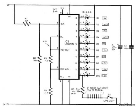
This uses an LM3914 bar-graph display, IC1, adapted to measure its own supply, so you simply wire it directly across the 12-V supply voltage (right way round-watch pins 2 and 3 carefully!). Ten LEDs, D1 to D10, will indicate the applied battery voltage, ranging from 1.5 to 15 V. The IC contains 10 internal comparators connected totem-pole-like, each sinking current through an LED. They compare an internal reference voltage against the chip's input voltage, at pin 5. Set the IC reference voltage with resistors R3 and R4 to just under 5 V. This means that one LED will light for every 500 mV (5 V reference/10 stages) increase in the signal. To enable this to be used to read a 12-V battery (the chip's own supply rail, in this case), resistors R1 and R2 are included as a divider: An input of roughly +15 V will cause D1 to light. When the voltage gradually falls, LEDs D2 to D10 will progressively illuminate. The circuit is set as a moving dot display. Connect pin 9 to the positive rail for a bar-graph display (not recommended because of the current consumption). Because the 10 outputs are effectively constant-current sinks, the LEDs will glow at a level independent of the changes in the supply rail; they won't dim when the rail drops. However, the first two or three display LEDs (D8 to D10) are superfluous in this application, because the LM3914 won't operate correctly below a rail of about +5 V. (View)
View full Circuit Diagram | Comments | Reading(3639)
FREE_RUNNING_COUNTER_DISPLAY
Published:2009/7/13 4:46:00 Author:May
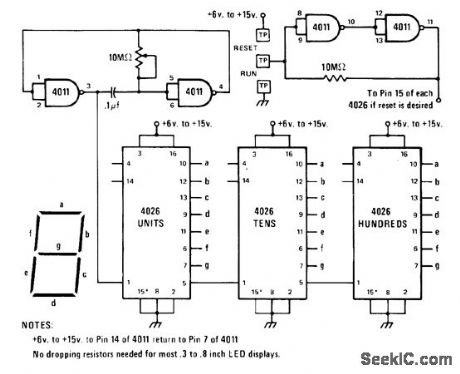
Atten-tion-getting circuit simply counts at predetermined rate while driving 3-digit display using 7-segment LEDs. Circuit uses two sections of 4011 CM0S quad NAND gate to generate pulses at rate controlled by 100-megohm pot. Pulses trigger 4026 counters connected as shown, with outputs a-g of each going to 7-segment LED dis-play. When all three displays reach 9, next pulse resets all to0 and count continues. Auxiliary circuit at upper right uses remaining sections of 4011 as flip-flop controlled by touch-plate switches; bridging gap between center and grounded plates with finger makes counter run. Bridging other gap resets counter to 0 and holds it there. If reset is not used, connect input pins 8, 9, 12, and 13 of unused gates to pin 14. -J. A. Sandler, 9 Easy to Build Projects under $9, Mod-em Electronics, July 1978, p 53-56. (View)
View full Circuit Diagram | Comments | Reading(3625)
TRICOLOR_LED_PEAK_INDICATOR_CIRCUIT
Published:2009/7/13 4:44:00 Author:May
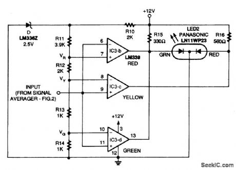
This is a tricolor LED circuit. With a low input level, LED2 is off. As the input voltage increases, LED2 turns on and glows first green, then yellow, and finally red. Resistor R10 and 2.5-V precision voltage reference IC4 provide a precision voltage reference that is further subdivided by resistors R11, R12, R13, and R14, This chain of resistors creates three different reference voltages that set the voltage thresholds for the three LEDs, which are fed to the three comparators along with the input signal. The output of these comparators is then connected to LED2. If the output of all of the comparators is floating, the red and green dies in the tricolor LED are biased ON by R15 and R16, causing LED2 to glow yellow. However, if the output of a comparator is internally grounded, the connected color element will be pulled below 2 V, and the element will turn off. To set the gain level of the amplifier, apply a maximum-level signal to the input of the averager and reduce the level to allow for headroom. (View)
View full Circuit Diagram | Comments | Reading(2341)
LOGIC_CONTROLS_25_W_LAMP
Published:2009/7/13 4:44:00 Author:May
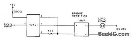
Ordinary 1-A bridge is used with H74C1 optoisolatorto pass full current to 25-W lamp when logic inρut goes low (to around,so full 5 V is applied to light source in optoisolator).-D. D. Mickle, Practical Computer Projects, 73 Magazine, Jan. 1978, p 92-93. (View)
View full Circuit Diagram | Comments | Reading(864)
10_LED_BAR_GRAPH_INDICATOR_CIRCUIT
Published:2009/7/13 4:43:00 Author:May
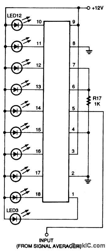
The solid-state level indicator consists of a string of 10 LEDs in one package. With a low-level signal input, all LEDs are off. As the signal increases, more LEDs light up, until finally all10 are turned on to indicate the maximum level. The heart of the circuit shown in this figure is the National Semiconductor LM3915. The LM3915 contains a precision voltage reference, resistor divider chain, and 10 comparators to drive the LEDs. This IC also contains current-limiting circuitry that limits the brightness of the LEDs without the need for separate resistors, and logic to select either a bar graph or a moving-dot display. (View)
View full Circuit Diagram | Comments | Reading(1209)
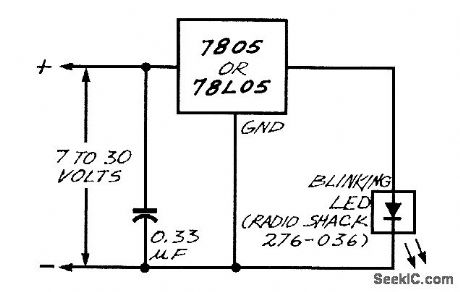
CONSTANT_BRIGHTNESS_LED_CIRCUIT
Published:2009/7/13 4:36:00 Author:May
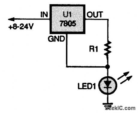
This setup ensures that the LED will glow with equal brightness as long as the input voltage remains between 8 and 24 V. R=5/I, where I=desired LED current. (View)
View full Circuit Diagram | Comments | Reading(910)
BAR_GRAPH_DISPLAY_CIRCUIT
Published:2009/7/13 4:36:00 Author:May
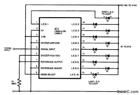
This shows how an LM3914 or LM3915 is connected for 9- to separate LEDs or part of an integral display module. (View)
View full Circuit Diagram | Comments | Reading(1647)
LARGE_LED_DISPLAY
Published:2009/7/13 4:35:00 Author:May
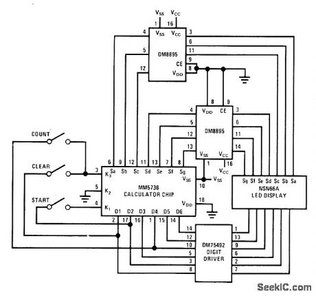
National MM5736 calculator chip is used with DM8895 segment driver that can be mask-programmed to source several values of current in range from 5 to 17 mA per segment of LED display, permitting use of fairly large display. Display current comes from VCC supply terminal of DM8895 rather than from calculator chip. Combination serves as 6-decade counter driving 6-digit display. -M. Watts, Calculator Chip Makes a Counter, Na-tional Semiconductor, Santa Clara, CA, 1974, AN-112, p 3. (View)
View full Circuit Diagram | Comments | Reading(1554)
CMOS_LOGIC_CONTROL_OF_300_W_LAMP
Published:2009/7/13 4:28:00 Author:May
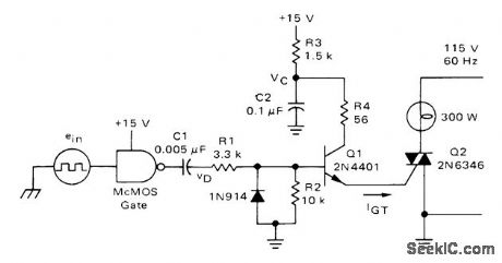
Storage capacitor C2 in interface transistor circuit for typical CMOS gate charges to full +15 V supply voltage in time determined by R3 and C2, after which al is fired by positive-going differentiated pulse derived from input square wave. C2 then dumps its charge through R4 and C1, to fire triac C2 and energize AC load. For maximum load power, triac should be fired early in conduction angle. With 1-kHz input square wave, output power is over 98% of maximum possible.-A. Pshaenich, Interface Techniques Between Industrial Logic and Power Devices, Motorola, Phoenix, AZ, 1975, AN-712A, p 13. (View)
View full Circuit Diagram | Comments | Reading(952)
| Pages:37/72 At 202122232425262728293031323334353637383940Under 20 |
Circuit Categories
power supply circuit
Amplifier Circuit
Basic Circuit
LED and Light Circuit
Sensor Circuit
Signal Processing
Electrical Equipment Circuit
Control Circuit
Remote Control Circuit
A/D-D/A Converter Circuit
Audio Circuit
Measuring and Test Circuit
Communication Circuit
Computer-Related Circuit
555 Circuit
Automotive Circuit
Repairing Circuit