
LED and Light Circuit
Index 30
MAX7302 White LED driver circuit diagram
Published:2011/8/25 20:51:00 Author:Lucas | Keyword: White LED driver
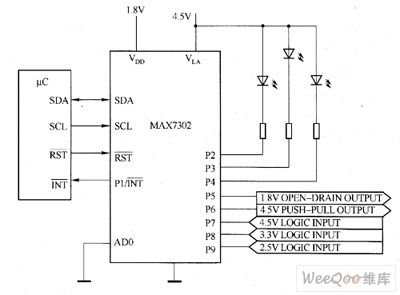
MAX7302's main technical characteristics are as follow. ① 1.62 ~ 5.5V I / O port level conversion power (ULA). ② Power supply voltage is 1.62 ~ 3.6V. ③ 9-way independent configured GPIO ports. ④ 25mA (max) port outputs sink current (the maximum ground current is 100mA). ⑤ The independent 11-stage PWM brightness control with 15-stage flash output control in output end, and 1kHz PWM cycle provides a flicker-free white LED brightness control. ⑥ Input overvoltage protection is up to 5.5V (ULA). ⑦ oscillator input and output can cascade multiple devices. ⑧ I / O port can be configured as logic gates (CLA).
(View)
View full Circuit Diagram | Comments | Reading(1041)
Dance hall strobe light circuit diagram
Published:2011/8/29 2:55:00 Author:Lucas | Keyword: Dance hall, strobe light
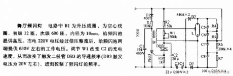
B1 in the circuit is step-up coil and hollow coil, and the primary is 12 turns with the diameter in 10mm, and it provides high voltage for strobe bubble. 220V mains voltage is voltage-multiplied and rectified to provide about 630V operating voltage at both ends of the strobe bulb. Adjusting W1 can change the charging rate of C2, thus it changes the trigger diode CB3 conduction frequency (DB3 trigger voltage is about 20V), thenit can control the strobe's frequency.
(View)
View full Circuit Diagram | Comments | Reading(1660)
LED matrix driver circuit diagram
Published:2011/9/6 4:02:00 Author:Lucas | Keyword: LED matrix driver

In this circuit, the National's MM74C908/MM74C918 dual CMOS driver is connected as the oscillator with Schmitt trigger type; R1, R2 are used to generate hysteresis, and R3, C are the inverted timing components, R4 is the down load of the first driver. The current-driving capability is greater than 250mA, so it can be used to the LED matrix or light bulbs.
(View)
View full Circuit Diagram | Comments | Reading(1420)
LED flasher circuit diagram
Published:2011/9/6 4:07:00 Author:Lucas | Keyword: LED flasher
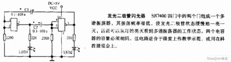
The two gates of SN7400 four gates form a multivibrator, of which oscillation frequency is very low, so the LED is turned on and off slowly, then you can see the multivibrator working condition from the lamp light turning on and off. The capacity of two capacitors must be the same. This circuit is suitable for teaching demonstration in the classroom, or in science and technology exhibition.
(View)
View full Circuit Diagram | Comments | Reading(1115)
Inverting dual flasher circuit diagram
Published:2011/9/6 4:13:00 Author:Lucas | Keyword: Inverting dual flasher
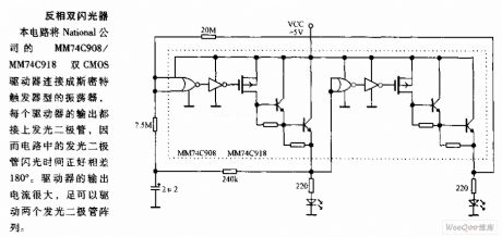
In this circuit, the National's MM74C908/MM74C918 dual CMOS driver is connected as Schmitt trigger type oscillator, and the output of each driver is connected to LED, so the flashing time of the circuit just has the difference in 180 degree. Driver's output current is high enough to drive the array with two light-emitting diodes.
(View)
View full Circuit Diagram | Comments | Reading(1055)
MAX1912 white LED driver circuit diagram
Published:2011/8/29 3:46:00 Author:Lucas | Keyword: white LED driver
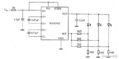
White LED power supply provides a sufficiently high output voltage, and the white LED connected in parallel is added the same current. If all the connected white LEDs in parallel has the same current, then all the white LEDs will have the same color coordinates. Maxim's MAX1912 charge pump with current control can achieve this goal. The circuit using MAX1912 to drive 3 parallel LEDs is shown as the gigure, MAX1912 charge pump has a large range, and it can increase the input voltage to 1.5 times.
MAX1912contains thecharge pumpand the current control circuit, and the charge pump provides sufficient voltage for the white LED driver.
(View)
View full Circuit Diagram | Comments | Reading(942)
MAX8631X white LED driver circuit diagram
Published:2011/8/29 3:38:00 Author:Lucas | Keyword: white LED driver
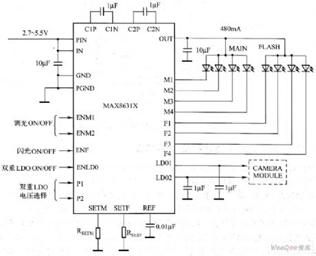
MAX8631X charge pump's main technical features are as follow. ① It can drive eight white LEDs. ② 30mA drive current is used for backlight. ③ 400mA total drive current is used for the flash. ④ two built-in low noise 200mA LDO. ⑤ It can maintain the 94% highest conversion efficiency and the 85% average conversion efficiency in the effective lithium-ion battery supply voltage range (η = PLED / PABT). ⑥ 0.2% current matching accuracy. ⑦ It has adaptive 1x mode, 1.5x mode, 2-fold pressure mode switching function. ⑧ It has flexible brightness control. ⑨It has single, serial-pulse interface (32).
(View)
View full Circuit Diagram | Comments | Reading(1121)
MAX8630Y / MAX8630Z white LED driver circuit diagram
Published:2011/8/29 3:27:00 Author:Lucas | Keyword: white LED driver
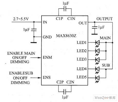
MAX8630Y/MAX8630Z charge pump's main technical features are as follow. ①It can maintain the 93% highest conversion efficiency and the 85% average conversion efficiency (η = PLED / PBAT) in the effective lithium-ion battery supply voltage range. ② 1% current matching accuracy. ③ The total drive current is up to 125mA. ④It has adaptive 1x mode, 1.5x mode switching function. ⑤ The single, burst dimming (MAX8630Z). ⑥The main screen and sub-screen has the separate opening and closing control and brightness adjustment. ⑦ linear regulator rating: full value, 31/32, 30/32, 1 / 32. ⑧ direct PWM dimming (MAX8630Y).
(View)
View full Circuit Diagram | Comments | Reading(905)
MAX1595 white LED driver circuit diagram
Published:2011/8/29 3:41:00 Author:Lucas | Keyword: white LED driver
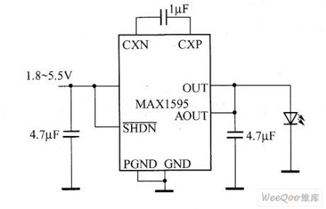
Its unique control structure allows the input voltage boost or buck converter to maintain a stable output voltage. MAX1595 charge pump's main technical characteristics are as follow. ① It requires only three external ceramic capacitors. ② It does not need inductance. ③The output current is up to 125mA. ④ The stable output voltage accuracy is ± 3%. ⑤ 1MHz switching frequency. ⑥ 1.8 ~ 5.5V input voltage range. ⑦ 220pA quiescent current. ⑧ 0.1μA shutdown current. ⑨ In shutdown mode, the load can be disconnected.
(View)
View full Circuit Diagram | Comments | Reading(1085)
Circuit diagram of driving 60 pieces of 20mA constant current LED
Published:2011/9/6 22:47:00 Author:Vicky | Keyword: 20mA constant current LED

Picture 1 shows the 6 channels of LT3598, and the channels are used to drive the 60 pieces of LED. The current of each channel of LED is set at 20mA. Pin CTRL and pin PWM take responsibility of providing simulating dimming function and digital dimming function respectively. True color PWM dimming offers constant LED color and a dimming proportion of 3000/1. Picture 2 shows ±0.5% typical current-matching accuracy between channels of LED. It generates consistent light distribution, which is very important in application in large-scale backlight.
(View)
View full Circuit Diagram | Comments | Reading(3861)
LED judgement with battery
Published:2011/8/26 3:02:00 Author:Jessie | Keyword: LED judgement , battery
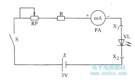
View full Circuit Diagram | Comments | Reading(773)
The circuit that can drive 3 parallel LEDs
Published:2011/8/23 22:07:00 Author:Borg | Keyword: parallel LEDs
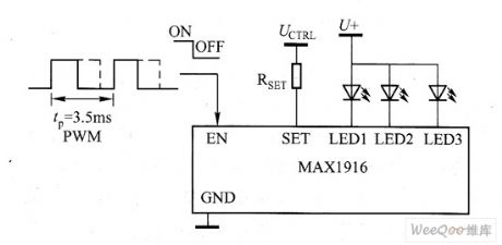
In the figured MAX1916 application circuit, a single external resistor (RSET) can be used to set the current value of each LED, and the simple brightness control (dimming function) can be fulfilled by adding wide modulation signals on the pin (EN) of the IC. By using the method of setting the LED current with the resistor RSET, little PCB space is occupied, in this method, in addition to MAX1916(6 little 6-pin SOT23 packages) and several external capacitors, only an external resistor is needed. (View)
View full Circuit Diagram | Comments | Reading(899)
The LED circuit driven by the regulated electric charge pump
Published:2011/8/21 21:38:00 Author: | Keyword: electric charge pump, LED
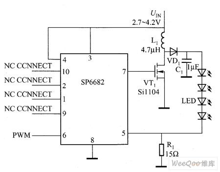
SP6682 regulated electric charge pump drive LED circuit is shown in the figure. SP6682 includes an internal 500KhZ oscillator, which is used to drive the pump capacitance normally and double the input voltage. In the figure, the circuit is not adopting with the pump capacitor, but adding the oscillator output on the 7-pin and driving VT conduction and breakdown. VT1, L1, VD1 and C1 compose a booster regulator, which can raise the voltage on the two poles of C. When the voltage surpasses the LED forward voltage drop, the current is starting to run.
(View)
View full Circuit Diagram | Comments | Reading(1012)
The circuit of controlling the LED dimmer by changing LED forward current
Published:2011/8/23 22:07:00 Author:Borg | Keyword: LED dimmer, LED forward current
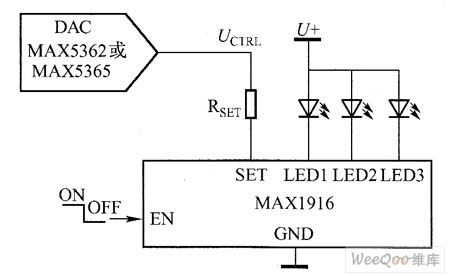
Either MAX5362 with I2C connector or MAX5365 with SP1 can provide with 32-stage brightness adjustment, see as the figure. As the forward current may affect the color coordinates, so the LED white light changes with the change of the brightness, but the same forward current will makes every LED glow the same light. The circuit of controlling the LED dimmer by changing LED forward current is shown in the figure.
Figure The circuit of controlling the LED dimmer by changing LED forward current
(View)
View full Circuit Diagram | Comments | Reading(924)
A highly concentrated pump dual-display white light LED drive circuit
Published:2011/8/23 22:07:00 Author:Borg | Keyword: dual-display, LED drive, pump
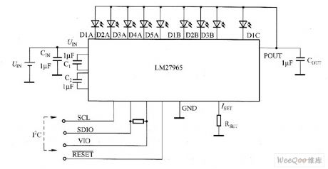
The driving pin of LM27965 dual-display white light LED drive is divided into 3 independent control banks. The first can be equipped with 4~5 white light LED, which is used to provide back light for the large screen; the second can be equipped with 2~3 white light LED, which is used to provide light for smaller affiliated display; the other controls the white light LED drive independently, which is used to drive the indicator or general LED. LM27965 is a connector which is compatible with I2C which allows the LED brightness of each team to be controlled independently.
(View)
View full Circuit Diagram | Comments | Reading(732)
A low-noise, frequency-fixed drive white light LED circuit
Published:2011/8/23 22:08:00 Author:Borg | Keyword: low-noise, frequency-fixed, white light LED
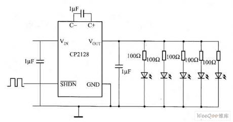
CP2128 is a low-noise, frequency-fixed booster DC/DC converter, under the condition that the voltage is 2.7~4.5V, the device is outputting a voltage os 5V, its max output current can reach 100mA. Cp2128 needs very few external elements, so it is suitable for micro and batter-powered conditions. CP2128 can reduce the output and input drift from zero to full load. CP2128 has the over-heat protection function, which can afford the continuous UOUT ground connection.
(View)
View full Circuit Diagram | Comments | Reading(811)
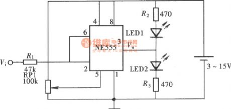
The glowing display logic pen composed of NE555 circuit
Published:2011/8/13 2:08:00 Author:qqtang | Keyword: display logic pen, NE555
View full Circuit Diagram | Comments | Reading(945)
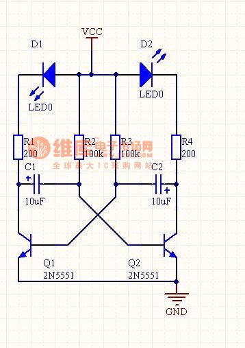
The LED flashing circuit
Published:2011/8/13 2:10:00 Author:qqtang | Keyword: LED flashing circuit
View full Circuit Diagram | Comments | Reading(1317)
Light-operated moth-killing lamp
Published:2011/8/11 20:53:00 Author:Ecco | Keyword: Light-operated , moth-killing lamp
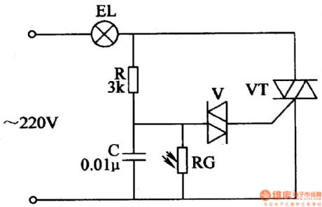
The light-operated moth-killing lamp circuit is composed of the Triac VT, two-way trigger diode V, photosensitive resistor RG, resistor R, capacitor C, and EL lamp, and it is shown in Figure 4-43. In the daytime, RG is the low resistance state (less than 5kΩ) which is affected by light exposure, and C can not be charged as being shorted by RG, V and VT can not turn on, EL does not shine. In the night, RG is in high-impedance state (greater than 1MΩ) and oc is charged normally, KL lit. R select the lW metal film resistor. RG chooses MG45 series of photosensitive resistor. V selects the DB3 or 2CTS2 two-way trigger diode.
(View)
View full Circuit Diagram | Comments | Reading(1409)
Sound, light dual control delay light circuit diagram 1
Published:2011/8/22 3:16:00 Author:Ecco | Keyword: Sound , light , dual control , delay light
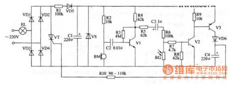
The sound, light dual control delay light circuit is composed of the power supply circuit, voice circuit, light control circuit and time delay control switch circuit, and it is shown as below. In the circuit, power supply circuit is composed of the light EL, diodes VD1-VD5, resistor R1, capacitor C1 and Zener diode VS; voice circuit is composed of the microphone BM, resistors R2-R4, transistor V1 and capacitor C2; light control circuit is composed of the photosensitive resistor RG, resistors R6 and R9 and transistor V2; delay electronic switching circuit is composed of the transistors V2, V3, diode VD6, capacitor C4, resistors R10 and R8, thyristor VT.
(View)
View full Circuit Diagram | Comments | Reading(1362)
| Pages:30/72 At 202122232425262728293031323334353637383940Under 20 |
Circuit Categories
power supply circuit
Amplifier Circuit
Basic Circuit
LED and Light Circuit
Sensor Circuit
Signal Processing
Electrical Equipment Circuit
Control Circuit
Remote Control Circuit
A/D-D/A Converter Circuit
Audio Circuit
Measuring and Test Circuit
Communication Circuit
Computer-Related Circuit
555 Circuit
Automotive Circuit
Repairing Circuit