
LED and Light Circuit
Index 16
LED Chaser
Published:2012/10/29 1:14:00 Author:muriel | Keyword: LED Chaser
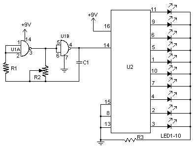
View full Circuit Diagram | Comments | Reading(1667)
LED FLASHER NEEDS ONLY 1.5 VOLTS
Published:2012/10/29 1:13:00 Author:muriel | Keyword: LED FLASHER, 1.5 VOLTS
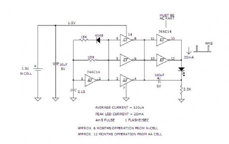
View full Circuit Diagram | Comments | Reading(1359)
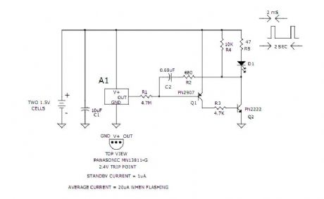
1.5V LED Flasher Oscillator
Published:2012/10/29 1:12:00 Author:muriel | Keyword: 1.5V, LED Flasher Oscillator

View full Circuit Diagram | Comments | Reading(1228)
3v Low Battery Voltage Flasher Circuit
Published:2012/10/29 1:06:00 Author:muriel | Keyword: 3v , Low Battery Voltage, Flasher Circuit
View full Circuit Diagram | Comments | Reading(1274)
1.5V LED FLASHER VERSION B
Published:2012/10/29 1:06:00 Author:muriel | Keyword: 1.5V , LED FLASHER

View full Circuit Diagram | Comments | Reading(1874)
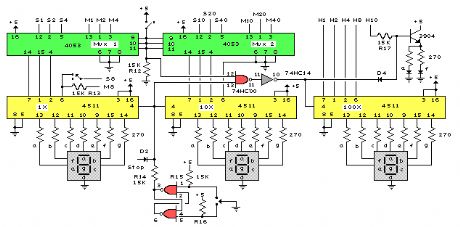
10 -point LED level display circuit with 2 blocks of BA6104 5-bit LED level meter driver integrated circuits
Published:2012/10/28 22:04:00 Author:Ecco | Keyword: 10 -point, LED , level display , 2 blocks , 5-bit , LED level meter , driver integrated circuit

Regulation IC1's pin 7 Vref can light L1 ~ L5 in IC1; Regulation IC2's pin 7 Vref can light L1 ~ L5 in IC2, and the lighting voltage is 2 times of IC1, luminous order is from L1 ~ L5 of IC1 to L1 ~ L5 of IC2.
(View)
View full Circuit Diagram | Comments | Reading(2046)
Pinewood Derby Finish Line Lamps
Published:2012/10/24 0:56:00 Author:muriel | Keyword: Pinewood Derby, Finish Line, Lamps
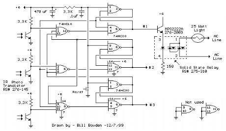
The finish line circuit below detects the first of three cars to cross the line and illuminates a 25 watt 120 VAC lamp indicating the winning lane. Three photo transistors are used which can be embedded into the track with a light shining down onto the finish line so that as the car crosses over the sensor, the light is blocked, activating the relay and lighting the lamp for the appropriate track. The light source should be an incandescent type, florescent lights may not work due to low infra-red content. The circuit was tested using a 100 watt incandescent light fixture about 3 feet above the photo transistors.
The photo transistors are connected so that a logic low (0 volts) normally appears at the input to a NAND gate and as a car crosses the line blocking light to the transistor the logic level will move high (+6 volts). The resulting logic low level from the output of the gate (3 input NAND) is fed to a SET/RESET latch made from two dual input NAND gates (1/2 of a 74HC00) the (logic high) output of which controls the MPS2222A buffer transistor and solid state relay. The inverted output of the latch (logic low) is connected back to the remaining two (3 input NAND gate) inputs locking them out. Two extra 74HC00 gates are not used and should have their inputs (pins 9,10,12,13) connected to ground to avoid possible oscillation. The circuit is reset with a momentary push button connected to the reset side of each latch. The reset button may need to be pressed after power is first applied. Components for the circuit may be obtained from Radio Shack, however the RSU numbers may need to be special ordered or obtained from another source. The 74HC00 and 74HC10 are CMOS parts and should be handled carefully to avoid possible damage from static electricity. You may want to use IC sockets so the wiring can be completed before the ICs are inserted into the sockets. You can briefly touch a grounded surface (computer chassis or other metal ground surface) just before handling CMOS circuits to reduce the possibility of damage from static electricity. (View)
View full Circuit Diagram | Comments | Reading(1219)
Game Show Indicator Lights (Who's First)
Published:2012/10/24 0:55:00 Author:muriel | Keyword: Game Show, Indicator Lights
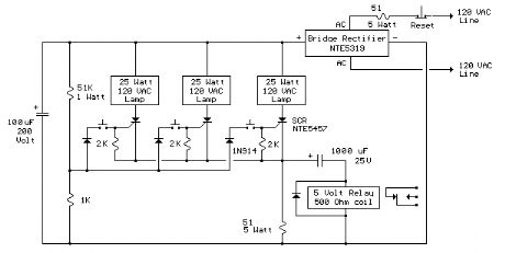
The circuit below turns on a light corresponding to the first of several buttons pressed in a Who's First game. Three stages are shown but the circuit can be extended to include any number of buttons and lamps.
Three SCRs (silicon controlled rectifiers) are connected with a common cathode resistor (50 ohm) so that when any SCR conducts, the voltage on the cathodes will rise about 7 volts above the voltage at the junction of the 51K and 1K ohm resistors and prevent triggering of a second SCR. When all lamps are off, and a button is pressed, the corresponding SCR is triggered due to the voltage at the divider junction being higher than the cathode. Once triggered, the SCR will remain conducting until current is interrupted by the reset switch. Or, you can just turn the power off and back on.
A 50 ohm, 5 watt resistor was selected to produce a 10 volt drop at 200 mA when a single 25 watt lamp comes on. Higher wattage lamps would require a lower value resistor, and visa versa. For example to use 60 watt lamps and maintain the 10 volt drop, the peak current would be 60/160 = 375 mA and the resistance would be E/I = 10/.375 or about 27 ohms at 3.75 watts. The SCRs are Sensitive Gate' types which trigger on about 200 uA and the gate current is around 1.5 mA when the first button is pressed. The 1N914 diodes in series with the buttons gates are used to prevent a reverse voltage on the gate when a button is pressed after an SCR is conducting. The two 51 ohm resistors will be fairly large in physical size (compared to a 1/4 watt size) and should be rated for 5 watts of power or more. Use caution and do not touch any components while the circuit is connected to the AC line. (View)
View full Circuit Diagram | Comments | Reading(1575)
120VAC Lamp Chaser
Published:2012/10/24 0:54:00 Author:muriel | Keyword: 120VAC , Lamp Chaser

This circuit is basically the same as the 10 channel LED sequencer with the addition of solid state relays to control the AC lamps. The relay shown in the diagram is a Radio Shack 3 amp unit (part no. 275-310) that requires 1.2 volts DC to activate. No current spec was given but I assume it needs just a few milliamps to light the internal LED. A 360 ohm resistor is shown which would limit the current to 17 mA using a 9 volt supply. I tested the circuit using a solid state relay (of unknown type) which required only 1.5 mA at 3 volts but operates up to 30 volts DC and a much higher current. The chaser circuit can be expanded up to 10 channels with additional relays and driver transistors. The 4017 decade counter reset line (pin 15) is connected to the fifth count (pin 10) so that the lamps sequence from 1 to 4 and then repeat. For additional stages the reset pin would be connected to a higher count. (View)
View full Circuit Diagram | Comments | Reading(1429)
Flashing Neons (NE-2 / NE-51)
Published:2012/10/24 0:52:00 Author:muriel | Keyword: Flashing Neons , NE-2 , NE-51
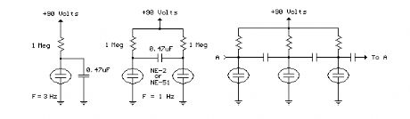
In this circuit, one, two or three neon indicator bulbs can be made to flash in sequence at rates determined by the R and C values. In the single stage circuit, using one lamp, the capacitor charges through the resistor until the ionization potential of the neon is reached (about 70 volts) and then discharges quickly through the lamp until the voltage falls below what is needed to sustain the lamp which is approximately 45 volts. The cycle then repeats at a rate of about 3 Hz for values shown. Smaller R or C values increase frequency, larger values decrease frequency. All capacitors should be the non-polarized variety with a 100 volt or more rating. For more than 3 stages, the lamps may need to be matched for similar turn-on voltages. (View)
View full Circuit Diagram | Comments | Reading(1088)
Varying brightness AC lamp
Published:2012/10/22 21:59:00 Author:muriel | Keyword: Varying brightness, AC lamp
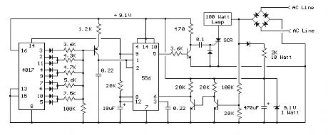
In this circuit, an SCR is used to slowly vary the intensity of a 120 volt light bulb by controlling the time that the AC line voltage is applied to the lamp during each half cycle. Caution: The circuit is directly connected to the AC power line and should be placed inside an enclosure that will prevent direct contact with any of the components. To avoid electrical shock, do not touch any part of the circuit while it is connected to the AC power line. A 2K, 10 watt power resistor is used to drop the line voltage down to 9 volts DC. This resistor will dissipate about 7 watts and needs some ventilation. Operation: A couple NPN transistors are used to detect the beginning of each half cycle and trigger a delay timer which in turn triggers the SCR at the end of the delay time. The delay time is established by a current source which is controlled by a 4017 decade counter. The first count (pin 3) sets the current to a minimum which corresponds to about 7 milliseconds of delay, or most of the half cycle time so that the lamp is almost off. Full brightness is obtained on the sixth count (pin 1) which is not connected so that the current will be maximum and provide a minimum delay and trigger the SCR near the beginning of the cycle. The remaining 8 counts increment the brightness 4 steps up and 4 steps down between maximum and minimum. Each step up or down provides about twice or half the power, so that the intensity appears to change linearly. The brightness of each step can be adjusted with the 4 resistors (4.3K, 4.7K, 5.6K, 7.5K) connected to the counter outputs.
The circuit has been built by Don Warkentien (WODEW) who suggsted adding a small 47uF capacitor from ground to the junction of the current source transistor (PNP) to reduce the digital stepping effect so the lamp will brighten and fade in a smoother fashion. The value of this capacitor will depend on the 4017 counting rate, a faster rate would require a smaller capacitor. (View)
View full Circuit Diagram | Comments | Reading(1814)
120 VAC Lamp Dimmer
Published:2012/10/22 21:59:00 Author:muriel | Keyword: 120 VAC , Lamp Dimmer
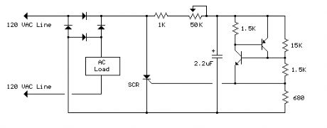
The full wave phase control circuit below was found in a RCA power circuits book from 1969. The load is placed in series with the AC line and the four diodes provide a full wave rectified voltage to the anode of a SCR. Two small signal transistors are connected in a switch configuration so that when the voltage on the 2.2uF capacitor reaches about 8 volts, the transistors will switch on and discharge the capacitor through the SCR gate causing it to begin conducting. The time delay from the beginning of each half cycle to the point where the SCR switches on is controlled by the 50K resistor which adjusts the time required for the 2uF capacitor to charge to 8 volts. As the resistance is reduced, the time is reduced and the SCR will conduct earlier during each half cycle which applies a greater average voltage across the load. With the resistance set to minimum the SCR will trigger when the voltage rises to about 40 volts or 15 degrees into the cycle. To compensate for component tollerances, the 15K resistor can be adjusted slightly so that the output voltage is near zero when the 50K pot is set to maximum. Increasing the 15K resistor will reduce the setting of the 50K pot for minimum output and visa versa. Be careful not to touch the circuit while it is connected to the AC line. (View)
View full Circuit Diagram | Comments | Reading(1367)
Photo Electric Street Light
Published:2012/10/22 21:48:00 Author:muriel | Keyword: Photo, Electric, Street Light
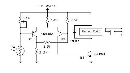
This is basically a Schmitt Trigger circuit which receives input from a cadmium sulfide photo cell and controls a relay that can be used to switch off and on a street lamp at dawn and dusk. I have built the circuit with a 120 ohm/12 volt relay and monitored performance using a lamp dimmer, but did not connect the relay to an outside light.
The photo cell should be shielded from the lamp to prevent feedback and is usually mounted above the light on top of a reflector and pointed upward at the sky so the lamp light does not strike the photo cell and switch off the lamp.
The photo cell is wired in series with a potentiometer so the voltage at the junction (and base of transistor) can be adjusted to about half the supply, at the desired ambient light level. The two PNP transistors are connected with a common emitter resistor for positive feedback so as one transistor turns on, the other will turn off, and visa versa. Under dark conditions, the photo cell resistance will be higher than the potentiometer producing a voltage at Q1 that is higher than the base voltage at Q2 which causes Q2 to conduct and activate the relay.
The switching points are about 8 volts and 4 volts using the resistor values shown but could be brought closer together by using a lower value for the 7.5K resistor. 3.3K would move the levels to about 3.5 and 5.5 for a range of 2 volts instead of 4 so the relay turns on and off closer to the same ambient light level. The potentiometer would need to be readjusted so that the voltage is around 4.5 at the desired ambient condition.
(View)
View full Circuit Diagram | Comments | Reading(1432)
LED Traffic Lights
Published:2012/10/22 21:47:00 Author:muriel | Keyword: LED, Traffic Lights
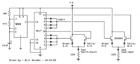
The LED traffic Light circuit controls 6 LEDs (red, yellow and green) for both north/south directions and east/west directions. The timing sequence is generated using a CMOS 4017 decade counter and a 555 timer. Counter outputs 1 through 4 are wire ORed using 4 diodes so that the (Red - North/South) and (Green - East/West) LEDs will be on during the first four counts. The fifth count (pin 10) illuminates (Yellow - East/West) and (Red - North/South). Counts 6 through 9 are also wire ORed using diodes to control (Red - East/West) and (Green - North/South). Count 10 (pin 11) controls (Red - East/West) and (Yellow - North/South). The time period for the red and green lamps will be 4 times longer than for the yellow and the complete cycle time can be adjusted with the 47K resistor. The eight 1N914 diodes could be subsituted with a dual 4 input OR gate (CD4072). (View)
View full Circuit Diagram | Comments | Reading(1960)
Line Powered White LEDs
Published:2012/10/22 21:46:00 Author:muriel | Keyword: Line Powered , White LEDs
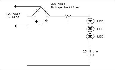
The LED circuit below is an example of using 25 white LEDs in series connected to the 120VAC line. It can be modified for more or less LEDs by adjusting the resistor value. The exact resistance will depend on the particular LEDs used. But working out the resistor value is a bit complicated since current will not continously flow through the resistor.
In operation, the output of the bridge rectifier will be about 120 DC RMS or 170 volts peak. If we use 25 white LEDs with a forward voltage of 3 volts each, the total LED voltage will be 75 volts. The peak resistor voltage will be 170- 75 or 95 volts but the resistor voltage will not be continous since the input must rise above 75 before any current flows. This (dead time) represents about 26 degrees of the 90 degree half wave rectified cycle, (asin) 75/170 = (asin) .44 = 26 degrees. This means the resistor will conduct during 90-26 = 64 degrees, or about 71 percent of the time.
Next we can work out the peak LED current to determine the resistor value. If the LED current is 20mA RMS, the peak current will be 20*1.414 or 28mA. But since the duty cycle is only 71 percent, we need to adjust this figure up to 28/0.71 = 39mA. So, the resistor value should be 95/.039 = 2436 ohms (2.4K) and the power rating will be .02^2 *2400= .96 watts. A two watt size is recommended.
Now this circuit can also be built using 2 diodes and resistor as shown in the lower drawing. The second diode in parallel with the LEDs is used to avoid a reverse voltage on the LEDs in case the other diode leaks a little bit. It may not be necessary but I thought it was a good idea.
Working out the resistor value is similar to the other example and comes out to about half the value of the full wave version, or about 1.2K at 1 watt in this case. But the peak LED current will be twice as much or about 78mA. This is probably not too much, but you may want to look up the maximum current for short duty cycles for the LEDs used and insure 79mA doesn't exceed the spec. (View)
View full Circuit Diagram | Comments | Reading(1817)
AC Line powered LEDs
Published:2012/10/22 21:46:00 Author:muriel | Keyword: AC Line, powered LEDs
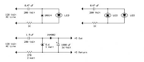
The circuit below illustrates powering a LED (or two) from the 120 volt AC line using a capacitor to drop the voltage and a small resistor to limit the inrush current. Since the capacitor must pass current in both directions, a small diode is connected in parallel with the LED to provide a path for the negative half cycle and also to limit the reverse voltage across the LED. A second LED with the polarity reversed may be subsituted for the diode, or a tri-color LED could be used which would appear orange with alternating current. The circuit is fairly efficient and draws only about a half watt from the line. The resistor value (1K / half watt) was chosen to limit the worst case inrush current to about 150 mA which will drop to less than 30 mA in a millisecond as the capacitor charges. This appears to be a safe value, I have switched the circuit on and off many times without damage to the LED. The 0.47 uF capacitor has a reactance of 5600 ohms at 60 cycles so the LED current is about 20 mA half wave, or 10 mA average. A larger capacitor will increase the current and a smaller one will reduce it. The capacitor must be a non-polarized type with a voltage rating of 200 volts or more.
The lower circuit is an example of obtaining a low regulated voltage from the AC line. The zener diode serves as a regulator and also provides a path for the negative half cycle current when it conducts in the forward direction. In this example the output voltage is about 5 volts and will provide over 30 milliamps with about 300 millivolts of ripple. Use caution when operating any circuits connected directly to the AC line. (View)
View full Circuit Diagram | Comments | Reading(2274)
1.5 Volt LED Flashers
Published:2012/10/22 21:45:00 Author:muriel | Keyword: 1.5 Volt, LED Flashers
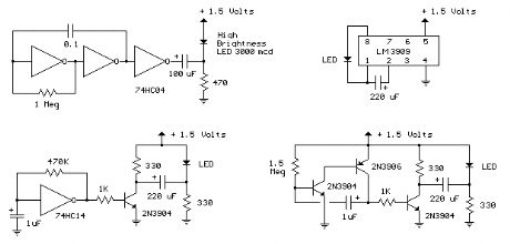
The LED flasher circuits below operate on a single 1.5 volt battery. The circuit on the upper right uses the popular LM3909 LED flasher IC and requires only a timing capacitor and LED.
The top left circuit, designed by Andre De-Guerin illustrates using a 100uF capacitor to double the battery voltage to obtain 3 volts for the LED. Two sections of a 74HC04 hex inverter are used as a squarewave oscillator that establishes the flash rate while a third section is used as a buffer that charges the capacitor in series with a 470 ohm resistor while the buffer output is at +1.5 volts. When the buffer output switches to ground (zero volts) the charged capacitor is placed in series with the LED and the battery which supplies enough voltage to illuminate the LED. The LED current is approximately 3 mA, so a high brightness LED is recommended.
In the other two circuits, the same voltage doubling principle is used with the addition of a transistor to allow the capacitor to discharge faster and supply a greater current (about 40 mA peak). A larger capacitor (1000uF) in series with a 33 ohm resistor would increase the flash duration to about 50mS. The discrete 3 transistor circuit at the lower right would need a resistor (about 5K) in series with the 1uF capacitor to widen the pulse width. (View)
View full Circuit Diagram | Comments | Reading(1352)
Three-way Kala 0K lighting rendering circuit (HL3033)
Published:2012/10/22 2:42:00 Author:Ecco | Keyword: Three-way, Kala 0K, lighting rendering

As shown in the figure, it is a Kala 0K lighting rendering controller with audio voltage controlled ASIC HL3033 produced by Wuxi love Silicon microelectronics company. It has a three-way outputs, the flowing speed of the light will change with the loudness of concert, and it can powerfully render concert atmosphere and beautify the indoor environment, so it is very suitable for home Kala 0K concert.
(View)
View full Circuit Diagram | Comments | Reading(1123)
Clock Display Circuit
Published:2012/10/22 1:21:00 Author:muriel | Keyword: Clock Display Circuit
View full Circuit Diagram | Comments | Reading(1895)
40 LED Bicycle Light
Published:2012/10/22 1:16:00 Author:muriel | Keyword: 40 LED, Bicycle Light
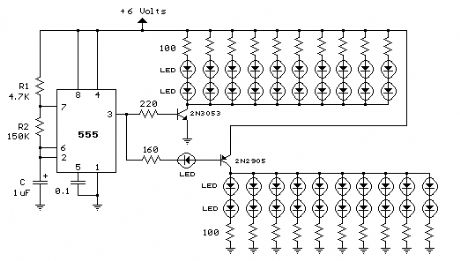
The 555 circuit below is a flashing bicycle light powered with four C,D or AA cells (6 volts). Two sets of 20 LEDs will alternately flash at approximately 4.7 cycles per second using RC values shown (4.7K for R1, 150K for R2 and a 1uF capacitor). Time intervals for the two lamps are about 107 milliseconds (T1, upper LEDs) and 104 milliseconds (T2 lower LEDs). Two transistors are used to provide additional current beyond the 200 mA limit of the 555 timer. A single LED is placed in series with the base of the PNP transistor so that the lower 20 LEDs turn off when the 555 output goes high during the T1 time interval. The high output level of the 555 timer is 1.7 volts less than the supply voltage. Adding the LED increases the forward voltage required for the PNP transistor to about 2.7 volts so that the 1.7 volt difference from supply to the output is insufficient to turn on the transistor. Each LED is supplied with about 20 mA of current for a total of 220 mA. The circuit should work with additional LEDs up to about 40 for each group, or 81 total. The circuit will also work with fewer LEDs so it could be assembled and tested with just 5 LEDs (two groups of two plus one) before adding the others. (View)
View full Circuit Diagram | Comments | Reading(2211)
| Pages:16/72 1234567891011121314151617181920Under 20 |
Circuit Categories
power supply circuit
Amplifier Circuit
Basic Circuit
LED and Light Circuit
Sensor Circuit
Signal Processing
Electrical Equipment Circuit
Control Circuit
Remote Control Circuit
A/D-D/A Converter Circuit
Audio Circuit
Measuring and Test Circuit
Communication Circuit
Computer-Related Circuit
555 Circuit
Automotive Circuit
Repairing Circuit