
LED and Light Circuit
Index 17
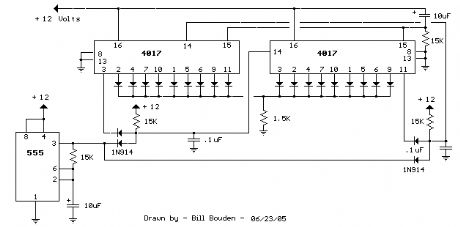
25 Light Sequencer using Xmas lamps
Published:2012/10/22 1:15:00 Author:muriel | Keyword: 25 Light Sequencer, Xmas lamps
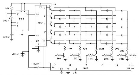
This circuit is same as the above setup to drive 25 small Xmas lights. The lights operate at about 200mA and 3 volts. The supply voltage is set to 5 volts and the 4017 counter output will drop about a volt using the 2N3053 transistors. The voltage on the emitters of the rows transistors will be about 0.7 volts less than the base so the lamp voltage will be about 3 volts. You can adjust the supply voltage for the desired current if necessary. It works the same way as the LED version but you need diodes in series with each light. Most any small diode rated at 500mA or more should work. I used 1N4001 diodes. Various NPN transistors can be used, I tried 2N2219A and 2N3053. The 2N3053 worked out better with a higher gain than the 2N2219A, but either one should work. (View)
View full Circuit Diagram | Comments | Reading(2552)
60 Light Sequencer using a Matrix
Published:2012/10/22 1:14:00 Author:muriel | Keyword: 60 Light Sequencer, Matrix
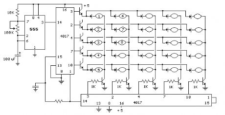
The circuit below illustrates using a 10x10 matrix to sequence up to 100 LEDs with just three ICs and 20 transistors. The two 4017 decade counters control the 10 rows and 10 columns so that one LED is selected depending on the output of the decade counters.
The LED circuit is drawn showing 25 LEDs and 10 transistors but can be expanded up to a 100 by using sucessive stages of the 4017 counters.
For example, to expand the circuit to 60 LEDs for displaying minutes or seconds of a clock, the rows counter could be reset from pin 12 (carry out) rather than pin 1 as shown, and the columns counter will be reset from pin 5 rather than pin 1 as shown. And then add transistors to pins 1,5,6,9,and 11 of the rows counter and pin 1 of the columns counter. Take a look at the 10 Stage LED Sequencer for a listing of all the connections of the 4017 decade counter. (View)
View full Circuit Diagram | Comments | Reading(2885)
50 Hertz LED Clock Timebase
Published:2012/10/22 1:13:00 Author:muriel | Keyword: 50 Hertz , LED Clock , Timebase
View full Circuit Diagram | Comments | Reading(1189)
72 LED Clock
Published:2012/10/22 1:11:00 Author:muriel | Keyword: 72 , LED Clock
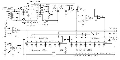
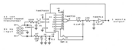
In the circuit below, 60 individual LEDs are used to indicate the minutes of a clock and 12 LEDs indicate hours. The power supply and time base circuitry is the same as described in the 28 LED clock circuit above. The minutes section of the clock is comprised of eight 74HCT164 shift registers cascaded so that a single bit can be recirculated through the 60 stages indicating the appropriate minute of the hour. Only two of the minutes shift registers are shown connected to 16 LEDs. Pin 13 of each register connects to pin 1 of the next for 7 registers. Pin 6 of the 8th register should connect back to pin 1 of the first register using the 47K resistor. Pins 2,9,8, 14 and 7 of all 8 minutes registers (74HC164) should be connected in parallel (pin 8 to pin 8, pin 9 to pin 9, etc.). The hours section contains two 8 bit shift registers and works the same way as the minutes to display 1 of 12 hours. Pin 9 of all 74HCT164s (hours and minutes) should be connected together. For 50 Hertz operation, the time base section of the circuit can be modified as shown in the lower drawing labeled 50 Hertz LED Clock Time Base . You will need an extra IC (74HC30) to do this since it requires decoding 7 bits of the counter instead of 4. The two dual input NAND gates (1/2 74HC00) that are not used in the 50 Hertz modification should have their inputs connected to ground.
When power is applied, a single 1 bit is loaded into the first stage of both the minutes and hours registers. To accomplish this, a momentary low reset signal is sent to all the registers (at pin 9) and also a NAND gate to lock out any clock transitions at pin 8 of the minutes registers. At the same time, a high level is applied to the data input lines of both minutes and hours registers at pin 1. A single positive going clock pulse (at pin 8) is generated at the end of the reset signal which loads a high level into the first stage of the minutes register. The rising edge of first stage output at pin 3 advances the hours (at pin 8) and a single bit is also loaded into the hours register. Power should remain off for about 3 seconds or more before being re-applied to allow the filter and timing capacitors to discharge. A 1K bleeder resistor is used across the 1000uF filter capacitor to discharge it in about 3 seconds. The timing diagram illustrates the power-on sequence where T1 is the time power is applied and beginning of the reset signal, T2 is the end of the reset signal, T3 is the clock signal to move a high level at pin 1 into the first register, T4 is the end of the data signal. The time delay from T2 to T3 is exaggerated in the drawing and is actually a very short time of just the propagation delay through the inverter and gate.
Two momentary push buttons can be used to set the correct time. The button labeled M will increment the minutes slowly and the one labled H much faster so that the hours increment slowly. The hours should be set first, followed by minutes. (View)
View full Circuit Diagram | Comments | Reading(1827)
Automobile Interior Lights Fader
Published:2012/10/22 1:08:00 Author:muriel | Keyword: Automobile Interior, Lights Fader
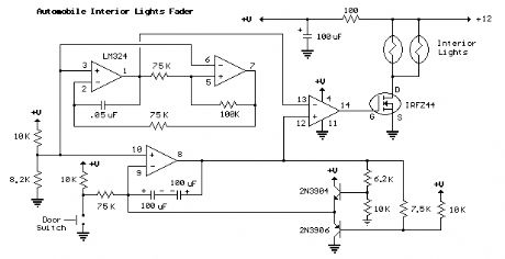
The circuit is based around the LM324 low power opamp which draws around 3mA of current, so it won't bother the battery if left connected for extended periods.
The top two opamps (pins 1,2,3 and 5,6,7) form a triangle wave oscillator running at about 700Hz while the lower opamp (pins 8,9,10) produces a linear, 5 second ramp, that moves up or down depending on the position of the door switch. The two transistors and associated resistors serve to limit the ramp voltage to slightly more and less than the upper and lower limits of the triangle waveform. These two signals (700 hZ. triangle wave and 5 second ramp) are applied to the inputs of the 4th opamp (pins 12,13,14) that serves as a voltage comparator and generates a varying duty cycle square wave that controls the IRFZ44 MOSFET and lamp brightness. The 5 second fade time can be adjusted with the 75K resistor connected to the door switch. A larger value will increase the time and a smaller value will speed it up.
When the door switch is closed (car door open) the voltage on pin 8 slowly rises above the negative peaks of the triangle wave producing a short duty cycle output and a dim light. As the ramp moves farther positive, a greater percentage of the triangle wave will be lower than the ramp voltage producing a wider pulse and brighter light. This process continues until the ramp is 100% above the positive peaks of the triangle wave and the output is maximum. When the door switch is open, the reverse action takes place and the lamps slowly fade out.
The IRFZ44 shouldn't require a heat sink if the total load is 50 watts or less but the temperature of the MOSFET should be monitored to insure it doesn't overheat. The on-state resistance is only 0.028 ohms so that 4 amps of current (48 watts) is only around 100mW. For larger loads, a small heat sink can be added to keep the MOSFET cool. (View)
View full Circuit Diagram | Comments | Reading(1466)
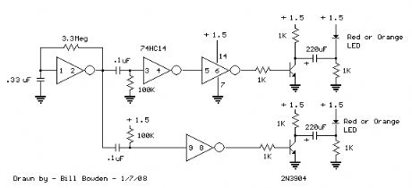
Fading Red Eyes
Published:2012/10/22 1:07:00 Author:muriel | Keyword: Fading, Red Eyes
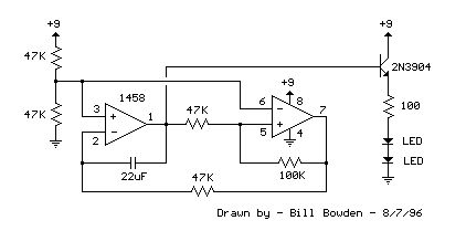
This circuit is used to slowly illuminate and fade a pair of redLEDs (light emitting diodes). The fading LEDs could be installedas 'eyes' in a small pumpkin or skull as a Halloween attraction,or mounted in a Christmas tree ornament. Or, they might be usedas a fancy power indicator for your computer, microwave oven,stereo system, TV, or other appliance.In operation, a linear 3 volt (peak to peak) ramping waveform isgenerated at pin 1 of the LM1458 IC and buffered with an emitter followertransistor stage. The 22uF capacitor and 47K resistor connected topin 2 establish the frequency which is about 0.5 Hz. You can make therate adjustable by using a 100K potentiometer in place of the 47Kresistor at pin 2.The circuit consists of two operational amplifiers (opamps),one producing a slow rising and falling voltage from about 3 volts to6 volts, and the other (on the right) is used as a voltage comparator,the output of which supplies a alternating voltage switching between2 and 7 volts to charge and discharge the capacitor with a constantcurrent. (View)
View full Circuit Diagram | Comments | Reading(2013)
Two Transistor LED Flasher
Published:2012/10/22 1:06:00 Author:muriel | Keyword: Two Transistor, LED Flasher
View full Circuit Diagram | Comments | Reading(1479)
18 Stage LED Sequencer
Published:2012/10/22 1:05:00 Author:muriel | Keyword: 18 Stage, LED Sequencer
The question sometimes comes up of how to cascade 4017 decade counters for more than 10 sequencial stages. The LED sequencer below shows a possible solution using a few extra parts.
When power is applied, the 15K resistor and 10uF cap at pin 15 will reset the counters to the zero count where pin 3 is at +12 and all other outputs are at zero. The 2 diodes (1n914) and 15 resistor form a AND gate so the clock pulse will be passed to the right side counter when the sequence starts. When the right counter reaches the 10th count, pin 11 will move high enabling the AND gate on the right to pass the clock pulse to the left side counter. As the left side counter advances, pin 3 will be low so that clock pulses cannot advance the right counter. When the left counter turns over and pin 3 again moves high, the sequence will repeat. Thus we get 18 total counts, 9 from the first counter, and 9 from the second.
Note that the 4017 counter will not deliver much current, and so the LED current is set to about 6mA using a 1.5K resistor in series. For more current, you could use transistors on each output as shown in the drawing above, (10 Channel LED Sequencer). But some of the newer bright LEDs are fairly bright at 6mA. (View)
View full Circuit Diagram | Comments | Reading(2710)
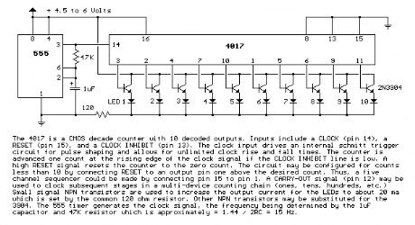
10 Channel LED Sequencer
Published:2012/10/22 1:04:00 Author:muriel | Keyword: 10 Channel, LED Sequencer
View full Circuit Diagram | Comments | Reading(1955)
Expandable 16 Stage LED Sequencer
Published:2012/10/22 1:03:00 Author:muriel | Keyword: Expandable , 16 Stage, LED Sequencer
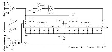
The circuit below uses a hex Schmitt Trigger inverter (74HC14) and two 8 bit Serial-In/Parallel-Out shift registers (74HCT164 or 74HC164) to sequence 16 LEDs. The circuit can be expanded to greater lengths by cascading additional shift registers and connecting the 8th output (pin 13) to the data input (pin 1) of the succeeding stage. A Schmitt trigger oscillator (74HC14 pin 1 and 2) produces the clock signal for the shift registers, the rate being approximately 1/RC. Two additional Schmitt Trigger stages are used to reset and load the registers when power is turned on. Timing is not critical, however the output at pin 8 of the Schmitt Trigger must remain high during the first LOW to HIGH clock transition at pin 8 of the registers, and must return low before the second rising edge to load a single bit. If the clock rate is increased, the length of the signal at pin 9 of the Schmitt Trigger should be reduced proportionally to avoid loading more than one bit. The HCT devices will normally provide about 4 mA (source or sink) from each output but can supply greater currents (possibly 25 mA) if only one output is loaded. The common 150 ohm resistor restricts the current below 25 mA using a 6 volt power source. If the circuit is operated with two or more LEDs on at the same time, resistors may be needed in series with each LED to avoid exceeding the maximum total output current for each IC of 25 mA. For greater brightness, individual buffer transistors can be used as shown in the 10 stage LED sequencer on this same page. (View)
View full Circuit Diagram | Comments | Reading(2247)
Interfacing 5 volt CMOS to 12 volt/ 25 Watt Loads
Published:2012/10/22 1:03:00 Author:muriel | Keyword: Interfacing , 5 volt , CMOS to 12 volt/ 25 Watt, Loads
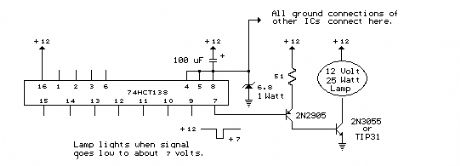
The circuit below is designed to be used with the bi-directional lamp sequencer shown above on this same page. Two additional transistors are used to increase the current from the 74HCT138 decoder to control 12 volt 25 watt lamps. A 6.8 volt/1 watt zener diode is used in series with the ground connection of all the CMOS ICs (74HC14, CD4516 and 74HC138s) so that the total voltage across the CMOS devices will be about 5.2 volts and the outputs will move from +12 to about +7 when selected. The 2N2905/PNP transistor stage is connected as an emitter follower which provides a high impedance to the decoder output and supplies about 80 mA of current to the base of the 2N3055 NPN power transistor which then supplies 2 or more amps to the 12 volt lamp. The voltage across the PNP transistor will be about 7 volts when it is turned on and the heat dissapation will be about 0.6 watts. That should't require a heat sink if several lamps are sequencing but it may get quite warm if the circuit is idle on a single output. The 2N3055 power transistor operates as a switch and drops very little voltage (less than 0.5) when conducting, and will not require a heat sink. Other transistors may be substituted such as the TIP29 or TIP31 for the 2N3055 and most any medium power (500mA) PNP for the 2N2905. (View)
View full Circuit Diagram | Comments | Reading(1020)
16 Stage Bi-Directional LED Sequencer
Published:2012/10/22 1:02:00 Author:muriel | Keyword: 16 Stage , Bi-Directional , LED Sequencer
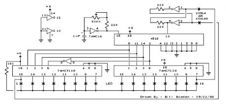
The bi-directional sequencer uses a 4 bit binary up/down counter (CD4516) and two 1 of 8 line decoders (74HC138 or 74HCT138) to generate the popular Night Rider display. A Schmitt Trigger oscillator provides the clock signal for the counter and the rate can be adjusted with the 500K pot. Two additional Schmitt Trigger inverters are used as a SET/RESET latch to control the counting direction (up or down). Be sure to use the 74HC14 and not the 74HCT14, the 74HCT14 may not work due to the low TTL input trigger level. When the highest count is reached (1111) the low output at pin 7 sets the latch so that the UP/DOWN input to the counter goes low and causes the counter to begin decrementing. When the lowest count is reached (0000) the latch is reset (high) so that the counter will begin incrementing on the next rising clock edge. The three lowest counter bits (Q0, Q1, Q2) are connected to both decoders in parallel and the highest bit Q3 is used to select the appropriate decoder. The circuit can be used to drive 12 volt/25 watt lamps with the addition of two transistors per lamp as shown below in the section below titled Interfacing 5 volt CMOS to 12 volt loads (View)
View full Circuit Diagram | Comments | Reading(1271)
Descrete Multistage Light Sequencer
Published:2012/10/22 1:01:00 Author:muriel | Keyword: Descrete Multistage , Light Sequencer
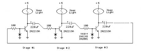
The drawing below illustrates a multistage light sequencer using descrete parts and no integrated circuits. The idea is not new and I hear a similar circuit was developed about 40 years ago using germanium transistors. The idea is to connect the lights so that as one turns off it causes the next to turn on, and so forth. This is accomplished with a large capacitor between each stage that charges when a stage turns off and supplies base current to the next transistor, thus turning it on. Any number of stages can be used and the drawing below illustrates 3 small Christmas lights running at about 5 volts and 200mA. The circuit may need to be manually started when power is applied. To start it, connect a momentary short across any one of the capacitors and then remove the short. You could use a manual push button to do this.
Detailed operation:
Assume the circuit doesn't start when power is applied amd all lights are off and all three capacitors are charged to about 5 volts. We connect a jumper across the 220uF capacitor on the left which discharges the capacitor and turns on the 2nd stage transistor and corresponding light. When the jumper is removed, the capacitor will start charging through the base of the stage 2 transistor and stage 1 light. This causes the stage 2 transistor to remain on while the capacitor continues to charge. At the same time, the capacitor connecting stage 2 and 3 will discharge through the 100 ohm resistor and diode and stage 2 transistor. When the capacitor charging current falls below what is needed to keep stage 2 turned on, the transistor and light will turn off causing the voltage at the collector of the stage 2 transistor to rise to 5 volts. Since the capacitor connecting stage 2 and 3 has discharged and the voltage rises at the collector of stage 2, the capacitor from stage 2 and 3 will charge causing the 3rd stage to turn on and the cycle repeats for sucessive stages 4,5,6,7.... and back to 1. The sequence rate is determined by the capacitor and resistor values (220uF and 100 ohms in this case), load current (200mA in this case), and current gain of the particular transistor used. This arrangement runs at about 120 complete cycles per minute for 3 lights, or about 167mS per light. Faster or slower rates can be obtained with different capacitor values. (View)
View full Circuit Diagram | Comments | Reading(1294)
1.5 volt dual LED flasher (runs one year)
Published:2012/10/22 1:01:00 Author:muriel | Keyword: 1.5 volt, dual LED , flasher, runs one year
This 1.5 volt led fasher runs more than a year on a single 'd cell and alternately flashes 2 LEDs at about a 1 second rate. The circuit employs a 74HC14 CMOS hex inverter that will operate at very low voltages (less than 1 volt). One section is used as a squarewave oscillator (pins 1 and 2), while the others are wired to produce a short 10mS pulse on alternate edges of the square wave so the LEDs will alternate back and forth. The output sections each use a capacitor charge pump to increase the voltage for the LEDs. The circuit draws an average current of 800uA from the 'D' battery and the LED peak current is about 40mA with a fresh battery and drops to about 10mA as the battery voltage falls to 1.1 volts. The capacity of a alkaline 'D' cell is about 12 amp hours with a cutoff voltage of 1.1 so the circuit should run about 12/.0008 = 15000 hours or maybe 625 days, but I haven't verified that yet. (View)
View full Circuit Diagram | Comments | Reading(1571)
Sunrise Lamp
Published:2012/10/18 22:45:00 Author:muriel | Keyword: Sunrise Lamp
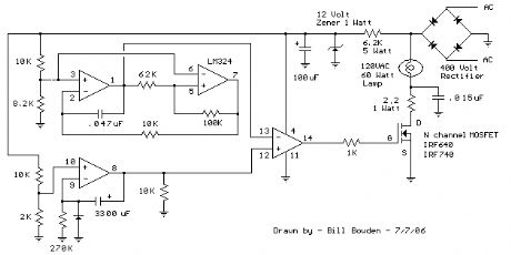
In this circuit, a 120VAC lamp is slowly illuminated over a approximate 20 minute period. The bridge rectifier supplies 120 DC to the MOSFET and 60 watt lamp. A 6.2K, 5 watt resistor and zener diode is used to drop the voltage to 12 volts DC for the circuit power. The bridge rectifier should be rated at 200 volts and 5 amps or more. In operation, a 700 Hz triangle waveform is generated at pin 1 of the LM324 and a slow rising voltage is obtained at pin 8. These two signals are compared at pins 12 and 13 to produce a varying duty cycle rectangular waveform at pin 14, which controls the MOSFET and brightness of the 60 watt lamp. When power is applied, the lamp will start to illuminate within a minute or so, and will slowly brighten to full intensity in about 20 minutes. You can make that longer or shorter with adjustments to the 270K resistor at pin 9. The 2.2 ohm resistor and .015uF cap connected to the lamp serve to supress RFI. The diode at pin 9 and 10K resistor on pin 8 are used to discharge the 3300uF cap when power is removed. Power should be off for a few minutes before re-starting.
Caution: This circuit is connected directly to the AC line and presents a hazard if any part is touched while connected to the line. Use caution and do not touch any parts while the circuit is connected to the AC line. You may want to use a 9 volt battery connected across the 12 volt zener to check the basic operation. The DC voltage at pins 1,2,3,5,6,7 will all be around 4.3 volts if the circuit is working correctly. If the DC voltages are all correct, you can use a variac to slowly apply the full line voltage and check for proper operation. (View)
View full Circuit Diagram | Comments | Reading(1235)
Touch Activated Light
Published:2012/10/18 2:07:00 Author:muriel | Keyword: Touch, Activated Light
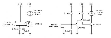
The circuits below light a 20 watt lamp when the contacts are touched and the skin resistance is about 2 Megs or less. The circuit on the left uses a power MOSFET which turns on when the voltage between the source and gate is around 6 volts. The gate of the MOSFET draws no current so the voltage on the gate will be half the supply voltage or 6 volts when the resistance across the touch contacts is equal to the fixed resistance (2 Megs) between the source and gate.
The circuit on the right uses three bipolar transistors to accomplish the same result with the touch contact referenced to the negative or ground end of the supply. Since the base of a bipolar transistor draws current and the current gain is usually less than 200, three transistors are needed to raise the microamp current level through the touch contacts to a couple amps needed by the light. For additional current, the lamp could be replaced with a 12 volt relay and diode across the coil. (View)
View full Circuit Diagram | Comments | Reading(1204)
Two 5:00 LED display driver circuits with HA7666P/TA7667P
Published:2012/10/14 20:22:00 Author:Ecco | Keyword: Two, 5:00, LED display, driver
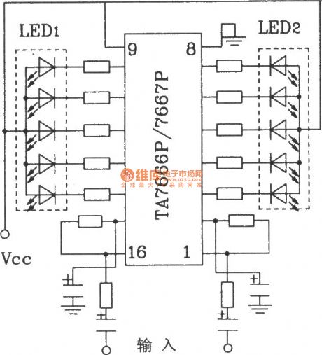
This circuit input signal is analog voltage input, and the scale display can use 10:00 display model TLR8101 or TLG8101.
(View)
View full Circuit Diagram | Comments | Reading(2364)
Bad Light Bulb Indicator
Published:2012/10/11 21:27:00 Author:muriel | Keyword: Bad Light, Bulb Indicator

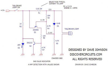


This request came from a Discover Circuits visitor. He wanted to turn on a LED indicator light whenever a circuit detected a burned out tail/brake light on a car or truck. The circuit shown below uses a transistor switch, to detect current flowing through a low value resistor. If current is flowing to a light bulb, the circuit shunts current around a LED light, keeping the LED turned off. If there is no current detected, the LED turns on. The circuit should operate from 6v to 24v.
The shunt resistor needs to be selected, so the current flowing to one light bulb generates at least 0.1 volts across the resistor. Since most turn signals illuminate two light bulbs at one time, this circuit may not detect a single burned out bulb, until the tail lights are turned on or until the car brakes are applied.
(View)
View full Circuit Diagram | Comments | Reading(2630)
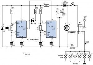
12V Dimmer circuit
Published:2012/10/11 21:09:00 Author:muriel | Keyword: 12V, Dimmer

A dimmer is quite unusual in a caravan or on a boat. Here we describe how you can make one. So if you would like to be able to adjust the mood when you’re entertaining friends and acquaintances, then this circuit enables you to do so. Designing a dimmer for 12 V is tricky business.The dimmers you find in your home are designed to operate from an AC voltage and use this AC voltage as a fundamental characteristic for their operation. Because we now have to start with 12 V DC, we have to generate the AC voltage ourselves. We also have to keep in mind that we’re dealing with battery powered equipment and have to be frugal with energy.
The circuit that we finally arrived at can easily drive 6 lamps of 10 W each. Fewer are also possible, of course. In any case, the total current has to be smaller than 10 A. L1 and S1 can be adapted to suit a smaller current, if required. Note that the whole circuit will also work from 6 V. IC1 is a dual timer. You could also use the old faithful NE556, but it draws a little more current. IC1a is wired as an astable multivibrator with a frequency of 180 Hz. IC1b is configured as a monostable and is triggered, via D2, from the positive edge at the output of IC1a.
The length of the pulse that now appears at the output of IC1b is dependant on the position of P1. IC1b will be reset whenever the output of IC1a goes low, independent of the pulse duration, set with P1, R4 and C4. This guarantees that the dimming is smooth, even when the brightness is set to maximum.
12Volt dimmer circuit diagram
The output of IC1b (pin 9) drives the gate of MOSFET T1. When the duration of the pulses at the gate increases, the average time that the MOSFET is in conduction will also increase. In this way the brightness of the lamps is controlled. T1 conducts about 96 % of the time when the brightness is set to maximum. In this configuration, this can never be 100 %, because the 4 % of the time that the FET does not conduct is necessary to charge C6.
If the FET were to conduct with 100 % duty cycle, the power supply for the circuit would be effectively short-circuited. C6 allows the circuit to ride through the conduction period of the FET. D1 ensures that the charge cannot leak away via the FET during the ‘on’ period.
In the schematic, an IRL2203N is indicated for T1, but in principle you could use just about any power transistor (for example, BUK455, BUZ10, BUZ11 or BUZ100). The IRL2203 does however, have a very low ‘on’ resistance (RDS ON) of only 7 mΩ and can switch 12-V loads up to 5 A without a heatsink. If you choose a different MOSFET (with higher RDS ON) or use the circuit in a 6-V system then you will likely need a heatsink.
Using the IRL2203N with six lamps rated 12 V / 10 W, T1 dissipates only 170 mW. At 6 V and 10 A this becomes 680 mW. The circuit itself consumes about 0.35 mA at maximum brightness and about 1.25 mA at minimum.
12 Volt dimmer pcb layout
(View)
View full Circuit Diagram | Comments | Reading(3573)
The application circuit of single flashing light-emitting diode
Published:2012/10/10 21:39:00 Author:Ecco | Keyword: application, single , flashing light-emitting diode
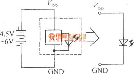
Flashing light-emitting diode operating frequency is only a few Hertz, and it is easy to attract attention, so it can be widely used in a variety of alarm circuits, such as temperature, liquid level and voltage -limit alarm circuit.
(View)
View full Circuit Diagram | Comments | Reading(1094)
| Pages:17/72 1234567891011121314151617181920Under 20 |
Circuit Categories
power supply circuit
Amplifier Circuit
Basic Circuit
LED and Light Circuit
Sensor Circuit
Signal Processing
Electrical Equipment Circuit
Control Circuit
Remote Control Circuit
A/D-D/A Converter Circuit
Audio Circuit
Measuring and Test Circuit
Communication Circuit
Computer-Related Circuit
555 Circuit
Automotive Circuit
Repairing Circuit