
power supply circuit
Index 42
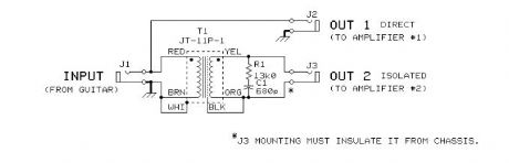
2-Way Passive Guitar Splitter
Published:2012/10/24 1:16:00 Author:muriel | Keyword: 2-Way , Passive, Guitar Splitter
View full Circuit Diagram | Comments | Reading(4667)
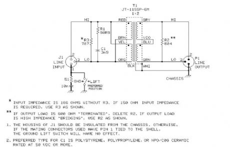
150 Ohm Line to 600 Ohm Load Application
Published:2012/10/24 1:16:00 Author:muriel | Keyword: 150 Ohm , Line to 600 Ohm , Load Application
View full Circuit Diagram | Comments | Reading(1207)
Batteries charger & PSU - ideal for digital cameras
Published:2012/10/24 1:13:00 Author:muriel | Keyword: Batteries charger, PSU
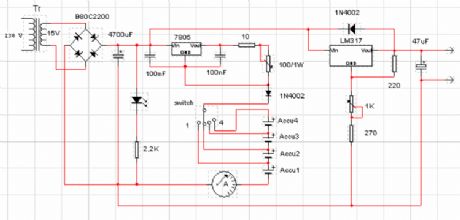
This circuit was created for digital cameras. It's known the digital cameras have considerable power consumption. For example my camera Minolta E223 requires approximately 800 mA. In practice a mains power supply or high capacity NiMH accumulators (batteries) can satisfy this demand.
This circuit consists of two parts, charger and adapter. The transformer, rectifier bridge and buffer condensator are common. Adapter is quite simply its main part is an adjustable voltage regulator LM 317 according to usual setting. Output is a suitable for camera jack plug. Voltage can be adjusted in range 2-9 V.In the charger circuit a 7805 fixed voltage regulator works as current generator assured constant current during charging. This charging current can be adjusted with the 100 /1W potentiometer in range about 50-300 mA indicated by a small current measuring instrument. From one to four batteries can be charged simultaneously. The switch must be set according to number of batteries, and charging current of batteries given by manufacturer must be adjusted. This circuit doesn't measure charging time and charging condition of batteries. Manufacturers give charging time, usually 14-16 h. I solved this problem with a simply, cheap mechanical mains timer. I think its accuracy is sufficient. (View)
View full Circuit Diagram | Comments | Reading(1239)
Constant Current Battery Charger
Published:2012/10/24 0:54:00 Author:muriel | Keyword: Constant Current, Battery Charger
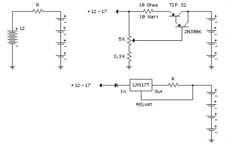
A simple method of charging a battery from a higher voltage battery is shown in the circuit below to the left. Only one resistor is needed to set the desired charging current and is calculated by dividing the difference in battery voltages by the charge current. So, for example if 4 high capacity (4000 mA hour) ni-cads are to be charged at 300 mA from a 12 volt battery, the resistor needed would be 12-(4*1.25)/0.3 = 23.3 ohms, or 22 ohms which is the nearest standard value. The power rating for the resistor is figured from the square of the current times the resistance or (0.3)^2 * 22 = 2 watts which is a standard value but close to the limit, so a 5 watt or greater value is recommended.
The circuit below (right) illustrates a constant current source used to charge a group of 1 to 10 ni-cad batteries. A 5K pot and 3.3K resistor are used to set the voltage at the emitter of the TIP 32 which establishes the current through the output and 10 ohm resistor. The emitter voltage will be about 1.5 volts above the voltage at the wiper of the pot, or about 1/2 the supply voltage when the wiper is in the downward most position. In the fully upward position the transistors will be turned off and the current will be close to zero. This yields a current range of 0 to (0.5*input)/10 or 0 to 850 milliamps using a 17 volt input. This produces about 7 watts of heat dissipation at maximum current for the 10 ohm resistor, so a 10 watt or greater rating is needed. The TIP 32 transistor will also dissipate about 7 watts if the output is shorted and needs to be mounted on a heat sink. If more than 4 cells are connected, the maximum current available will decrease and limits the current setting to about 100 milliamps for 10 cells. The usual charge rate for high capacity (4AH) 'D' cells is 300 to 400 milliamps for 14 hours and 100 milliamps for (1.2AH) 'C' or 'D' cells. For small 9 volt batteries the charge rate is 7 milliamps for 14 hours which would be difficult to set and probably unstable, so you could reduce the range to 0-20 mA by using a 750 ohm resistor in place of the 10. The charge current can be set by connecting a milliamp meter across the output (with the batteries disconnected) and then adjusting the control to the desired current, or by monitoring the voltage across the 10 ohm resistor (1 volt = 100 mA) or (1 volt = 1.33 mA using a 750 ohm resistor). The current control should be set to minimum (wiper in uppermost position) before power is applied, and then adjusted to the desired current.
The circuit (lower right) illustrates using a LM317 variable voltage regulator as a constant current source. The voltage between the adjustment terminal and the output terminal is always 1.25 volts, so by connecting the adjustment terminal to the load and placing a resistor (R) between the load and the output terminal, a constant current of 1.25/R is established. Thus we need a 12 ohm resistor (R) to get 100mA of charge current and a 1.2 ohm, 2 watt resistor for 1 amp of current. A diode is used in series with the input to prevent the batteries from applying a reverse voltage to the regulator if the power is turned off while the batteries are still connected. It's probably a good idea to remove the batteries before turning off the power. (View)
View full Circuit Diagram | Comments | Reading(0)
Light Activated Relay
Published:2012/10/24 0:51:00 Author:muriel | Keyword: Light Activated, Relay
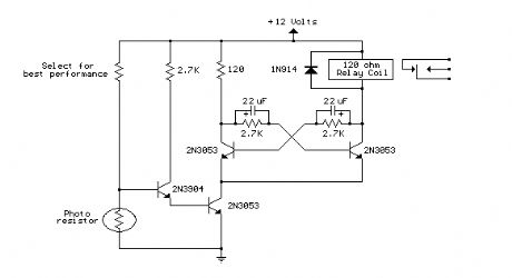
This is same circuit as above with the addition of a photo resistor to trigger the flip flop instead of a push button. The bias resistor in series with photo resistor was chosen so that sufficient voltage is present at the base of the 2N3904 to supply current to the circuit in ambient lighting conditions. The circuit should toggle when the photo resistor is hit by a flashlight beam or other fast changing light source. Slow changes in light intensity will have no effect unless the light gets too bright to maintain sufficient bias for the 2N3904. (View)
View full Circuit Diagram | Comments | Reading(1566)
Solar Cell Boost Converter
Published:2012/10/23 20:29:00 Author:muriel | Keyword: Solar Cell, Boost Converter
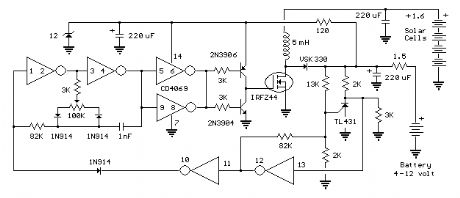
The boost converter is used to charge batteries from low voltage solar arrays. Results were obtained using 3X3 cells that deliver about 400 millivolts at 1 amp. The pictured panel array contains 20 cells in series and generates about 8 watts at 8 volts in bright sunlight and was assembled on a 12 X 16 picture frame. Efficiency of the converter measured 87% and delivers almost 600 milliamps into a 12 volt SLA battery. Efficiency drops to about 72% using 4 single cells in series (pictured above) charging the same 12 volt battery at around 70mA. The current was a little low due to a couple broken corners. A third test was made using a single cell at 0.4 volt charging a 6 volt battery, but efficiency was only about 55%. The cells were purchased from solarcells101.com in slightly damaged condition with chipped edges and a few tiny cracks, but still perform well and sell at discount. There are also many good deals on ebay. (View)
View full Circuit Diagram | Comments | Reading(1729)
DC to DC Converter
Published:2012/10/22 21:58:00 Author:muriel | Keyword: DC to DC, Converter
The circuit below is a DC to DC converter using a standard 12 VAC center tapped power transformer wired as a blocking oscillator. The circuit is not very efficient but will produce a high voltage usable for low power applications. The input battery voltage is raised by a factor of 10 across the transformer and further raised by a voltage tripler consisting of three capacitors and diodes connected to the high voltage side of the transformer. The circuit draws about 40 milliamps and should operate for about 200 hours on a couple of 'D' alkaline batteries. Higher voltages can be obtained by reducing the 4.7K bias resistor. (View)
View full Circuit Diagram | Comments | Reading(2251)
2 Watt Switching Power Supply
Published:2012/10/22 21:57:00 Author:muriel | Keyword: 2 Watt , Switching Power Supply
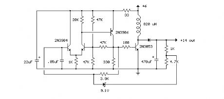
In this small switching power supply, a Schmitt trigger oscillator is used to drive a switching transistor that supplies current to a small inductor. Energy is stored in the inductor while the transistor is on, and released into the load circuit when the transistor switches off. The output voltage is dependent on the load resistance and is limited by a zener diode that stops the oscillator when the voltage reaches about 14 volts. Higher or lower voltages can be obtained by adjusting the voltage divider that feeds the zener diode. The efficiency is about 80% using a high Q inductor. (View)
View full Circuit Diagram | Comments | Reading(1095)
Variable Voltage and Current Power Supply
Published:2012/10/22 21:56:00 Author:muriel | Keyword: Variable Voltage , Current, Power Supply
Another method of using opamps to regulate a power supply is shown below. The power transformer requires an additional winding to supply the op-amps with a bipolar voltage (+/- 8 volts), and the negative voltage is also used to generate a reference voltage below ground so that the output voltage can be adjusted all the way down to 0. Current limiting is accomplished by sensing the voltage drop across a small resistor placed in series with the negative supply line. As the current increases, the voltage at the wiper of the 500 ohm pot rises until it becomes equal or slightly more positive than the voltage at the (+) input of the opamp. The opamp output then moves negative and reduces the voltage at the base of the 2N3053 transistor which in turn reduces the current to the 2N3055 pass transistor so that the current stays at a constant level even if the supply is shorted. Current limiting range is about 0 - 3 amps with components shown. The TIP32 and 2N3055 pass transistors should be mounted on suitable heat sinks and the 0.2 ohm current sensing resistor should be rated at 2 watts or more. The heat produced by the pass transistor will be the product of the difference in voltage between the input and output, and the load current. So, for example if the input voltage (at the collector of the pass transistor) is 25 and the output is adjusted for 6 volts and the load is drawing 1 amp, the heat dissipated by the pass transistor would be (25-6) * 1 = 19 watts. In the circuit below, the switch could be set to the 18 volt position to reduce the heat generated to about 12 watts. (View)
View full Circuit Diagram | Comments | Reading(1959)
Variable 3 - 24 Volt / 3 Amp Power Supply
Published:2012/10/22 21:56:00 Author:muriel | Keyword: Variable, 3 - 24 Volt, 3 Amp , Power Supply
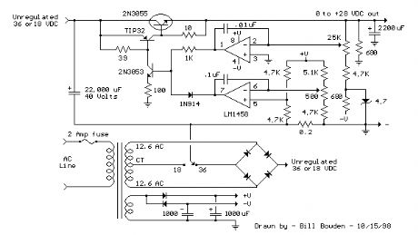
This regulated power supply can be adjusted from 3 to 25 volts and is current limited to 2 amps as shown, but may be increased to 3 amps or more by selecting a smaller current sense resistor (0.3 ohm). The 2N3055 and 2N3053 transistors should be mounted on suitable heat sinks and the current sense resistor should be rated at 3 watts or more. Voltage regulation is controlled by 1/2 of a 1558 or 1458 op-amp. The 1458 may be substituted in the circuit below, but it is recommended the supply voltage to pin 8 be limited to 30 VDC, which can be accomplished by adding a 6.2 volt zener or 5.1 K resistor in series with pin 8. The maximum DC supply voltage for the 1458 and 1558 is 36 and 44 respectively. The power transformer should be capable of the desired current while maintaining an input voltage at least 4 volts higher than the desired output, but not exceeding the maximum supply voltage of the op-amp under minimal load conditions. The power transformer shown is a center tapped 25.2 volt AC / 2 amp unit that will provide regulated outputs of 24 volts at 0.7 amps, 15 volts at 2 amps, or 6 volts at 3 amps. The 3 amp output is obtained using the center tap of the transformer with the switch in the 18 volt position. All components should be available at Radio Shack with the exception of the 1558 op-amp.
(View)
View full Circuit Diagram | Comments | Reading(1530)
Generating -5 Volts From a 9 Volt Battery
Published:2012/10/22 21:44:00 Author:muriel | Keyword: Generating, -5 Volts, 9 Volt, Battery
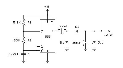
A 555 timer can be used to generate a squarewave to produce a negative voltage relative to the negative battery terminal. When the timer output at pin 3 goes positive, the series 22 uF capacitor charges through the diode (D1) to about 8 volts. When the output switches to ground, the 22 uF cap discharges through the second diode (D2) and charges the 100 uF capacitor to a negative voltage. The negative voltage can rise over several cycles to about -7 volts but is limited by the 5.1 volt zener diode which serves as a regulator. Circuit draws about 6 milliamps from the battery without the zener diode connected and about 18 milliamps connected. Output current available for the load is about 12 milliamps. An additional 5.1 volt zener and 330 ohm resistor could be used to regulate the +9 down to +5 at 12 mA if a symmetrical +/- 5 volt supply is needed. The battery drain would then be around 30 mA. (View)
View full Circuit Diagram | Comments | Reading(1092)
Capacitor Discharge Ignition Circuit (CDI)
Published:2012/10/22 1:26:00 Author:muriel | Keyword: Capacitor Discharge, Ignition Circuit (CDI)
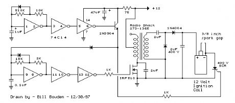
The CDI ignition circuit produces a spark from an ignition coil by discharging a capacitor across the primary of the coil. A 2uF capacitor is charged to about 340 volts and the discharge is controlled by an SCR. A Schmitt trigger oscillator (74C14) and MOSFET (IRF510) are used to drive the low voltage side of a small (120/12 volt) power transformer and a voltage doubler arrangement is used on the high voltage side to increase the capacitor voltage to about 340 volts. A similar Schmitt trigger oscillator is used to trigger the SCR about 4 times per second. The power supply is gated off during the discharge time so that the SCR will stop conducting and return to it's blocking state. The diode connected from the 3904 to pin 9 of the 74C14 causes the power supply oscillator to stop during discharge time. The circuit draws only about 200 milliamps from a 12 volt source and delivers almost twice the normal energy of a conventional ignition circuit. High voltage from the coil is about 10KV using a 3/8 inch spark gap at normal air temperature and pressure. Spark rate can be increased to possibly 10 Hertz without losing much spark intensity, but is limited by the low frequency power transformer and duty cycle of the oscillator. For faster spark rates, a higher frequency and lower impedance supply would be required. Note that the ignition coil is not grounded and presents a shock hazard on all of it's terminals. Use CAUTION when operating the circuit. An alternate method of connecting the coil is to ground the (-) terminal and relocate the capacitor between the cathode of the rectifier diode and the positive coil terminal. The SCR is then placed between ground and the +340 volt side of the capacitor. This reduces the shock hazard and is the usual configuration in automotive applications. (View)
View full Circuit Diagram | Comments | Reading(1911)
High Current Regulated Supply
Published:2012/10/19 0:57:00 Author:muriel | Keyword: High Current, Regulated Supply
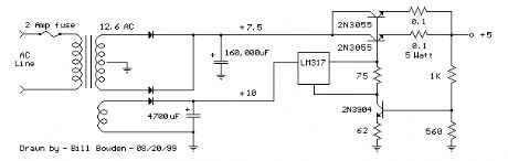
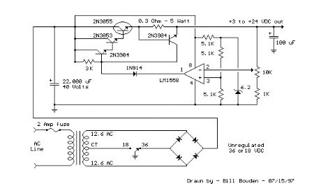
The high current regulator below uses an additional winding or a separate transformer to supply power for the LM317 regulator so that the pass transistors can operate closer to saturation and improve efficiency. For good efficiency the voltage at the collectors of the two parallel 2N3055 pass transistors should be close to the output voltage. The LM317 requires a couple extra volts on the input side, plus the emitter/base drop of the 3055s, plus whatever is lost across the (0.1 ohm) equalizing resistors (1volt at 10 amps), so a separate transformer and rectifier/filter circuit is used that is a few volts higher than the output voltage. The LM317 will provide over 1 amp of current to drive the bases of the pass transistors and assumming a gain of 10 the combination should deliver 15 amps or more. The LM317 always operates with a voltage difference of 1.2 between the output terminal and adjustment terminal and requires a minimum load of 10mA, so a 75 ohm resistor was chosen which will draw (1.2/75 = 16mA). This same current flows through the emitter resistor of the 2N3904 which produces about a 1 volt drop across the 62 ohm resistor and 1.7 volts at the base. The output voltage is set with the voltage divider (1K/560) so that 1.7 volts is applied to the 3904 base when the output is 5 volts. For 13 volt operation, the 1K resistor could be adjusted to around 3.6K. The regulator has no output short circuit protection so the output probably should be fused. (View)
View full Circuit Diagram | Comments | Reading(1410)
Simple Adjustable Voltage Source
Published:2012/10/19 0:56:00 Author:muriel | Keyword: Simple, Adjustable, Voltage Source
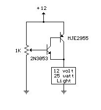
A simple but less efficient methode of controlling a DC voltage is to use a voltage divider and transistor emitter follower configuration. The figure below illustrates using a 1K pot to set the base voltage of a medium power NPN transistor. The collector of the NPN feeds the base of a larger PNP power transistor which supplies most of the current to the load. The output voltage will be about 0.7 volts below the voltage of the wiper of the 1K pot so the output can be adjusted from 0 to the full supply voltage minus 0.7 volts. Using two transistors provides a current gain of around 1000 or more so that only a couple milliamps of current is drawn from the voltage divider to supply a couple amps of current at the output. Note that this circuit is much less efficient than the 555 timer dimmer circuit using a variabe duty cycle switching approach. In the figure below, the 25 watt/ 12 volt lamp draws about 2 amps at 12 volts and 1 amp at 3 volts so that the power lost when the lamp is dim is around (12-3 volts * 1 amp) = 9 watts. A fairly large heat sink is required to prevent the PNP power transistor from overheating. The power consumed by the lamp will be only (3 volts * 1 amp) = 3 watts which gives us an efficiency factor of only 25% when the lamp is dimmed. The advantage of the circuit is simplicity, and also that it doesn't generate any RF interference as a switching regulator does. The circuit can be used as a voltage regulator if the input voltage remains constant, but it will not compensate for changes at the input as the LM317 does. (View)
View full Circuit Diagram | Comments | Reading(977)
2 Cell Lithium Ion Charger
Published:2012/10/19 0:56:00 Author:muriel | Keyword: 2 Cell, Lithium Ion Charger
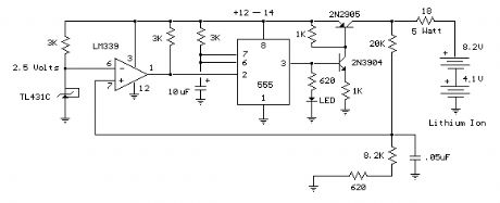
This circuit was build to charge a couple series Lithium cells (3.6 volts each, 1 Amp Hour capacity) installed in a portable transistor radio.
The charger operates by supplying a short current pulse through a series resistor and then monitoring the battery voltage to determine if another pulse is required. The current can be adjusted by changing the series resistor or adjusting the input voltage. When the battery is low, the current pulses are spaced close together so that a somewhat constant current is present. As the batteries reach full charge, the pulses are spaced farther apart and the full charge condition is indicated by the LED blinking at a slower rate.
A TL431, band gap voltage reference (2.5 volts) is used on pin 6 of the comparator so the comparator output will switch low, triggering the 555 timer when the voltage at pin 7 is less than 2.5 volts. The 555 output turns on the 2 transistors and the batteries charge for about 30 milliseconds. When the charge pulse ends, the battery voltage is measured and divided down by the combination 20K, 8.2K and 620 ohm resistors so when the battery voltage reaches 8.2 volts, the input at pin 7 of the comparator will rise slightly above 2.5 volts and the circuit will stop charging.
The circuit could be used to charge other types of batteries such as Ni-Cad, NiMh or lead acid, but the shut-off voltage will need to be adjusted by changing the 8.2K and 620 ohm resistors so that the input to the comparator remains at 2.5 volts when the terminal battery voltage is reached.
For example, to charge a 6 volt lead acid battery to a limit of 7 volts, the current through the 20K resistor will be (7-2.5)/ 20K = 225 microamps. This means the combination of the other 2 resistors (8.2K and 620) must be R=E/I = 2.5/ 225 uA = 11,111 ohms. But this is not a standard value, so you could use a 10K in series with a 1.1K, or some other values that total 11.11K
Be careful not to overcharge the batteries. I would recommend using a large capacitor in place of the battery to test the circuit and verify it shuts off at the correct voltage. (View)
View full Circuit Diagram | Comments | Reading(2645)
One or Two Cell Li-Ion Battery Charger
Published:2012/10/19 0:55:00 Author:muriel | Keyword: One or Two Cell, Li-Ion Battery Charger
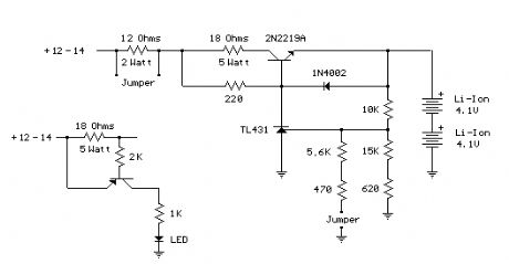
When the battery is low, the voltage at the reference pin of the TL431 will be less than 2.5 volts, causing the TL431 to switch off, increasing the transistor base voltage and charge current. Current is limited to around 300 mA by the 18 ohm resistor (2 cell setup). As the battery approaches full charge, the TL431 reference pin approaches 2.5 volts, increasing the TL431 current and reducing the transistor base voltage and charge current. Using 2 cells (8.2 volts, 1000 mAH), the current drops from 300mA to about 100mA as the charge reaches 75% of capacity in 200 minutes. Another hour is needed to bring the charge to 85% Note, the value of 4.1 rather than 4.2 was chosen for a little more margin, and less stress on the battery at full charge. From the data above, it looks like only 5% of capacity is lost. The diode prevents a reverse voltage across the e/b transistor junction in the event the power supply connections are shorted while the battery is still connected. The 220 ohm resistor was selected for about 20mA base current. The minimum transistor gain is 30, so 20mA should produce at least 600mA. The open circuit output voltage is set with a voltage divider for either 4.1 or 8.2 volts. Two jumpers are used to select the desired voltage and current limit.
For example, to charge a single Li-ion cell to 4.1 volts, the current through the 10K resistor will be (4.1-2.5)/ 10K = 160 microamps. The series combination of the other 2 resistors should total 2.5 / 160 uA = 15625 ohms. A 15K in series with 620 might be used, and the 620 adjusted to compensate for the 15K being slightly more or less. I ended up 15K and 750 since the 15K was a little low.
In the 2-cell (8.2 volt) case, two additional resistors are added in parallel with the 15625 (using the jumper) to increase the output voltage from 4.1 to 8.2. I ended up with 5.6K in series with 430 ohms. The 430 can be adjusted to get it just right.
A second jumper is used (across the 12 ohm resistor) to maintain approximately the same charge current with either single or double cell operation. Both jumpers are installed for 8.2 volt operation and removed for 4.1 volt operation. Note: The circuit board picture shows two 5 watt 12 ohm resistors. One of the resistors is out of tolerance and is actually 17 ohms.
Caution: Be careful not to set the jumpers for 8.2 volt operation while connected to a single cell (4.1 volt) battery. Use a DMM to verify the open circuit voltage is what you want before connecting the battery. (View)
View full Circuit Diagram | Comments | Reading(3624)
3.6 Volt cell phone battery meter
Published:2012/10/19 0:38:00 Author:muriel | Keyword: 3.6 Volt, cell phone , battery meter
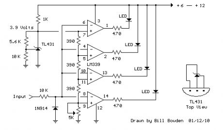
This is a similar circuit to the above and provides a 4 LED bar graph indicating the voltage of a common 3.6 volt Lithium - Ion recharable cell phone battery. The reference voltage is provided by a TL431 programmable voltage source which is set to 3.9 volts where the TL431 connects to the 1K resistor. The lower reference for the LED at pin 14 is set with the 5K adjustable resistor.
The programmed voltage of the TL431 is worked out with a voltage divider (10K 5.6K). The adjustment terminal or junction of the two resistors is always 2.5 volts. So, if we use a 10K resistor from the adjustment terminal to ground, the resistor current will be 2.5/10000 = 250uA. This same current flows through the upper resistor (5.6K) and produces a voltage drop of .00025 * 5600 = 1.4 volts. So the shunt regulated output voltage at the cathode of the TL431 will be 2.5 + 1.4, or 3.9 volts.
Working out the LED voltages, there are three 390 ohm resistors in series with another adjustable (5K) resistor at the bottom. Assuming the bottom resistor is set to 2K ohms, the total resistance is 390+390+390+2000 = 3170 ohms. So, the resistor current is the reference voltage (3.9) divided by the total resistance, or about 3.9/ (390 + 390 + 390 + 2000) equals 1.23 mA. This gives us about .00123*2000= 2.46 volts for the bottom LED, and about .00123*390 = .48 volts for each step above the bottom. So, the LEDs should light at steps of 2.46, 2.94, 3.42, and 3.9. A fully charged cell phone battery is about 4.2 volts. You can adjust the 5.6K resistor to set the top voltage higher or lower, and adjust the lower 5K resistor to set the bottom LED for the lowest voltage. But you do need a 6 to 12 volt or greater battery to power the circuit. (View)
View full Circuit Diagram | Comments | Reading(1816)
LED 12 Volt Lead Acid Battery Meter
Published:2012/10/19 0:37:00 Author:muriel | Keyword: LED, 12 Volt, Lead Acid, Battery Meter

In the circuit below, a quad voltage comparator (LM339) is used as a simple bar graph meter to indicate the charge condition of a 12 volt, lead acid battery. A 5 volt reference voltage is connected to each of the (+) inputs of the four comparators and the (-) inputs are connected to successive points along a voltage divider. The LEDs will illuminate when the voltage at the negative (-) input exceeds the reference voltage. Calibration can be done by adjusting the 2K potentiometer so that all four LEDs illuminate when the battery voltage is 12.7 volts, indicating full charge with no load on the battery. At 11.7 volts, the LEDs should be off indicating a dead battery. Each LED represents an approximate 25% change in charge condition or 300 millivolts, so that 3 LEDs indicate 75%, 2 LEDs indicate 50%, etc. The actual voltages will depend on temperature conditions and battery type, wet cell, gel cell etc. Additional information on battery maintenance can be found at: Battery Maintenance Tutorial (View)
View full Circuit Diagram | Comments | Reading(2779)
Telephone Ring Generator Using Small Power Transformer
Published:2012/10/19 0:36:00 Author:muriel | Keyword: Telephone Ring, Generator, Power Transformer
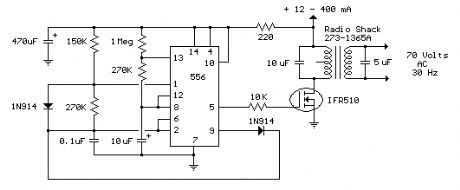
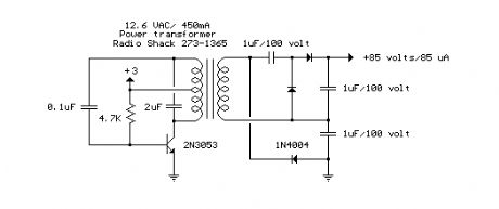
This ring generator will ring a telephone once every 10 seconds. The interval between rings can be lengthened or shortened by varying the value of the 1 Meg resistor. The 70 volt/ 30 Hz ring voltage is produced from the 120 volt side of a small 12.6 VAC power transformer (Radio Shack 273-1365). Both capacitors connected across the transformer windings are non-polarized / 100 volts. Circuit draws about 300mA from the 12 volt DC power supply during the ringing interval. (View)
View full Circuit Diagram | Comments | Reading(1762)
Telephone Ring Generator Using Switching Supply
Published:2012/10/18 22:58:00 Author:muriel | Keyword: Telephone Ring, Generator , Switching Supply
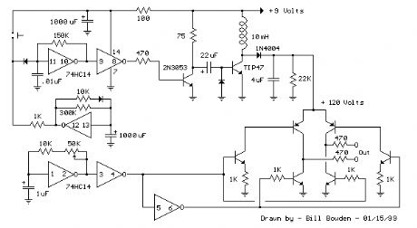
The telephone ring generator shown below generates the needed high voltage from a simple switching mode power supply (SMPS) which employs a CMOS Schmitt Trigger square wave oscillator, 10 mH inductor, high voltage switching transistor (TIP47 or other high voltage, 1 amp transistor) and a driver transistor (2N3053). The inductor should have a low DC resistance of 1.5 ohms or less. The switching supply must have a load connected to prevent the voltage from rising too high, so a 22K resistor is used across the output which limits the voltage to about 120 DC with the phone ringer disconnected and about 90 volts DC connected. The output voltage can be adjusted by changing the value of the 150K resistor between pins 10 and 11 which will alter the oscillator frequency (frequency is around 800 Hz as shown). The supply is gated on and off by a second Schmitt Trigger oscillator (pins 12/13) so that the phone rings for about 2 seconds and then the circuit idles for about a minute between rings. These times can be adjusted with the 10K and 300K resistors connected to pin 12. The push button shown is used to manually ring the phone. The 25Hz ringing frequency is generated by another Schmitt Trigger oscillator (pins 1/2) which controls the H bridge transistor output circuit. The 6 transistors in the output stage (4 NPN, 2 PNP) should be high voltage types rated at 200 volts collector to emitter or more. The ringer will only draw around 10 mA, so the output transistors can have a low current rating but must have a high voltage rating. I used TIP47s and small signal PNPs of unknown numbers that I had on hand, but other types such as NTE287 (NPN) and NTE288 (PNP) should work. Both have a 300 volt C-E rating and cost about $0.95 from mail order houses.
The two 470 ohm resistors connected to the output serve to limit the current in case the output is shorted. I never tried shorting the output to see how effective the resistors are, but I did lose a couple transistors and then decided to add the resistors. They should limit the surge to around 120 mA which should be low enough to prevent damage. The circuit draws around 250 mA when the ring signal is present so if you want to operate it from batteries, six 'D' type alkaline cells are recommended. It probably won't work with a small 9 volt battery.
(View)
View full Circuit Diagram | Comments | Reading(1893)
| Pages:42/291 At 204142434445464748495051525354555657585960Under 20 |
Circuit Categories
power supply circuit
Amplifier Circuit
Basic Circuit
LED and Light Circuit
Sensor Circuit
Signal Processing
Electrical Equipment Circuit
Control Circuit
Remote Control Circuit
A/D-D/A Converter Circuit
Audio Circuit
Measuring and Test Circuit
Communication Circuit
Computer-Related Circuit
555 Circuit
Automotive Circuit
Repairing Circuit