
power supply circuit
Index 59
DS2760 lithium-ion battery protection circuit
Published:2011/9/12 22:04:00 Author:John | Keyword: lithium-ion battery
DS2760 has a 25mΩ sense resistor inside, which can detect two-way (charging and discharging) current (but its resistance and loss are bothe extremely small). The current resolution is 0.625mA and the dynamic range is within l.8A. It isalso with current cumulative function. The voltage measurement resolution is 48mV. Its temperature measurement resolution is up to 0.125 ℃. The digital converted by the A / D converter is stored in the corresponding memory container. It is connected with the main system through a single interface, thus leading it to be able to do management and control on lithium-ion battery power supply. Therefore, it is able to read / write access and control with internal memory container.
(View)
View full Circuit Diagram | Comments | Reading(2567)
Circuit Diagram of Solar-energy Nickel-cadmium Cell Charger
Published:2011/9/12 23:47:00 Author:Zoey | Keyword: Solar-energy, Nickel-cadmium Cell, charger
The picture above shows circuit diagram of nickel-cadmium cell that uses solar energy.The solar panel can provide 6V voltage, LT1073 will detect charge current through the 13Ω resistor and willmaintain 16mA fixed charging current in the nickel-cadmiumcell.LT1073 will shut off the charging circuit when the output voltageon thesolar panelofthelow-voltage detector descends to 4V.When the voltageascends toabove 5V, the cell can be recharged again. (View)
View full Circuit Diagram | Comments | Reading(1358)
STK392-150、STK392-570 Assembling and Emendation Thick Film Integrated Circuit Diagram
Published:2011/9/13 0:01:00 Author:Zoey | Keyword: Assembling and Emendation , Thick Film , Integrated Circuit Diagram
(View)
View full Circuit Diagram | Comments | Reading(778)
Circuit diagram of DC converter from 12V to 24 V
Published:2011/9/7 0:54:00 Author:Vicky | Keyword: DC converter
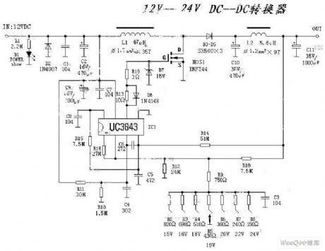
Different types of voltage value such as 15V, 16V, 18V, 20V, 22V, and 24V etc. can be changed by changing the resistance.
L1 uses a magnetic loop of 2cm and 1.7 polyester varnished wires to wind it closely for 35 turns. And then it is sealed up by silicon rubber, otherwise it is easy to generate sizzling sound.
Meanwhile the direction of the route should be paid attention to, otherwise the sizzling sound will also occurand the field-effect tube emits heat and destroys due to the self-excitation caused by routing problem. If possible, paster component of UC3843 can also be used.
L2 can use the magnetic loop of old energy-saving light to wind closely. There is no special requirement.
(View)
View full Circuit Diagram | Comments | Reading(7334)
The regulator: DC-DC circuit, power supply monitor pin and its main features LM199AH-20/299AH-20/399AH-50
Published:2011/9/10 18:58:00 Author:Seven | Keyword: DC-DC circuit, power supply, monitor pin
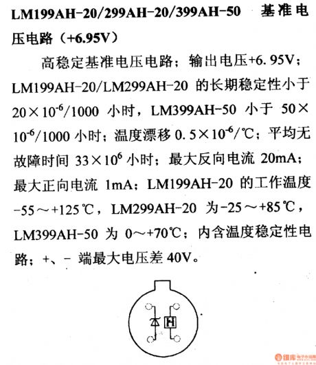
LM199AH-20/299AH-20/399AH-50 reference voltage circuit (+6.95V) This is a highly stable reference voltage circuit; its output voltage is 6.95v; the long-term stability of LM199AH-20/299AH-20 is lower than 20*10-6/1000h, LM399AH-50 is less than 50*10-6h; temperature drifting is 0.5*10-6/℃; the average non-fault time is 33*10-6h; the maximum backward current is 20mA; the maximum forward current is1mA; LM199AH-20 working temperature is -55~+125℃, LM299AH-20 working temperature is -25~+85℃, LM399AH-50 working temperature is0~+70℃; it contains the temperature stability circuit; the maximum voltage gap between the positive pole and the negative pole is 40V.
(View)
View full Circuit Diagram | Comments | Reading(799)
Same Frequency Detection Circuit of Low Frequency and Small Drift Polarity Converting Type
Published:2011/8/25 22:48:00 Author:Michel | Keyword: Same Frequency, Detection Circuit
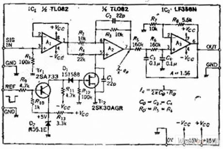

Circuit's Functions
The synchronous detection circuit with reverse phase or same phase whose work frquency is lower than dozens of HZand theycan be adpoted in the whole low frequency band.The circuit's analog switch uses the general N channel J-an FET. Smooth circuit adds12DB/OCT low-pass filter,which shortens the response time.It is easy to eliminate higher harmonic because the detection uses total wave rectifier system.This circuit is widely used in the lock-in amplifier detection circuit of measuring tiny voltage.
Circuit's Work Principle
OP amplifier A1 is impedance buffer ,A1 can be removed if the former stage's output impedance is as low as OP amplifier. (View)
View full Circuit Diagram | Comments | Reading(1126)
Battery Quick Charger Circuit of Digital Potentiometer XC9104
Published:2011/8/25 22:45:00 Author:Michel | Keyword: Digital Potentiometer, Battery Quick Charger Circuit
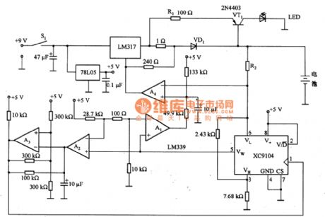
The above picture is battery quick charger circuit of digital potentiometer XC9104.When the power switch S1 switches on, 9 V voltage begins to charge the battery via LM317.When S1 switches on,Vw end voltage of XC9104 rises automatically,thus sliding port Vw is linked to VL end.In this state, A1 outputs high level, LM317 charges batteries quickly.The battery charges and the voltage gradually rises and XC9104 Vw end voltage rises automatically.A3 harmonic oscillator amplitude increases periodically according to the proportion that XC9104 remains. (View)
View full Circuit Diagram | Comments | Reading(2606)
0~2OV/1A Stable Precision Power Supply Circuit of LM199
Published:2011/9/8 1:20:00 Author:Michel | Keyword: Stable Precision , Power Supply Circuit
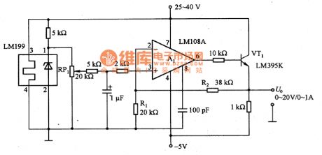
The picture is 0~2OV/1A stable precision power supply circuit of LM199.LM199is a drift integrated voltage modulewith a long-term stability and very small temperature . The circuit uses its output voltage source as the benchmark voltage power supply and that is 0 ~ 20 V adjustable stable power supply. RP1 uses 20 laps line potentiometer to change its resistance value,which can make the output voltage adjust between 0~20V.
VT1 transistor (LM395K) is used as the output circuit series control device.It is 5μA input base current and there are power transistor with overcurrent limiting and overheating protection functions.LM395K usually works in safety work range thus there is no necessary for external circuit to connect with overcurrent protection circuit,which makes the circuit very simple.In the circuit,RP1 needs to choose resistor with good temperature properties and R1 and R2need to choose metal film resistance with good temperature properties. (View)
View full Circuit Diagram | Comments | Reading(2146)
The small power mini switch regulated power supply circuit formed by WS157 and WS106
Published:2011/9/3 2:53:00 Author:leo | Keyword: Small power, mini, switch regulated power supply
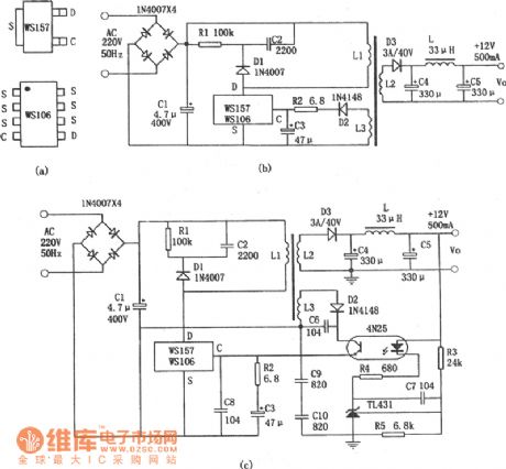
The picture shows a small power mini switch regulated power supply made by WS157 and WS106. WS157 and WS106 are a type of control component in regulated power supply. This kind of component integrates control circuit and power switch on the same chip which has the PWM controlling function and over current and over heat test function. It needs suitable switch transformer and some components to keep steady work situation. The regulate power supply made by it can directly convert the DV 220 V to low DC voltage. And the power of WS157 is 18 W while the power of WS106 is 12 W. (View)
View full Circuit Diagram | Comments | Reading(1841)
Circuit diagram of small-size battery charger available to choosing charging time
Published:2011/9/9 8:01:00 Author:Vicky | Keyword: small-size battery charger , choosing charging time
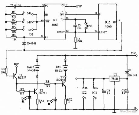
Small-size battery charging circuit which can choose charging time is shown in the above picture. The charger has the required constant current source digital circuit timer for charging safely. It can be used to charge 12 pieces of nickel-cadmium batteries. There are three grades of charging time for choice, and they are 5 hours, 14 hours, and 24 hours. The voltage adaptor of 15V outputs voltage supply the power for the circuit. 15V DC voltage is sent to the two constant current sources to charge the battery. In addition, IC3 (7810) provides the stable 10V power voltage for the timer。 (View)
View full Circuit Diagram | Comments | Reading(1743)
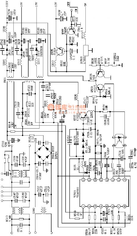
the absolutely useful switch power supply:the Kaige 4C7108 power supply(A4)
Published:2011/8/20 2:22:00 Author: | Keyword: absolutely useful , switch power supply
View full Circuit Diagram | Comments | Reading(1023)
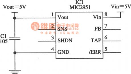
5V Current Limiter Composed Of MIC2951 Circuit
Published:2011/9/6 4:48:00 Author:Felicity | Keyword: 5V, Current Limiter
View full Circuit Diagram | Comments | Reading(938)
A High Power Drive Circuit without an Exterior Switch
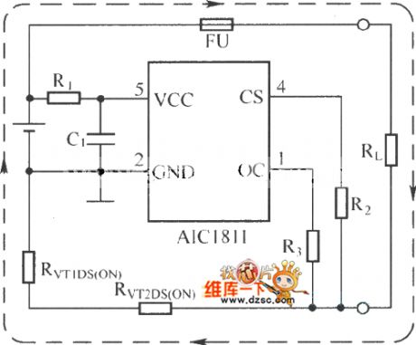
Published:2011/9/3 10:00:00 Author:Zoey | Keyword: High Power Drive, LED Circuit, Exterior Switch
High power LED, candescence light bulb and fluorescence lamp are widely used for illumination. Current source is the best way to offer LED power. As to the LEDs that have a current larger than 0.35A, induction switched voltage regulator is the best matcher.
This design solution offers a series of circuits for single power integrated circuit regulators, so as to improve efficiency and reduce the size.
Circuit in picture 1,2 and 3 adopt circuit that is composed of three or four alkalescence cells, NiMH cells or NiCd cells for power supply. Circuits in picture 4 and 5 can be used in automobiles, industry systems and emergency branch systems and telecoms, the circuits’ circuitry voltage of switch system is 12V, 24V or 42V.
When the circuits begin to work, they will darkle. Resistances and potentiometers can get power by VD or CVL terminal of the interior voltage regulator.
(View)
View full Circuit Diagram | Comments | Reading(896)
A Circuit Diagram of Discrete Elements of the Touch Switch
Published:2011/9/3 20:08:00 Author:Zoey | Keyword: Circuit Diagram, Discrete Elements, Touch Switch
The circuit of discrete elements of the touch switch has been shown in picture below. This circuit is composed of an induction magnifier, a memorizer and an AC driver. As soon as a finger touches the insulted plate, a small AC signal will be added to the gate of Tr1, the signal will produce square wave on R4 after being magnified, and then it will charge to C3 through Tr3, after that it will produce direct input voltage on R8, the voltage will be added to single crystal transistor Tr6. Finally, Tr6 will give rise to remittent oscillation and trigger the controllable silicon. The longer the switch is touched, the larger of voltage on R8 will be. As soon as the finger leaves the switch, load will be cut off. (View)
View full Circuit Diagram | Comments | Reading(1164)
The practical nickel cadmium battery automatic charger circuit
Published:2011/9/4 20:40:00 Author:TaoXi | Keyword: Practical nickel cadmium battery, automatic charger

The charge which is introduced in this article can supply the stable charging current and it has the timing circuit to control the charging time.
As the figure 4-17 shows, when youpress the button SW1, the city electricity is connected, the relay RL1 closes, the red light emitting diode LED2 turns on, this means that the charger has connected with the power. The regulator IC5 supplies the 12V DC voltage to the RL1. The regulator IC2 supplies the +5V voltage to the logic circuit. The constant current source is composed of IC1, it can output the stable charging current. R1 fixes the charging current at 50mA (used to charge the LR06 type storage battery), R6 fixes the charging current at 11mA (used to charge the 9V 6F22 type laminated battery).
(View)
View full Circuit Diagram | Comments | Reading(949)
Large power adjustable charger circuit
Published:2011/9/4 20:41:00 Author:TaoXi | Keyword: Large power, adjustable, charger, circuit

The principle of this charging device is as shown in figure 3-7, the maximum output current is 20A, the highest charging voltage is 80V. It can be adjusted from 0V, so it can charge all kinds of batteries and the battery groups or battery groups in series which have the same specifications, such as five 12V batteries in series. By charging the series batteries, we can shorten the length of wiring and reduce the power consumption, so the operating efficiency is improved.
(View)
View full Circuit Diagram | Comments | Reading(984)
Two On-off Circuits controlled by CMOS System Direct Motor
Published:2011/9/3 10:22:00 Author:Zoey | Keyword: On-off Circuits, CMOS System, Direct Current, Motor

Circuit (a) is controlled by 24-V and 18-A direct current motor CMOS. NPN reset tube 2N282 needs to get 20A current, and Q1 150mA. Circuit (b) is controlled by CMOS direct current motor that can input high level, the Darlington uses a PNP 2N6285,collector power of the incentive transistor Q1 is not connected to CMOS power, instead, it should be connected to the TV power. (View)
View full Circuit Diagram | Comments | Reading(1310)
The regulator: DC-DC circuit, power supply monitor pin and main features LM2940
Published:2011/8/30 2:23:00 Author:Seven | Keyword: DC-DC circuit, power supply, monitor pin
LM2940 serial low voltage gap 3-terminal stabilizer (forward output) This is a low voltage gap 5-terminal stabilizer whose output voltage is stable; its output voltages are 5V, 8V and 10V; output current is 1A; output current is 1A; minimum input-output voltage gap is low than 0.8V; maximum input voltage is 26V; working temperature is -40~+125℃; it contains the static current step-down circuit, current protection, over-heat protection, battery inversed grafting and inversed inverting protection circuit. The approaching type is W2940.
(View)
View full Circuit Diagram | Comments | Reading(754)
The regulator: DC-DC circuit, power supply monitor pin and its main features LM330
Published:2011/8/30 2:23:00 Author:Seven | Keyword: DC-DC circuit, power supply, monitor pin
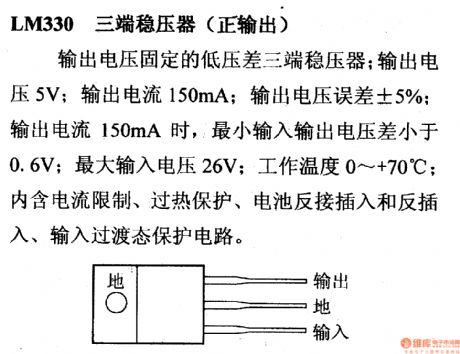
LM330--3-terminal stabilizer(positive output) This is a 3-terminal stabilizer with fixed output voltage; the output voltage is 5V; output current is 150mA; output voltage fault is ±5%; when the output current is 150mA, the minimum input-output voltage is lower than 0.6V; the max input voltage is 26V; the working temperature is 0~+70 ℃; it contains the current limitation, overheat protection, batter reverse connection inserting and inverting inserting and input transition state protection circuit.
(View)
View full Circuit Diagram | Comments | Reading(812)
The regulator: DC-DC circuit, power supply monitor pin and its main features LM342
Published:2011/8/30 2:23:00 Author:Seven | Keyword: DC-DC circuit, power supply, monitor pin
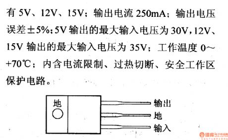
The 3-terminal regulator (forward output) of LM342 series This is a 3-terminal regulator of fixed output voltage; its output voltages are 5V, 12V and 15V; its output current is 250mA; its output voltage difference is ±5%; when the output voltage is 5V, the max input voltages are 30V; when it is 12V or 15V, the max input voltage is 35V; its working temperature is 0~+70℃; it contains the current limitation, over-heat break-down and secure working area protection circuit.
(View)
View full Circuit Diagram | Comments | Reading(932)
| Pages:59/291 At 204142434445464748495051525354555657585960Under 20 |
Circuit Categories
power supply circuit
Amplifier Circuit
Basic Circuit
LED and Light Circuit
Sensor Circuit
Signal Processing
Electrical Equipment Circuit
Control Circuit
Remote Control Circuit
A/D-D/A Converter Circuit
Audio Circuit
Measuring and Test Circuit
Communication Circuit
Computer-Related Circuit
555 Circuit
Automotive Circuit
Repairing Circuit