
power supply circuit
Index 55
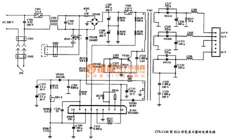
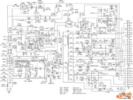
The power supply circuit diagram of CTX-C146 EGA color display
Published:2011/11/1 20:56:00 Author:Ecco | Keyword: power supply , EGA , color display
View full Circuit Diagram | Comments | Reading(1261)
Using LM386 as low-power positive and negative regulated power supply circuit diagram
Published:2011/10/20 20:42:00 Author:Rebekka | Keyword: low-power, positive , negative , regulated power supply

View full Circuit Diagram | Comments | Reading(1253)
Charging circuit composed of μA741
Published:2011/10/20 22:38:00 Author:Rebekka | Keyword: Charging circuit
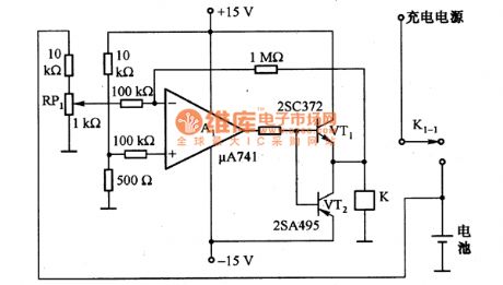
The figure shows the charging circuit composed of μA741. The battery voltage passes RP1 and adds to the inverting input terminal of A1. When the battery voltage is low, A1 outputs high, VT1 and VT2 turn on, the relay K will be energized, then the contacts K1-1 close. The charging power supply charges for the battery. When the battery is fully charged, the voltage is increased, A1 outputs low level, VT1 and VT2 stop, the relay K loses power,then the K1-1 disconnects, the battery will stops charging. (View)
View full Circuit Diagram | Comments | Reading(1674)
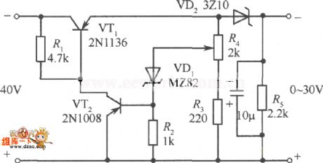
Output 15OV/100mA regulator circuit diagram
Published:2011/10/20 22:34:00 Author:Rebekka | Keyword: regulator circuit
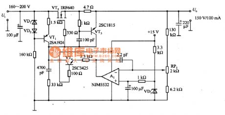
The figure shows the output 150V/100mA regulator circuit. VT3 is the over-current protection circuit, when the output is in short circuit, VT3 protection circuit starts to work. The current in VT2 is controlled at 12OmA. At this time, it adds all the input voltage to the VT2 input voltage drain - source, the production loss is about 2OW. (View)
View full Circuit Diagram | Comments | Reading(1626)
AC switch circuit diagram using optical controlling
Published:2011/10/18 3:31:00 Author:Rebekka | Keyword: optical control , AC switch
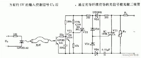
When it has 5V input control signal UE,optical signals pass optical fiber transmission. (View)
View full Circuit Diagram | Comments | Reading(1576)
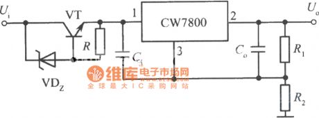
High input-high output integrated regulated power supply circuit circuit diagram 4
Published:2011/8/19 2:29:00 Author:Jessie | Keyword: High input-high output , integrated regulated power supply
View full Circuit Diagram | Comments | Reading(787)
Lithium battery charger circuit diagram
Published:2011/10/17 1:29:00 Author:Ecco | Keyword: Lithium battery charger
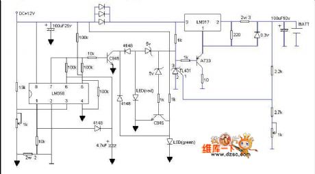
In this circuit, when it is in charging status, red light flashing shows that it is charging, and the green light flashing shows it is going to be full, then green light is lit completely, then it is full. As long as you have a 12V power supply, after finishing the circuit, you do not install the battery firstly, and adjusting the adjustable resistor in right corner make the battery output be 4.2V, then transferred adjustable resistor in the left corner make the pin 3 of LM358 be 0.16V, then the charging current is 380mA, and the circuit is ultra-fast, and three diodes connected in parallel is used to prevent overheating of LM317, and LM317 must add heat sink. The transistor shown in the figure can choose any model.
(View)
View full Circuit Diagram | Comments | Reading(3346)
The circuit of mobile phone charger
Published:2011/9/26 1:12:00 Author:Rebekka | Keyword: Mobile phone charger
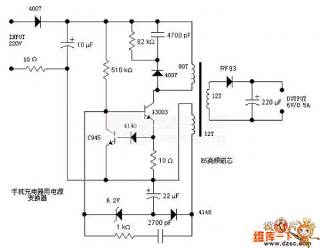
Here is the schematic diagram of the mobile phone charger circuit:
(View)
View full Circuit Diagram | Comments | Reading(7520)
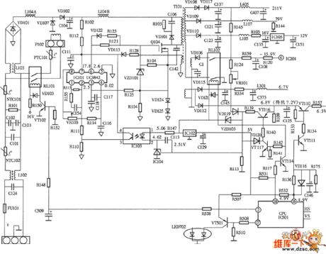
Galaxy yh-250 v2.1 3.3v power supply circuit diagram
Published:2011/9/15 21:43:00 Author:Rebekka | Keyword: Galaxy , 3.3v power supply
It uses FETs q13, tl43l and the comparator Lm339 to form regulated voltage circuit. It is shown as the figure. The sawtooth signal of IC ka7500b's first pin ⑤ is sent by 10kω resistor to the comparator lm393's pins ②, ⑥ (lm393 is composed of the two comparators, in the circuit, the two comparators are connected in parallel as a comparator, that is the same-phase terminals ③ and ⑤ are connected, and inverting terminals ⑥ and ② are connected, and the output terminals ⑦ and ① are connected), and the pulse width output by pins ①, ⑦ of lm393 is decided by the potential of lm393's pins ③, ⑤.
(View)
View full Circuit Diagram | Comments | Reading(1982)
LG PT-48A82 Rear projection TV power supply circuit diagram
Published:2011/9/15 1:56:00 Author:Rebekka | Keyword: Rear Projection TV
View full Circuit Diagram | Comments | Reading(8250)
MAG Long 796FDⅡtype color display switching power supply (UC3842) circuit diagram
Published:2011/9/15 1:57:00 Author:Rebekka | Keyword: MAG Long , color display switching
View full Circuit Diagram | Comments | Reading(4518)
Photocoupler high voltage regulator circuit diagram
Published:2011/9/26 1:34:00 Author:Rebekka | Keyword: photocoupler, high voltage regulator
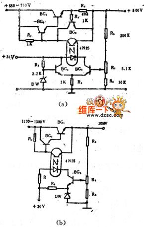
It is the series regulator circuit, and the amplifier tubes need to use relatively high-voltage transistor, if it uses the good insulation characteristics of optical coupler between input and output, it will realize high-pressure control. In the (a) and (b) figures, they are the high-voltage regulator circuit with using optocoupler. In Figure (a), when the output voltage rises for some reason, the BG5 bias increases, light-emitting diode's forward current increases, so that the phototransistor collector junction voltage decreases. (View)
View full Circuit Diagram | Comments | Reading(2392)
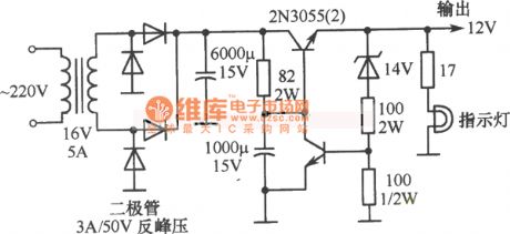
12V simple regulator circuit diagram 3
Published:2011/9/26 21:17:00 Author:Rebekka | Keyword: simple regulator
View full Circuit Diagram | Comments | Reading(1399)
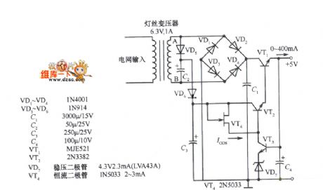
Storage and Ni-MH Batteries Automatic Charger Circuit Diagram
Published:2011/9/14 22:43:00 Author:Rebekka | Keyword: Storage , Ni-MH Batteries , Automatic Charger
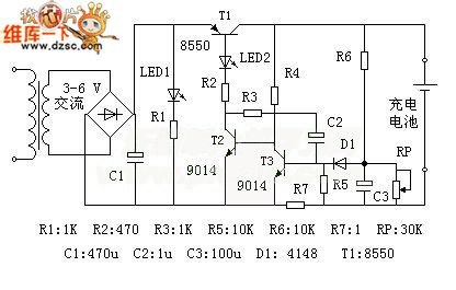
Batteries, Ni-MH battery automatic battery charger circuit, nickel hydrogen batteries, rechargeable battery are widely used in daily life, but often because of improper charge, the battery dies prematurely.
Properties: 1. The charger has a pulse current limiting charge, trickle charge and other functions in order to achieve intelligent charge without human care.2. The charger is triggered by battery power. There is no voltage output without connecting the battery; only the battery is connected correctly, the charge current will output. It has short circuit protection or reverse protection.3. The circuit has awide application. It performs in: ⑴ Wide input voltage range; ⑵ As long as you adjust the potentiometer, it will be suitable for other types of rechargeable batteries. (View)
View full Circuit Diagram | Comments | Reading(5104)
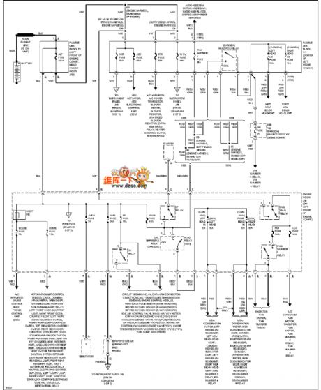
Toyota power supply circuit
Published:2011/9/26 1:04:00 Author:Ecco | Keyword: Toyota power supply
View full Circuit Diagram | Comments | Reading(1117)
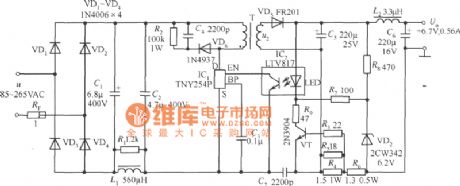
+6.7 V, 0.56A Constant current cell phone battery charger circuit composed of TNY254P
Published:2011/9/25 22:07:00 Author:Ecco | Keyword: +6.7 V, 0.56A , Constant current , cell phone , battery charger
View full Circuit Diagram | Comments | Reading(2367)
Single-supply transforming into positive and negative dual power supply circuit
Published:2011/9/13 1:15:00 Author:Rebekka | Keyword: Single-supply transforming , positive and negative , dual power supply
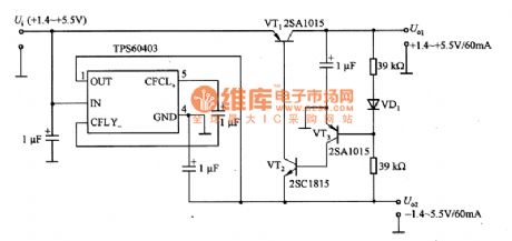
In the circuit, VD1 is used to compensate the UBE temperature characteristics of VT3. TPS60403 integrated chip can change the input voltage +1.4 ~ +5.5 V into a negative voltage. And output positive and negative voltageare established at the same time. The circuit is used for battery-powered electronic devices. (View)
View full Circuit Diagram | Comments | Reading(2073)
Motorcycle charging circuit diagram
Published:2011/9/14 22:16:00 Author:Rebekka | Keyword: Motorcycle charging
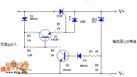
The circuit uses ACpositive half cycle charge. Charging speed is fast and it can extend battery life. People use the charger on ordinary motorcycle. It has an excellent performance and saves 5% fuel. It is a practical charging circuit. Working principle: (shown as the figure)AC voltage is also added to the D1 and SCR. It passes the half-wave rectifier D1 to R1、R2、Q1、R3 and provides trigger voltage to SCR. SCR is charging to the battery at this time. When the battery voltage isup to 13.5V, the ZD1 will be conducted. The voltage passing R5、D2 provides bias to Q2, thenQ2 will be conducted. Q1 reverse bias will be closed. SCR stops outputting when battery voltage is lower than 13-13.5V.
(View)
View full Circuit Diagram | Comments | Reading(6267)
100w VMOS tube inverter power supply circuit
Published:2011/9/18 21:11:00 Author:Ecco | Keyword: 100w , VMOS tube, inverter power supply

As shown in Figure 4-11, the circuit is composed of 555 trigger and step-down rectifier circuit. When the hands touch metal A, the sensor signals make the internal comparator 555 turn and set, K pulls, the contact K1-1 closes; if people touch A again, K releases.
(View)
View full Circuit Diagram | Comments | Reading(1738)
5V fixed voltage power supply circuit diagram with doubler rectifier
Published:2011/8/22 22:31:00 Author:Rebekka | Keyword: doubler rectifier , 5V , fixed voltage , power supply
View full Circuit Diagram | Comments | Reading(1337)
| Pages:55/291 At 204142434445464748495051525354555657585960Under 20 |
Circuit Categories
power supply circuit
Amplifier Circuit
Basic Circuit
LED and Light Circuit
Sensor Circuit
Signal Processing
Electrical Equipment Circuit
Control Circuit
Remote Control Circuit
A/D-D/A Converter Circuit
Audio Circuit
Measuring and Test Circuit
Communication Circuit
Computer-Related Circuit
555 Circuit
Automotive Circuit
Repairing Circuit