
Signal Processing
Index 127
Low_distortion_oscillator
Published:2009/7/24 9:01:00 Author:Jessie
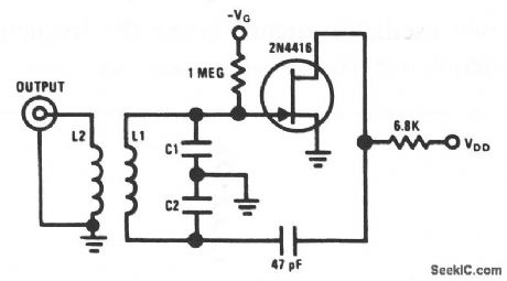
The 2N4416 JFET is capable of oscillating in a circuit, where harmonic distortion is very low. The JFET oscillator is excellent when a low harmonic content is required for a good mixer circuit. The values given are for a 20-MHz oscillator. National Semiconductor, Linear Applications Handbook, 1991, p. 114. (View)
View full Circuit Diagram | Comments | Reading(1)
Stable_low_frequency_crystal_oscillator
Published:2009/7/24 9:00:00 Author:Jessie
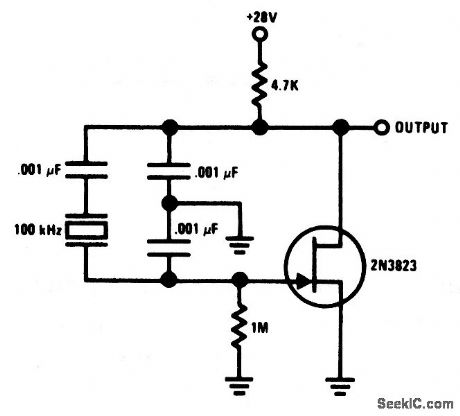
This Colpitts crystal oscillator is ideal for low-frequency oscillator applications. Excellent stability is assured because the 2N3823 JFET circuit loading does not vary with temperature. National Semiconductor, Linear Applications Handbook, 1991, p. 114. (View)
View full Circuit Diagram | Comments | Reading(1158)
JFET_Pierce_crystal_oscillator
Published:2009/7/24 8:59:00 Author:Jessie
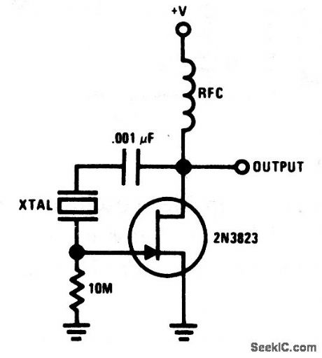
This circuit allows a wide frequency range of crystals to be used without circuit modification. Because the JFET gate does not load the crystal, good Q is maintained, which thus ensures good frequency stability. National Semiconductor, Linear Applications Handbook, 1991, p. 106. (View)
View full Circuit Diagram | Comments | Reading(919)
Temperature_compensated_crystal_oscillator
Published:2009/7/24 8:27:00 Author:Jessie
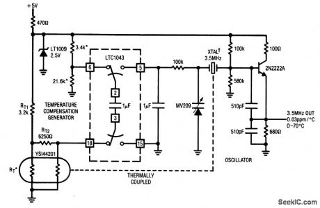
This circuit uses an LTC1043 to differentiate between a temperature-sensing network and a dc reference. The singla-ended output biases a varactortuned crystal oscillator to compensate drift. The varactor-crystal network has high dc impedance, with eliminates the need for an output amplifier from the LTC1043. Connect other LTC1043 pins as follows: 4 to +5 V, 16 to ground through a 0.001-μF capacitor, and 17 directly to ground. Linear Technology, Linear Applications Handbook, 1990, p. AN3-15. (View)
View full Circuit Diagram | Comments | Reading(2249)
Crystal_oscillator_clock_circuits_for_digital_systems
Published:2009/7/24 8:58:00 Author:Jessie
These two oscillator circuits cover the frequency range for most digital-system clock requirements. Linear Technology, Linear Applications Handbook, 1990, p. AN31-11. (View)
View full Circuit Diagram | Comments | Reading(713)
High_frequency_sine_wave_generator_with_quadrature_output
Published:2009/7/24 8:57:00 Author:Jessie
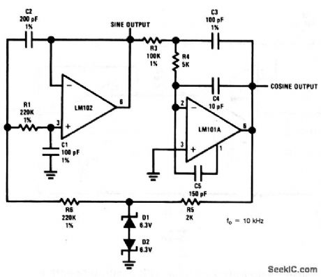
This circuit uses an LM102 and an LM101A to provide both a sine and cosine output at 10 kHz. National Semiconductor, Linear Applications Handbook, 1991, p. 84. (View)
View full Circuit Diagram | Comments | Reading(904)
Low_frequency_sine_wave_generator_with_quadrature_output_1
Published:2009/7/24 8:28:00 Author:Jessie
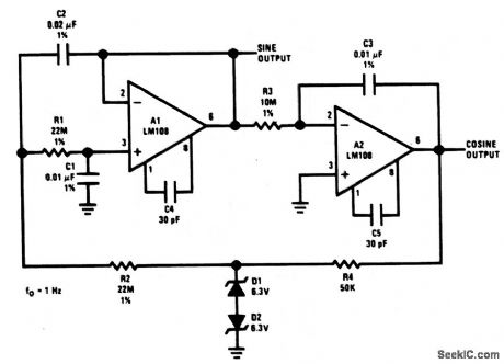
This circuit uses two LM108s to provide a both a sine and cosine output at 1 Hz. National Semiconductor, Linear Applications Handbook, 1991, p. 84. (View)
View full Circuit Diagram | Comments | Reading(938)
Wien_bridge_sine_wave_oscillator
Published:2009/7/24 8:25:00 Author:Jessie
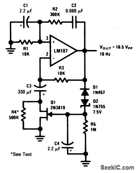
This circuit differs from other Wien-bridge oscillators described in this chapter only in the form of negative-feedback stabilization. Negative peaks in excess of -8.5 V cause D1 and D2 to conduct, which charges C4. The C4 charge biases Q1, which determines amplifier gain. C3 provides low-frequency roll-off in the feedback network, and prevents offset voltage/current errors from being multiplied. R5 is chosen to adjust the negative feedback loop so that Q1 is operated at a small negative gate bias. National Semiconductors, Linear Applications Handbook, 1991, p. 28. (View)
View full Circuit Diagram | Comments | Reading(2294)
Stable_RC_oscillator
Published:2009/7/24 8:12:00 Author:Jessie


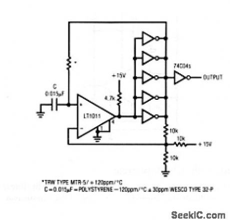

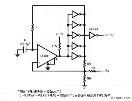
This circuit shows an RC clock circuit, which depends primarily on the RC elements for stability. The nominal-120-ppm/℃ temperature coefficient of the polystyrene capacitor is offset by the opposing positive temperature coefficient of the specified resistor. Linear Technology Corporation, Linear Appications Handbook, 1990, p. AN12-7. (View)
View full Circuit Diagram | Comments | Reading(837)
Reset_stabilized_oscillator
Published:2009/7/24 8:10:00 Author:Jessie
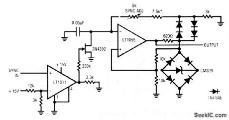
This circuit shows a synchronous clock generator, where the output locks at a higher frequency than the sync input. The maximum practical output-frequency to sync-frequency ratio is about 50 times. The output frequency is set to a multiple of the input frequency by the 5-kΩ Sync Adj pot. Linear Technology Corporation, Linear Applications Handbook, 1990, p. AN12-6. (View)
View full Circuit Diagram | Comments | Reading(644)
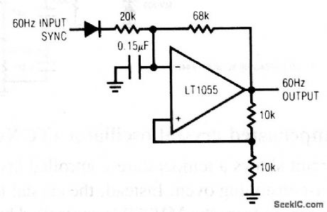
Synchronized_oscillator
Published:2009/7/24 8:08:00 Author:Jessie
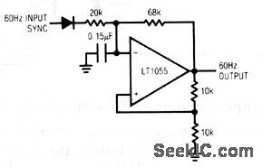
This circuit shows a line-synchronized oscillator that will not lose lock under noisy line conditions. The circuit is suited to applications that require a reliable 60-Hz line-synchronous clock, and is superior to the usual zero-crossing detectors and simple voltage-level detectors. In this circuit, the basic RC multivibrator is tuned to free-run near 60 Hz, but the line-derived sync input forces the oscillator to lock on the ac line. Linear Technology Corporaton, Linear Applications Handbook, 1990, p. AN12-6. (View)
View full Circuit Diagram | Comments | Reading(1390)
Voltage_controlled_crystal_oscillator_VCXO
Published:2009/7/24 8:07:00 Author:Jessie
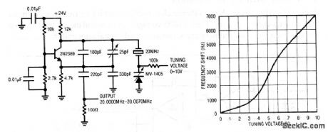
This circuit shows a voltage-controlled crystal oscillator. Figure 5-33B shows the tuning characteristics (frequency shift versus tuning voltage). Linear Technology Corporation, Linear Appications Handbook, 1990, p. AN12-5. (View)
View full Circuit Diagram | Comments | Reading(1675)
Quartz_stabilized_bridge_oscillator
Published:2009/7/24 5:33:00 Author:Jessie
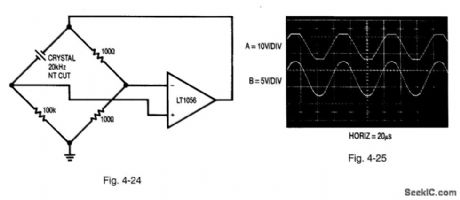
Figure 4-24 shows a bridge-based oscillator, where one leg of the bridge is replaced with a resonant element. Figure 4-25 shows the waveforms. With the crystal removed, the circuit is a basic non-inverting gain-of-two amplifier with grounded input. Inserting the crystal closes a positive-feedback path at the crystal resonant frequency. The amplifier output (trace A, Fig. 4-25) swings in an attempt to maintain input balance. Excessive circuit gain prevents linear operation, and oscillations start when the amplifier repeatedly overshoots in an attempt to null the bridge. The high Q of the crystal is evident in the filtered waveform (trace B) at the amplifier positive input. LINEAR TECHNOLOGY APPLICATION NOTE 43, P. 27. (View)
View full Circuit Diagram | Comments | Reading(682)
Bridge_oscillator_with_square_wave_output
Published:2009/7/24 5:33:00 Author:Jessie
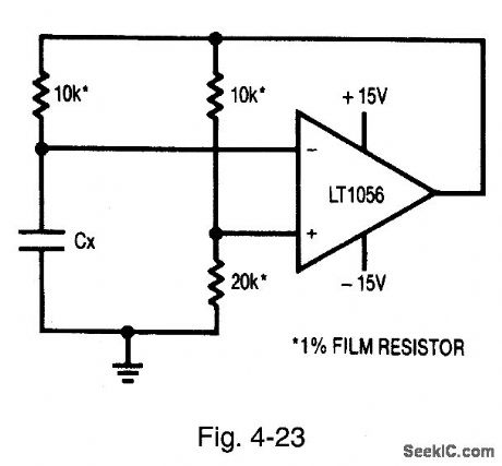
Figure 4-23 shows an oscillator circuit formed from the circuit of Fig. 4-22. In effect, the Fig. 4-23 circuit is a classic op-amp multivibrator (MV). The 10-kΩ/20-kΩ bridge leg provide switching-point hysteresis, with Cx charged through the remaining 10-kO resistor. When Cx reaches the switching point, the amplifier output changes state, abruptly reversing the sign of the positive output. The charging direction of Cx, also reverses to sustain oscillation. Output frequency depends on bridge components (at frequencies that are low compared to amplifier delays). Amplifier input errors tend to cancel, and supply shifts are generally rejected. The duty cycle is influenced by output saturation and supply asymmetry. LINEAR TECHNOLOGY, APPLICATION NOTE 43, P. 27. (View)
View full Circuit Diagram | Comments | Reading(744)
Quartz_stabilized_bridge_oscillator_with_sine_wave_output
Published:2009/7/24 5:35:00 Author:Jessie

Figure-26 shows a crystal-controlled bridge-based oscillator, where one leg of the bridge is formed by a lamp(a classic circuit).Figure 4-27 shows the waveforms,As the oscillation amplitude builds, the lamp current increases, as does lamp resistance. This causes a reduction in gain, and the circuit finds a stable operating point, The 15-pF capacitor suppresses Spurious oscillation. The amplifier output(trace A, Fig,4-27)is a sine wave without about 1.5%distortion(trace B),caused primarily by common-mode swing,LINEAR TECHNOLOGY,APPLICATION NOTE 43,P. 28. (View)
View full Circuit Diagram | Comments | Reading(699)
Temperature__compensated_crystal_oscillator_TCXO
Published:2009/7/24 8:01:00 Author:Jessie
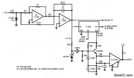
This circuit shows a temperature-controlled crystal oscillator without an expensive, power-consuming oven. Instead, the crystal frequency is controlled by an MV-209 varactor. In turn, the MV209 is controlled by a linear thermistor in the feedback loop of A1. Linear Technology Corporaton. Linear Appications Handbook, 1990, p. AN12-4. (View)
View full Circuit Diagram | Comments | Reading(1135)
Oven_controlled_crystal_oscillator
Published:2009/7/24 7:56:00 Author:Jessie
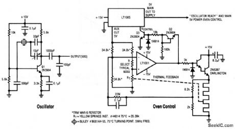
This circuit shows a Pierce-class oscillator with fine-frequency trimmer and an oven-control system. The LT1005 voltage regulator and the LT1001 op amp are used in a precision temperature-servo to control crystal temperature. Linear Technology Corporation, Linear Applications Handbook, 1990, p. AN12-3. (View)
View full Circuit Diagram | Comments | Reading(2346)
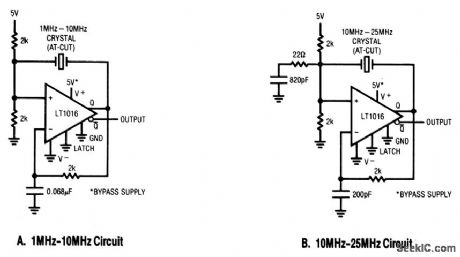
Crystal_oscillator_10_to_25_MHz
Published:2009/7/24 7:52:00 Author:Jessie
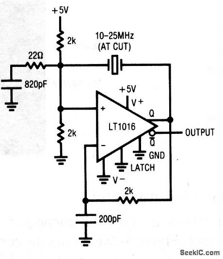
This circuit shows an LT1016 connected as an oscillator, which is suitable for operation in the 10- to 25-MHz range. Notice that the damper network (C=820 pF, R=22) prevents the AT-cut crystal from operating in the overtone mode. Linear Technology Corporation, Linear Applications Handbook, 1990, p. AN12-3. (View)
View full Circuit Diagram | Comments | Reading(775)
Crystal_oscillator_1_to_10_MHz
Published:2009/7/24 7:50:00 Author:Jessie
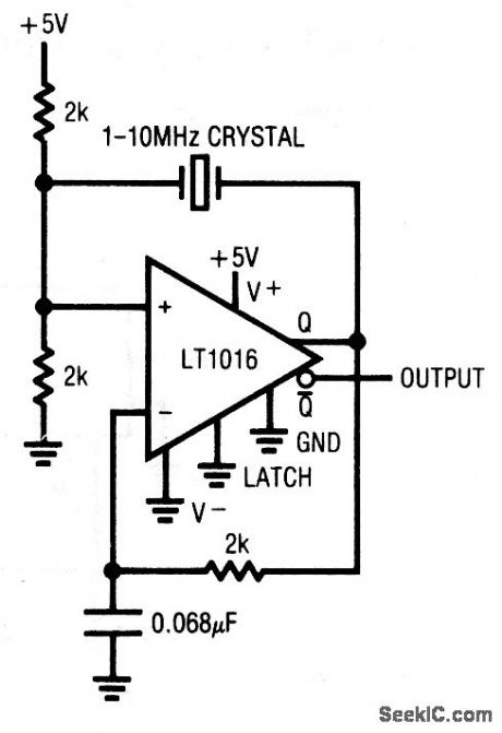
This circuit shows an LT1016, which is connected as an oscillator suitable for operation in the 1- to 10-MHz range. Linear Technology Corporaton, Linear Applications Handbook, 1990, p. AN12-3. (View)
View full Circuit Diagram | Comments | Reading(658)
Micropower_oscillator_with_fixed_frequency_and_variable_duty_cycle_
Published:2009/7/24 7:13:00 Author:Jessie
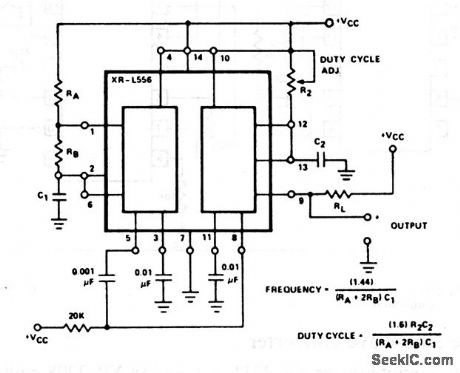
In this circuit, timer 1 is operated in the astable mode, and timer 2 is operated monostable; timer 1 triggers timer 2. The output (pin 9) has the same frequency as timer 1, but with a duty cycle determined by the timing cycle of timer 2. The output duty cycle can be adjusted from 1 to 99% by R2, typically a 10-kΩ potentiometer. EXAR Corporation Databook, 1990, p. 5-222. (View)
View full Circuit Diagram | Comments | Reading(839)
| Pages:127/195 At 20121122123124125126127128129130131132133134135136137138139140Under 20 |
Circuit Categories
power supply circuit
Amplifier Circuit
Basic Circuit
LED and Light Circuit
Sensor Circuit
Signal Processing
Electrical Equipment Circuit
Control Circuit
Remote Control Circuit
A/D-D/A Converter Circuit
Audio Circuit
Measuring and Test Circuit
Communication Circuit
Computer-Related Circuit
555 Circuit
Automotive Circuit
Repairing Circuit