
Signal Processing
Index 25
wee willy Receiver
Published:2012/12/6 19:48:00 Author:muriel | Keyword: wee willy Receiver
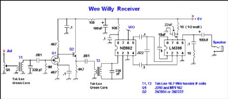
The receiver is a direct conversion type with a manual RF gain control in the form of a 5K potentiometer. Listening to a weak signal on the desired frequency the RF stage and the mixer core ( T1 and T2 ) adjustments are made until you hear the loudest possible signal, keeping the input test signal as low as possible. When the receiver is connected to a doublet antenna there is no lack of incoming signal, which can be controlled by the front panel RF gain control.
The antenna and 6 volt supply is switched manually from TX to RX mode and back by a front panel mounted switch. If you can not find Tak Lee green 10.7 MHz IF coils, probably any other brand of 10.7 MHz slug tuned IF transformer would work. The Mouser catalog number 421F123 would work well and in another 80 meter project I used it with a 470 pF capacitor instead of the 330 pF cap shown. I would start with Dick's 330 pf cap and if it will not tune to resonance sharply, slightly increase the cap value up to see if a bit more capacity is required to resonate it on the desired 75 Meter frequency. Note that the secondary coil on the L1 transformer in the transmitter schematic is unused. If your 10.7 MHz IF coil has a built in capacitor at the base, remove it.
During receive, the standby drain current at 6.0 volts was 24 mA and on loud signals it rose to 100 mA. If this is too much, probably the easiest thing to do would be to put in a series resistor from positive to the LM386 to limit the drain current. To get output on the speaker it is a matter of how loud you want it for the drain you draw. If earphone only reception is okay, then the drain could be reduced considerably. (View)
View full Circuit Diagram | Comments | Reading(4844)
wee willy transmitter
Published:2012/12/6 19:47:00 Author:muriel | Keyword: wee willy transmitter
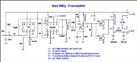
This transmitter uses an electret condenser microphone ( Dick used an Archer 270-90 ). The mic is built right into the front panel of the chassis and this of course guarantees short mic leads. A 741 op amp is used as a speech amplifier which in turn drives the balanced modulator a Signetics NE602 doubly balanced mixer. The input and output impedance of the NE602 mixer is around 1500 ohms.
To adjust the transmitter, set the bias control on the VN10 stage to ground and tweak L1 to resonance using an RF probe or scope on the VN10 input. The input signal must be audio, spoken into the front panel microphone to get the DSB. Once L1 is tuned, connect a 50 ohm load to the antenna with some sort of RF indicator (such as a RF power meter) and advance the bias control to give a watt or so output. Then speaking into the microphone should result in a DSB signal suitable for communicating on QRP! No audio input should result in no RF output. The supplied voltage should be kept at 6 volts, remembering that NE602's cannot stand voltage greater than 9 volts. With suitable voltage control such as a 6.8 volt zener diode on these chips, one could use higher input voltage with a corresponding RF output. (View)
View full Circuit Diagram | Comments | Reading(1851)
Code Practice Oscillator Project Notes
Published:2012/12/6 19:44:00 Author:muriel | Keyword: Code Practice Oscillator
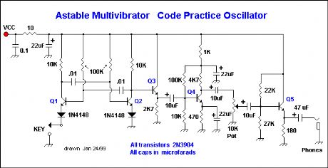
The voltage / time output waveform of the astable multivibrator is largely a square wave which some people find harsh. Many users prefer listening to a sine wave although that is beyond the scope of this web page. The multivibrator shown has real advantages in that, it is both dependable and tolerant with respect to parts substitutions. Keying the oscillator as shown practically guarantees that the multivibrator will start running each time you hit the key.
VCC can be 9 to 13.8 volts DC and the larger the voltage the greater the volume in the headphones. The B+ decoupling circuit at the top left can be omitted for battery operation or if you prefer not to bother with it. The basic multivibrator and emitter-follower circuit can be used in a transceiver as a sidetone for monitoring keying. A series resistor from the emitter-follower maybe necessary to attenuate/match the sidetone to the transceiver's AF amp.
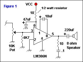
If you desire speaker level output, the Q5 common-collector final can be omitted and the circuit shown below used. This circuit uses the LM386N and provides up to ~ 0.5 watts into an 8 ohm speaker. Connect the Figure 1 circuit as shown to the 10 uF coupling capacitor connected to the collector of Q4. Do not connect the 10 ohm half-watt resistor to the decoupled VCC shown in the schematic. The power supply to the LM386N AF amp should be directly connected to the VCC, not like the common-collector AF stage shown in the schematic to the right. (View)
View full Circuit Diagram | Comments | Reading(1048)
Code Practice Oscillator
Published:2012/12/6 19:43:00 Author:muriel | Keyword: Code Practice Oscillator
View full Circuit Diagram | Comments | Reading(3560)
VFO Design
Published:2012/12/6 19:40:00 Author:muriel | Keyword: VFO Design
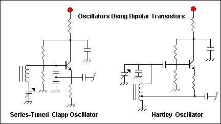
Reviewing the Amateur Radio literature revealed that JFETS enjoy tremendous popularity as the active device in LC local oscillators during the past ten years. To conform to the original design criteria of this project it was decided to build the VFO from only 2N3904s for the oscillator and the buffer sections. Four different VFO's were built and tested for short and long term frequency stability. Two partial schematics are shown below. Each design used the same buffer/amplifier for some sort of control. I found that it is possible to build very stable oscillators using the 2N3904, providing good quality, temperature-stable components are used. Careful attention to the design guidelines published by people like W1FB, W7EL and W7ZOI are mandatory. Electrical engineering knowledge would also be very helpful as I found biasing and feedback resistance values, coupling cap values and inductor Q all can have an effect on frequency stability and/or output noise.
My tests failed to determine why the JFET is so popular; there are just too many variables to factor in both electronically and through building techniques. Possibly, the easiest no-fail VFO to build is the tapped inductor Hartley using a JFET and this may help explain the popularity of the JFET.
This design was by far the most stable design for both short and long term drift and is the most stable VFO that I have ever built. The VFO will see duty as a lab oscillator for use in future projects built for the great QRP band, 30 meters.
Despite the fact that the oscillators built with the bipolar transistors were frequency stable, 1 VFO stood out -- the VFO circuit entitled: An (LC) VFO for 30 Meters (View)
View full Circuit Diagram | Comments | Reading(1715)
Band pass Filter
Published:2012/12/6 19:39:00 Author:muriel | Keyword: Band pass Filter
A band pass filter was designed for low insertion loss to help maintain the receiver noise figure. In keeping with this, NP0 ceramic capacitors were used for the 68 pF and 5 pF fixed-value capacitors. The trimmer cap was a 5 -20 pF ceramic variable with a Qu of 300. (Digi-Key bottom-adjusted SG20016-ND). The leads were bent so that each trimmer cap could be adjusted from the top. The L1 and L2 inductors were wound using 27 turns of #26 AWG enamel coated wire on T50-6 powdered iron toroids. A tap was made four turns up from the grounded end. Qu is ~ 250 for these inductors. The center frequency is 10.125 MHz, the bandwidth is 0.88 MHz and the loaded Q of the resonators is 11.5. The easiest method to tune the resonators is to peak the trimmer caps for the greatest measured output voltage using an oscilloscope. I used the receiver VFO temporarily terminated with a -10dB, 50 ohm pad to obtain the correct filter input impedance and connected it to the input end of the filter. I temporarily terminated the output of the filter with a 51 ohm resistor to ground. The VFO was tuned to the center frequency by placing it next to a receiver set on 10.125 MHz. A frequency counter can also be used. The trimmers were adjusted on each resonator to obtain the highest measured voltage possible. The filter was then placed in the receiver after removing the temporary alterations used during calibration. If you do not have access to test equipment, tune the resonators at the center frequency while listening to the receiver in the headphones to obtain the greatest possible band noise. Confirm your adjustments by tweaking the trim caps while listening to a QSO as well.
(View)
View full Circuit Diagram | Comments | Reading(1977)
30 Meter Receiver
Published:2012/12/6 1:38:00 Author:muriel | Keyword: 30 Meter, Receiver
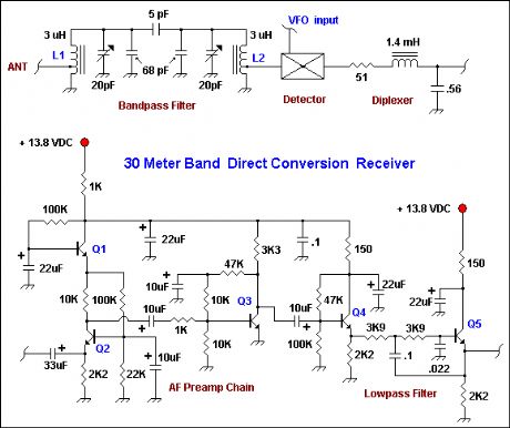
A lot can be learned when using strict design criteria to build a project. I set out to build an entire receiver using only 2N3904 transistors and at the end settled upon the design shown above. This design resembles that of the Ugly Direct receiver on this web site in a lot of ways and is also a low-cost popcorn project. A great deal of time was spent building and testing various VFO designs and investigating an interesting single-balanced mixer using two 2N3904 BJT's. The design process and reasons for abandoning my original criteria in the case of the mixer and VFO will be discussed. (View)
View full Circuit Diagram | Comments | Reading(1087)
Ugly Construction
Published:2012/12/6 1:36:00 Author:muriel | Keyword: Ugly Construction
View full Circuit Diagram | Comments | Reading(1078)
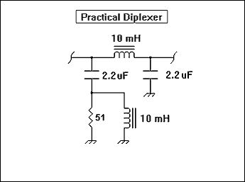
Practical Diplexer for Popcorn Receivers
Published:2012/12/6 1:35:00 Author:muriel | Keyword: Practical Diplexer , Popcorn Receivers
View full Circuit Diagram | Comments | Reading(1434)
Comments and analysis by W7ZOI
Published:2012/12/6 1:34:00 Author:muriel | Keyword: Comments , analysis, W7ZOI
View full Circuit Diagram | Comments | Reading(898)
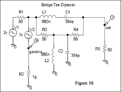
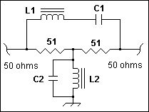
Bridge-Tee RF Diplexer
Published:2012/12/6 1:33:00 Author:muriel | Keyword: Bridge-Tee RF Diplexer
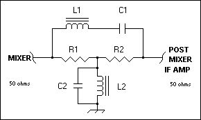
This is an excellent bandstop/bandpass diplexer popularized by Joe Reisert W1JR. This easy to build diplexer has a low parts count and is easily built using Ugly Construction. Resistors R1 and R2 present a 50 ohm impedance to the mixer output and a 50 ohm impedance to the input of the post mixer amplifier. The IF frequency is passed through the diplexer while out of passband RF is given a low impedance path to ground. The capacitance for C1 is generally built up by substituting the nearest standard value capacitor or by placing 2 or more capacitors in parallel with each other to achieve the desired value. The same procedure is then repeated for the C2 capacitance. For more strenuous purposes, a portion of C1 and C2 or the inductors L1 and L2 can be variable and adjusted on the bench. The inductors can easily wound on powdered-iron toroid cores. I have used T50-2 or T50-6 type toroids with good results. The Q of the inductors is 1.It is possible to design a more generalized form of this diplexer with a higher loaded Q in the resonators. The diplexer shown and used in the program has a Q of 1. This was used by W1JR in his VHF/UHF World Column in the now defunct HAM Radio Magazine for March and November 1984. It was also more recently used by Jacob Makhinson, N6NWP in his A High-Dynamic Range MF/HF Receiver Front End in QST for February 1993. The actual formulae for this diplexer is far more complex than the simplified formula shown below or used in the program, but both provide a very good approximation for the Q = 1 version as used by W1JR and N6NWP. If you wanted Q=10, the series tuned circuit would use L that is 10 times as high with C to resonate. The parallel tuned circuit would then use C that was 10 times higher with L to resonate. A supplemental web page with some hard-core mathematics for this diplexer can be found on the Diplexer Supplemental Page. (View)
View full Circuit Diagram | Comments | Reading(2962)
W7ZOI Diplexer
Published:2012/12/6 1:33:00 Author:muriel | Keyword: W7ZOI Diplexer
View full Circuit Diagram | Comments | Reading(1567)
Homebuilding Diode Ring Mixers
Published:2012/12/6 1:31:00 Author:muriel | Keyword: Homebuilding Diode Ring, Mixers
View full Circuit Diagram | Comments | Reading(2233)
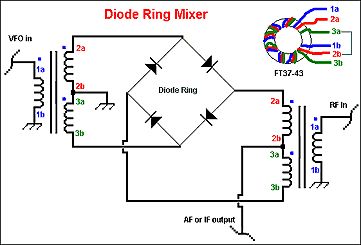
Broadband Transformers plus Diode Ring Mixers
Published:2012/12/6 1:30:00 Author:muriel | Keyword: Broadband Transformers, Diode Ring Mixers
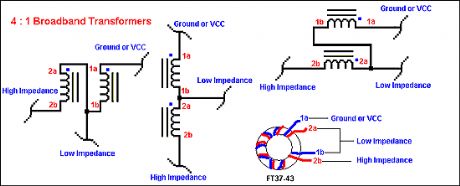
There are 2 basic types of broadband transformers used in most QRP work — conventional and transmission line style. Both types may be wound on ferrite toroids, pot cores or rods, however, I only discuss the toroidal transformers we employ to give a 4:1 impedance transformation.
I use these transmission line transformers on many projects on the QRP / SWL HomeBuilder web site. For MF and HF uses, a ferrite core permeability of 850-900 is generally required and the FT37-43 ferrite core proves suitable. Shown above are 3 equivalent schematics of the 4:1 transmission line transformer. You'll probably find that the center drawing easiest to conceptualize, however, with closer examination, all 3 schematics are the same and transform signals from unbalanced 50 Ω impedance up to 200 Ω unbalanced impedance or visa-versa.
The high impedance is 200 Ω and the low impedance is 50 Ω in all cases. It is important to know that these transformers are symmetrical and the points labeled Ground or VCC can be switched with the point labeled High Impedance. (View)
View full Circuit Diagram | Comments | Reading(1558)
Popcorn Direct Conversion Main Frame
Published:2012/12/6 1:28:00 Author:muriel | Keyword: Popcorn Direct Conversion, Main Frame
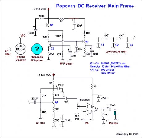
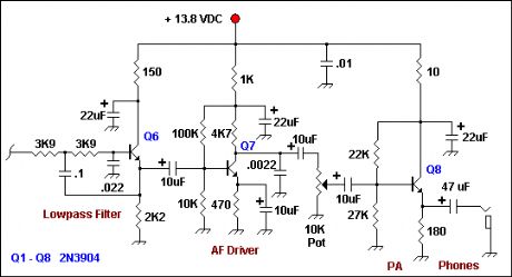
Shown to the right is the schematic to a low cost popcorn direct conversion receiver main frame. To complete the receiver, a front end band pass filter and a VFO with an output power of 7 dBm is required. This is indeed a frugal project using 4 cheap transistors, an RC low pass filter and an LM386N for output power to a pair of low-impedance headphones. The builder also has a choice of 5 diplexers and an optional mute circuit. This receiver is easily built using Ugly Construction and can be built in 3-4 hours with a bit of luck. (View)
View full Circuit Diagram | Comments | Reading(983)
Universal Diplexer
Published:2012/12/6 1:25:00 Author:muriel | Keyword: Universal Diplexer
Universal Diplexer calculates the inductance and capacitance values for a Bridge-Tee diplexer based upon a chosen superhet receiver intermediate frequency. The diplexer is the Joe Reisert, W1JR popularized design discussed under Diplexer Topics on this web site. The user inputs an IF and presses the Calculate button to have the capacitor and inductor values given in pF and uH respectively. The diplexer schematic is included in the application. Note that the this is for the Q = 1 version of the Bridge-Tee Diplexer. (View)
View full Circuit Diagram | Comments | Reading(1152)
PI Filter Designer
Published:2012/12/6 1:24:00 Author:muriel | Keyword: PI Filter Designer
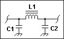
PI Filter Designer is a simple 3 element 50 ohm input and output impedance pi filter designing application. This program allows the user to design simple lowpass filters by selecting from a variety of standard capacitor values either empirically or to suit what you have on hand. The filter 3 dB cutoff frequency and required L1 inductance are automatically calculated and displayed. In addition, the user may select an additional capacitor value to put in parallel with both caps C1 and C2. In this app XL = XC = 50 ohms impedance. No other impedances can be calculated with this program. (View)
View full Circuit Diagram | Comments | Reading(727)
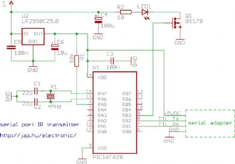
Computer controlled infrared transmitter
Published:2012/12/6 1:15:00 Author:muriel | Keyword: Computer controlled , infrared transmitter
View full Circuit Diagram | Comments | Reading(1032)
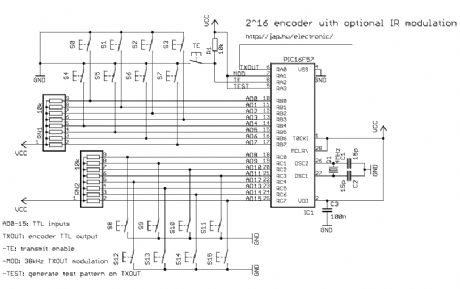
2^12 encoder
Published:2012/12/6 1:11:00 Author:muriel | Keyword: 2^12 encoder
View full Circuit Diagram | Comments | Reading(1108)
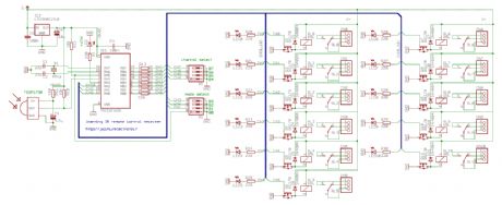
Learning IR remote control receiver
Published:2012/12/6 1:10:00 Author:muriel | Keyword: Learning IR , remote control , receiver
View full Circuit Diagram | Comments | Reading(1281)
| Pages:25/195 At 202122232425262728293031323334353637383940Under 20 |
Circuit Categories
power supply circuit
Amplifier Circuit
Basic Circuit
LED and Light Circuit
Sensor Circuit
Signal Processing
Electrical Equipment Circuit
Control Circuit
Remote Control Circuit
A/D-D/A Converter Circuit
Audio Circuit
Measuring and Test Circuit
Communication Circuit
Computer-Related Circuit
555 Circuit
Automotive Circuit
Repairing Circuit