
Signal Processing
Index 39
Multi-Instrument Melody Generator UM34811A
Published:2012/9/12 21:02:00 Author:Ecco | Keyword: Multi-Instrument, Melody Generator
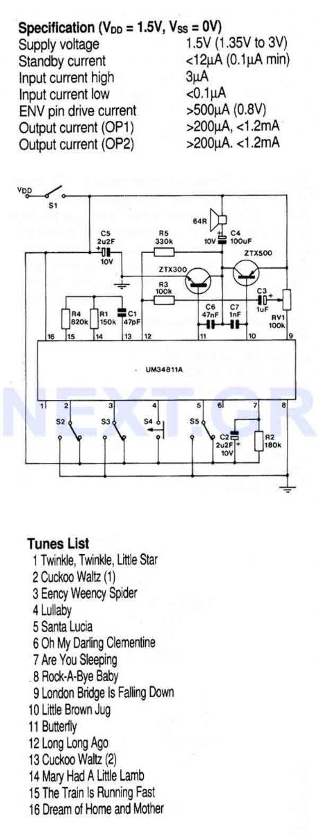
This circuit is based on a preprogrammed multi-instrument melody generator IC, containing a 512-note memory capable of generating 16 tunes. The comprehensive control facilities enable playing - all tunes repeatedly or stopping at the end, - or one tune repeatedly or stopping at the end.
Source: NEXT.GR (View)
View full Circuit Diagram | Comments | Reading(1310)
Waveform Generator with ICL 8038CCPD
Published:2012/9/12 21:01:00 Author:Ecco | Keyword: Waveform Generator , ICL
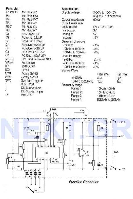
That circuit is based on a 14-pin DIL IC capable of producing sine, square, triangular, sawtooth and pulse waveforms of high accuracy and stability. The frequency may be selected to be from 0.001Hz to 1Mhz, Frequency modulation and sweeping can be accomplished with an external voltage and the frequency can be programmed digitally by resistors or capacitors. Sweep range can be up to 40:1 or 1000:1 with a little less quality.
Source: NEXT.GR (View)
View full Circuit Diagram | Comments | Reading(1837)
555 Audio Oscillator
Published:2012/9/10 21:14:00 Author:Ecco | Keyword: 555 , Audio , Oscillator
A oscilloscope would be useful in analyzing the waveforms produced by this circuit, but it is not essential. An audio detector is a very useful piece of test equipment for this experiment, especially if you don't have an oscilloscope.
Source: discovercircuits (View)
View full Circuit Diagram | Comments | Reading(699)
Precision 40KHz Triangle Generator
Published:2012/9/10 20:44:00 Author:Ecco | Keyword: Precision , 40KHz, Triangle Generator
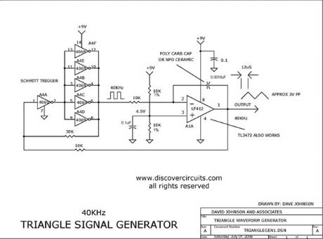
This circuit generates a precision 40KHz triangle waveform.
Source: discovercircuits (View)
View full Circuit Diagram | Comments | Reading(1796)
CMOS INVERTER PARALLEL LC OSCILLATOR
Published:2012/9/9 21:15:00 Author:Ecco | Keyword: CMOS , INVERTER , PARALLEL , LC OSCILLATOR
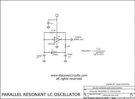
I have used this parallel resonant LC oscillator circuit countless times. The oscillator frequency is determined by the inductor and capacitor values. I have shown an adjustable inductor to make it easy to set the frequency to a specific value. Once set the frequency is fairly stable over supply voltage variations and temperature changes. The values shown are for 125KHz but the frequency can range from tens of kilohertz to tens of megahertz. With a 74HCU04 type inverter, it will oscillate down to about 1.5 volts. If the frequency is low, you can also use a 74C04 (CD4069) inverter.
Source: discovercircuits (View)
View full Circuit Diagram | Comments | Reading(3972)
AUDIO FREQUENCY DIGITAL NOISE GENERATOR
Published:2012/9/9 20:56:00 Author:Ecco | Keyword: AUDIO FREQUENCY, DIGITAL , NOISE GENERATOR
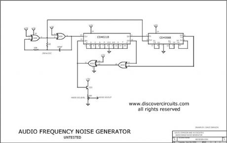
When you need to test an audio circuit with broadband noise, this circuit works great. It uses just three inexpensive C-MOS ICs that generate a series of output pulses whose widths vary randomly. I included a level control pot.
Source: discovercircuits (View)
View full Circuit Diagram | Comments | Reading(0)
Ultra Low Current Oscillator (February 17, 2009)
Published:2012/9/9 20:51:00 Author:Ecco | Keyword: Ultra Low Current, Oscillator
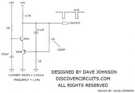
Here is a challenge. Design an astable oscillator which draws only a few nanoamps of current from a +3v supply. I gave this some thought and came up with the circuit below. I used some pretty standard parts except for three surface mounted 1000M resistors I had on hand. The oscillator frequency measured a low 1Hz frequency and the average current was a very low 3 nanoamps. If I had some higher resistors values handy, I think I could have gotten the current down below one nanoamp.
Source: discovercircuits (View)
View full Circuit Diagram | Comments | Reading(1685)
Low Power Oscillators
Published:2012/9/9 20:34:00 Author:Ecco | Keyword: Low Power , Oscillators
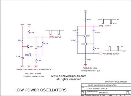
This page has two unusual two-transistor oscillators. I set the component values for a low frequency application. Both circuits draw only about 1 microamp of current.
Source: discovercircuits (View)
View full Circuit Diagram | Comments | Reading(1572)
Delayed Pulse Generator
Published:2012/9/9 20:31:00 Author:Ecco | Keyword: Delayed , Pulse , Generator
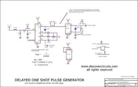
This circuit generates a short 10ms pulse 15 minutes after a ?start? pushbutton switch is activated. (added 12/04)
Source: discovercircuits (View)
View full Circuit Diagram | Comments | Reading(0)
Bathroom door controlled switch circuit (4)
Published:2012/9/6 21:55:00 Author:Ecco | Keyword: Bathroom door , controlled, switch
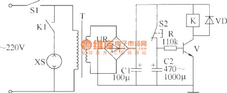
The circuit is simple, easy to make without debugging, and it can be used for bathroom exhaust fan controlling. The bathroom door controlled switch circuit consists of power circuit and control circuit, and it is shown in the figure.
R selects 1/4W carbon film resistor or metal film resistor.C1 and C2 select aluminum electrolytic capacitors with voltage in 16V.VD uses 1N4001 or 1N4007 silicon rectifier diodes.UR selects 1A , 50V rectifier bridge pile.V uses C8050, S8050 or 3DG8050 silicon NPN transistor.T chooses 3W power transformer with 9V secondary voltage.K selects 4098 9V DC relay.S1 is theoriginal ventilator outlet's power switch; S2is broken (normally closed ) micro switch or button.
(View)
View full Circuit Diagram | Comments | Reading(968)
SIMPLE NITROGEN SPARK GENERATOR
Published:2012/9/6 20:26:00 Author:Ecco | Keyword: SIMPLE, NITROGEN SPARK GENERATOR
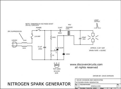
Nitrogen or air sparks are very powerful light sources that produce flashes that last only a few nanoseconds. This line-powered circuit generates a continuous series of very small sparks across electrodes with a 0.05-inch gap.
Source: discovercircuits (View)
View full Circuit Diagram | Comments | Reading(4529)
Wave Power Generator Demo System
Published:2012/9/6 20:23:00 Author:Ecco | Keyword: Wave Power Generator, Demo System
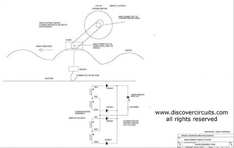
An inexpensive stepper motor is used as a voltage generator in this wave generator demo.
Source: discovercircuits (View)
View full Circuit Diagram | Comments | Reading(0)
AUDIO FREQUENCY DIGITAL NOISE GENERATOR
Published:2012/9/5 21:03:00 Author:Ecco | Keyword: AUDIO , FREQUENCY , DIGITAL , NOISE GENERATOR

When you need to test an audio circuit with broadband noise, this circuit works great. It uses just three inexpensive C-MOS ICs that generate a series of output pulses whose widths vary randomly. I included a level control pot.
Source: discovercircuits (View)
View full Circuit Diagram | Comments | Reading(4901)
Low Power Oscillator
Published:2012/9/5 20:55:00 Author:Ecco | Keyword: Low Power, Oscillator

This page has two unusual two-transistor oscillators. I set the component values for a low frequency application. Both circuits draw only about 1 microamp of current.
Source: discovercircuits (View)
View full Circuit Diagram | Comments | Reading(1455)
Ultra Low Power 32KHz Crystal Oscillator
Published:2012/9/5 20:34:00 Author:Ecco | Keyword: Ultra Low Power, 32KHz, Crystal Oscillator
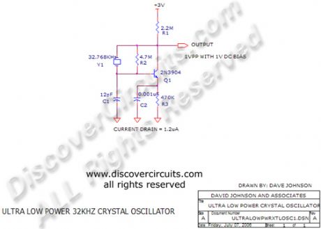
I have used this circuit many times when I needed a low frequency reference, which did not draw much power. With the components show, the current from a 3v battery is less than 1.2 microamps
Source: discovercircuits
(View)
View full Circuit Diagram | Comments | Reading(1693)
VERY LOW POWER GATED CRYSTAL OSCILLATOR
Published:2012/9/4 20:55:00 Author:Ecco | Keyword: VERY LOW , POWER GATED , CRYSTAL OSCILLATOR
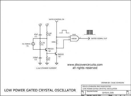
The circuit gates the output of a continuously operating 32KHz crystal oscillator to the input of a C-MOS buffer when clock pulses are needed. The technique gets around the problem of a slow starting crystal oscillator by keeping the oscillator going and switching on a transistor power stage only as needed. The method keeps the standby power consumption to a very low 1uA when used with a 3v supply.
Source: discovercircuits (View)
View full Circuit Diagram | Comments | Reading(3211)
Fully Isolated 50/60Hz Sync Generator
Published:2012/9/4 20:43:00 Author:Ecco | Keyword: Fully Isolated , 50/60Hz , Sync Generator
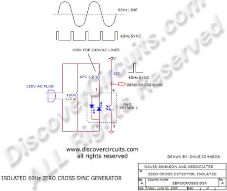
This circuit will produce a single pulse at the zero voltage cross points of the power line voltage. An opto-coupler provides a very safe 5KV isolation.
Source: discovercircuits (View)
View full Circuit Diagram | Comments | Reading(1192)
Two -phase oscillator circuit diagram
Published:2012/8/30 1:47:00 Author:Ecco | Keyword: Two -phase oscillator
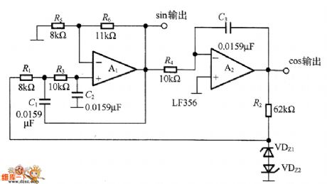
In the circuit, it is composed of op-amps A1 and A2, etc., and the op-amp A1 is a low-pass filter, A2 is an integrator, and each phase lag 90 °, the total phase lag is 180 °. The oscillation frequency is determined by R1 + R2, R3, R4 , C1, and C2, and C3. According to the parameters of FIG, the oscillation frequency is 1 kHz. The regulator tubes VDz1 VDz2 are mainly used to stabilize the amplitude, but in order to reduce the distortion of the waveform, it must choose two regulators with the same characteristics. The distortion of the cosine (cos) output waveform in the circuit is controlled at 0.3% or less, and the distortion of sine (sin) output waveform is about 1%.
(View)
View full Circuit Diagram | Comments | Reading(1520)
Oscillator circuit diagram with triangle-wave/square wave output
Published:2012/8/30 1:29:00 Author:Ecco | Keyword: Oscillator, triangle wave, square wave
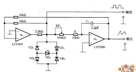
The circuit is composed of lag comparator with A1 and inverting integrator A2, and the charging and discharging time constant is decided by integral resistors (R1+RP1) and the capacitor C1. VD1~VD5 form the limiter circuit. The maximum oscillation frequency is related to swicthing rate of amplifier, when swicthing rate is 10V/μ s, in order to get the 20V (peak-peak) triangle wave, it must have at least 2 μ s lag, even up to 20 μ s, therefore, in order to increase the frequency of oscillation, A1 and A2 should select high speed operational amplifier.
(View)
View full Circuit Diagram | Comments | Reading(3148)
1000 m single-tube oscillation (C8050) FM transmitter circuit
Published:2012/8/27 22:27:00 Author:Ecco | Keyword: 1000 m , single-tube oscillation , FM transmitter
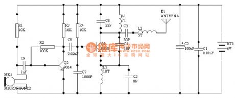
The circuit is very simple without debugging, you just need to make sure components are well connected without rosin joint and short circuit, it can work properly. Its power is about 60mw, so it is generally recommended to use rechargeable batteries which not only can provide large current, and be economy, and it is the ideal choice. But I do not advocate the transformer power supply, because it needs high filter circuit.
(View)
View full Circuit Diagram | Comments | Reading(2819)
| Pages:39/195 At 202122232425262728293031323334353637383940Under 20 |
Circuit Categories
power supply circuit
Amplifier Circuit
Basic Circuit
LED and Light Circuit
Sensor Circuit
Signal Processing
Electrical Equipment Circuit
Control Circuit
Remote Control Circuit
A/D-D/A Converter Circuit
Audio Circuit
Measuring and Test Circuit
Communication Circuit
Computer-Related Circuit
555 Circuit
Automotive Circuit
Repairing Circuit