
Signal Processing
Index 40
PRTD signal conditioning circuit composed of multi-functional sensor signal conditioner AD693
Published:2012/8/27 1:38:00 Author:Ecco | Keyword: PRTD , signal conditioning , multi-functional sensor, signal conditioner
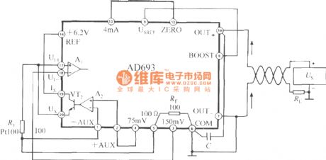
Platinum thermal resistor is a common temperature sensor, and there is a linear relationship between RT and temperature. AD693 has the the Pt100 platinum thermal resistance interface, which can be configured directly as PRTD signal conditioner, and the circuit is shown in Fig. Pt100's resistance value is 100Ω at 0℃, and the resistance change rate TCR = 0.00385Ω / Ω / ℃. The resistor can convert the temperature in range of 0 ~ +104 ℃ into 4 ~ 20mA current to complete temperature / current (T / I) conversion. The AD693 can set 6 different temperature ranges to meet the needs of different users.
(View)
View full Circuit Diagram | Comments | Reading(2213)
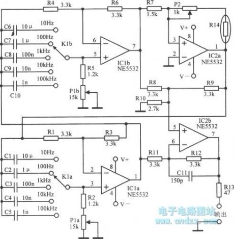
High-performance audio oscillator
Published:2012/8/27 1:02:00 Author:Ecco | Keyword: High-performance audio oscillator
View full Circuit Diagram | Comments | Reading(1244)
Harmonic generator circuit
Published:2012/8/22 20:33:00 Author:Ecco | Keyword: Harmonic generator
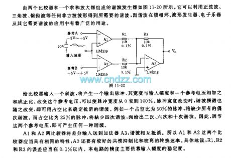
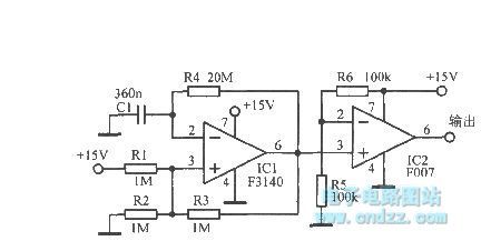
The harmonics generator composed by the two comparators and a summing amplifier is shown in Fig 11-20. It can use any non- square wave including sine, triangle, sawtooth waveform to get harmonic, and harmonic is widely used in phase-locked loop, waveform generator, electronic musical instruments and other harmonic applications. When the comparator is input a harmonic, it will produce an output pulse, the width is proportional to the sum of input amplitude and reference voltage. Changing the reference voltage can allow the pulse width to change between from 0 to 100 %. The harmonic spectrum changes with pulse width, you can use the duty cycle to determine the offset harmonic.
(View)
View full Circuit Diagram | Comments | Reading(1257)
Low frequency oscillator circuit with TcA580
Published:2012/8/22 20:18:00 Author:Ecco | Keyword: Low frequency , oscillator
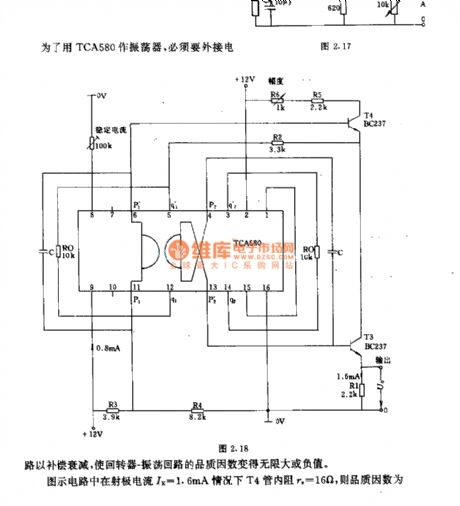

In order to use TCA580 as oscillator, the circuit must connect an external circuit for attenuation, then the loop - oscillation loop's quality factor becomes infinite or negative. In the circuit shown as the figure, when emitter current IE =1.6mA, internal resistance of T4 tube re= 16Ω.
(View)
View full Circuit Diagram | Comments | Reading(1472)
A variety of sound effects generator circuit
Published:2012/8/21 22:18:00 Author:Ecco | Keyword: variety , sound effects , generator
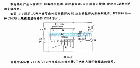
This circuit can produce eight kind of sounds, namely two kinds of machine gunfire, two kinds of bomb sound, dual tone music melody, game sound, animal calls and the sound of rifle shot. As shown in figure 10-6, eight kinds of sound can be played respectively by switching rotary switch S2 and pushing button switch. HT2880 is a kind of CMOS large-scale ROM chip. The transistors VT1 and VT2 in circuit are connected as Darlington pipe which is used to amplify the signal output from pin 4.
(View)
View full Circuit Diagram | Comments | Reading(1414)
Rain sound generator circuit
Published:2012/8/21 22:43:00 Author:Ecco | Keyword: Rain sound generator
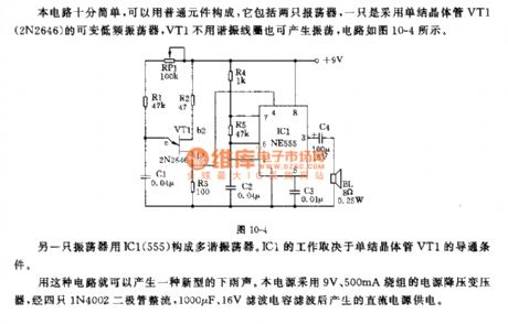
The circuit is very simple, and it is composed of common elements, it includes two oscillators: one is a variable low frequency oscillator which uses single-junction transistor VT1 (2N2646), VT1 can generate oscillation circuit without resonant coil, the circuit is shown in Figure 10-4. The other oscillator and IC1 (555) constitute a multivibrator. IC1 work depends on the conduction conditions of the single-junction transistor VT1. This circuit can produce a new type of rain sound. The power supply uses 9V, 500mA winding power step-down transformer, and the power is rectified by four 1N4002 diode, filtered by 1000μF and 16V filter capacitor to become DC power supply.
(View)
View full Circuit Diagram | Comments | Reading(1686)
Ultra-low frequency multivibrator
Published:2012/8/21 22:46:00 Author:Ecco | Keyword: Ultra-low frequency , multivibrator
View full Circuit Diagram | Comments | Reading(769)
The lc wobbulator circuit with varactor diode
Published:2012/8/21 21:27:00 Author:Ecco | Keyword: lc wobbulator , varactor diode
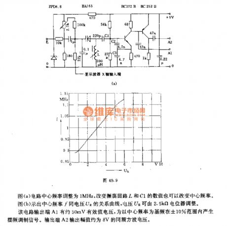
Figure (a) shows the circuit with center frequency being adjusted to 1MHz, center frequency can also be changed by the oscillation circuit L and the value of C1.Figure (b) shows the curve between the center frequency f and voltage UR, voltage UR can be adjusted by 2.5kΩ potentiometer.The circuit output terminal A1 has about 50mV RMS voltage, the center frequency will generate modulated signal in the he baseband pendulum frequency range of ± 10%. The output terminal A2 has the same frequency square wave voltage with 8V output amplitude.
(View)
View full Circuit Diagram | Comments | Reading(2188)
Pulse keying ring oscillator
Published:2012/8/21 22:08:00 Author:Ecco | Keyword: Pulse, keying, ring , oscillator
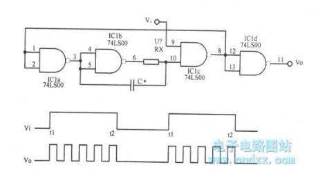
View full Circuit Diagram | Comments | Reading(1451)
Gate voltage generator circuit
Published:2012/8/21 22:01:00 Author:Ecco | Keyword: Gate voltage generator
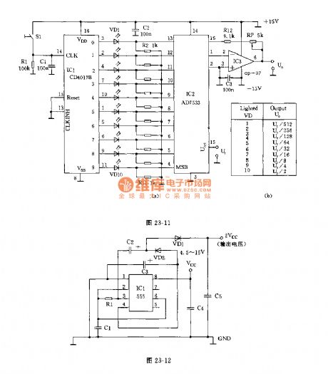
FET is commonly used in low-power instruments. When it works, the gate voltage should be higher than the source voltage 9V, it is inconvenient to use battery-powered low-voltage circuit.Working principle: the circuit is shown in Figure 23-12. This circuit can provide high gate voltage. 555 oscillator drives a voltage multiplier to produce the output voltage which is twice of the input voltage. Generally FET ignores gate current, the output current of circuit is very small, and it can provide gate voltage to the 10 FETs without voltage drop at the same time.
(View)
View full Circuit Diagram | Comments | Reading(1099)
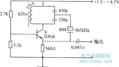
The circuit of 100kHz oscillator
Published:2012/8/21 3:40:00 Author:Ecco | Keyword: 100kHz oscillator

The circuit uses a standard quartz crystal oscillator SQ4804A, and the bias between output frequency and standard frequency does not exceed 100 × 10-6. The oscillator control the following amplifier (BC108) to output square wave, and it uses the integral circuit to obtain up to 8 branches of output, then to control the eight gates.
(View)
View full Circuit Diagram | Comments | Reading(2587)
1kHz to 1MHz sine oscillator circuit
Published:2012/8/21 21:03:00 Author:Ecco | Keyword: 1kHz to 1MHz , sine oscillator
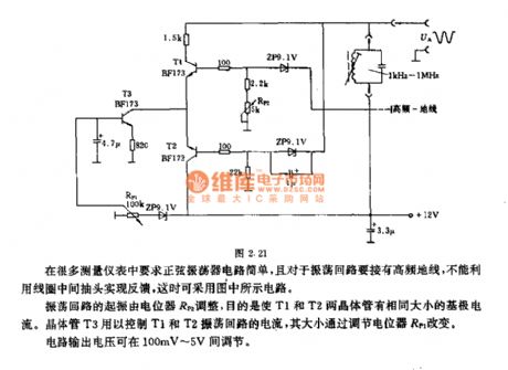
Sinusoidal oscillator circuit issimple in many measuring instrument, and oscillation loop should be connected to a high-frequency ground, and it can not use the coil center tap to achieve the feedback, in this case it can use the circuit shown as figure. The oscillation starting of shock drop is adjusted by potentiometer RP2, the purpose is to make T1 and T2 transistors have the same base current. Transistor T3 is used for controlling the current of T1 , T2 oscillation loop, and its size is changed by adjusting potentiometer RP1. Circuit output voltage can be adjusted between 100mV ~ 5V.
(View)
View full Circuit Diagram | Comments | Reading(1535)
Astable flip-flop ( multivibrator ) circuit
Published:2012/8/21 20:25:00 Author:Ecco | Keyword: Astable flip-flop , multivibrator
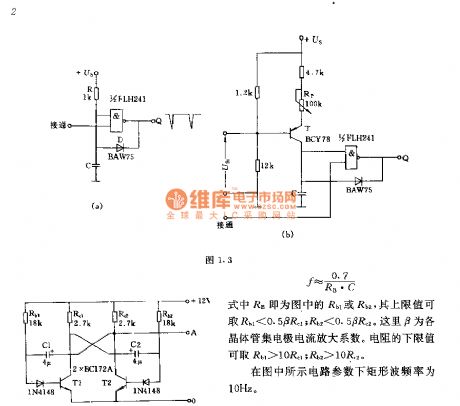
The two parts' component parameters and models of the circuit are corresponding to simultaneously obtain a rectangular wave with duty ratio of 1:1, its frequency f = 0.7/RB • C. RB is Rb1 or Rb2 in the figure, and its upper limit value Rb1 < 0.5βRC1 ; Rb2 < 0.5βRC2, here β is the transistor collector current amplification factor. The lower limit value of the resistor is Rb1 > 10βRC1 ; Rb2 > 10βRC2, the of rectangular wave frequency under circuit parameters shown in figure is 10Hz.
(View)
View full Circuit Diagram | Comments | Reading(1928)
Trapezoidal wave generator ( Figure 1.7 ) circuit
Published:2012/8/21 20:12:00 Author:Ecco | Keyword: Trapezoidal wave, generator

Trapezoidal wave's time t1 ~ t4 can be independently adjusted. Time t1 can be coarse tuned by capacitor C1 and fine tuned by potentiometer Rp. T2 is coarse and fine tuned by C2 and R2. t1 + t2 determines the period or frequency. t3 is changed by the potentiometer RP3, and its value is calculated according to t3 = CRE • UA / UE. RE is PNP transistor emitter resistance, UE is emitter voltage drop, UA is the magnitude of output voltage.
(View)
View full Circuit Diagram | Comments | Reading(1549)
Oscillator for electronic musical instruments
Published:2012/8/21 3:48:00 Author:Ecco | Keyword: Oscillator , electronic musical instruments
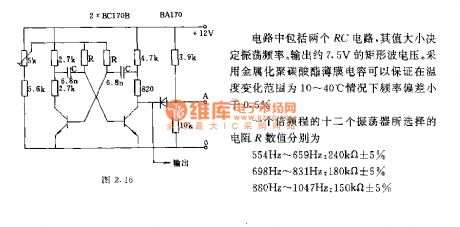
The circuit comprises two RC circuits, the value can determine the oscillation frequency. The output rectangular wave voltage is approximately 7.5V. It uses metallized polycarbonate film capacitor to guarantee that the frequency deviation is less than 0.5% in the temperature range of 10 ~ 40 ℃. The R values of 12 oscillators in an octave process are selecting as below.
(View)
View full Circuit Diagram | Comments | Reading(1010)
Common-base quartz controlled frequency capacitance feedback oscillator
Published:2012/8/21 20:02:00 Author:Ecco | Keyword: Common-base , quartz , controlled frequency , capacitance feedback , oscillator
View full Circuit Diagram | Comments | Reading(1019)
The LC oscillator circuit for electronic cello
Published:2012/8/21 20:00:00 Author:Ecco | Keyword: LC oscillator , electronic cello
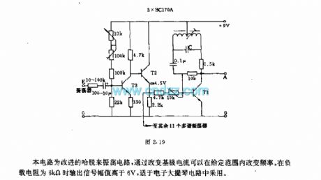
This circuit is the improved hartley oscillator circuit, changing the base current can adjust the frequency in a given range. The output signal amplitude is higher than 6V in 6kΩ load resistance,and it is suitable for electronic cello circuits.
(View)
View full Circuit Diagram | Comments | Reading(1929)
Frequency and time signal generator circuit
Published:2012/8/15 22:38:00 Author:Ecco | Keyword: Frequency , time, signal, generator
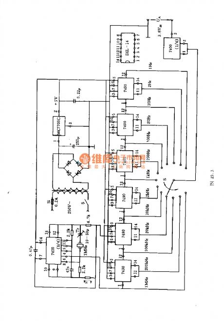
The circuit uses a 7490 four asynchronous counter (including four flip-flopS ) to form two-frequency divider and five-frequency divider by an external programmer. The time-base circuit is compoaed of two NAND gates and crystal, and the divider uses 13-position switch S to choose different frequency. The output voltage has a TTL- level, which is approximately 3.8V.
(View)
View full Circuit Diagram | Comments | Reading(1703)
TDA8305A AGC and line / field scanning signal processing integrated circuit diagram
Published:2012/8/16 22:10:00 Author:Ecco | Keyword: medium , line , field scanning , signal processing, integrated circuit
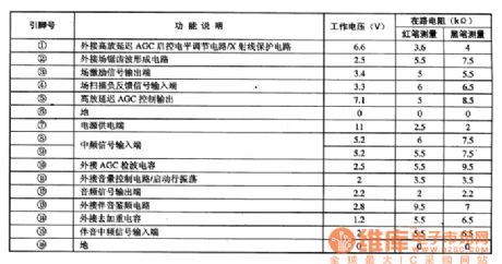
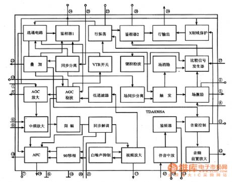
TDA8305A is the image, AGC and line, field scanning samll-signal processing integrated circuit produced by Philips, and it is widely used in the Philips series of large-screen movements, color TVs.TDA8305A integrated circuit includes: image IF amplifier, AGC amplifier, AGC detector circuit, AGC control circuit; audio amplifier circuit, frequency discriminator, volume control, audio preamplifier circuit; sync separation circuit, phase detector circuit; line oscillation circuit, output circuit, X -ray protection circuit; field excitation circuit and its subsidiary circuits. Its internal block diagram is shown in Figure 1. TDA8305A IC uses 28-pin double row of plug-in package, and the pin functions and data are shown in Table 1.
(View)
View full Circuit Diagram | Comments | Reading(2155)
Nanosecond pulse integrating circuit composed of broadband transconductance operational amplifier buffer OPA660
Published:2012/8/15 1:46:00 Author:Ecco | Keyword: Nanosecond , pulse , integrating circuit , broadband transconductance , operational amplifier, buffer
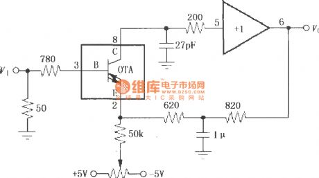
The input signal VI is added to the pin 3 of OPA660 by 780Ω base resistor and 50Ω matched resistor, then it will be output by pin 6 after being amplified by internal OTA and +1 amplifier. At the same time, pin 6 get feedback to pin 2 of OPA660 by integral circuit composed of the 820Ω resistor, 1μF capacitor, therefore to constitute a nanosecond pulse integrating circuit. Potentiometer can adjust the DC voltage of pin 2 to play a role in controlling the starting point of the integrator voltage.
(View)
View full Circuit Diagram | Comments | Reading(1035)
| Pages:40/195 At 202122232425262728293031323334353637383940Under 20 |
Circuit Categories
power supply circuit
Amplifier Circuit
Basic Circuit
LED and Light Circuit
Sensor Circuit
Signal Processing
Electrical Equipment Circuit
Control Circuit
Remote Control Circuit
A/D-D/A Converter Circuit
Audio Circuit
Measuring and Test Circuit
Communication Circuit
Computer-Related Circuit
555 Circuit
Automotive Circuit
Repairing Circuit