
Signal Processing
Index 26
4/8-channel V4.2 infrared receiver
Published:2012/12/5 0:15:00 Author:muriel | Keyword: 4/8-channel, V4.2 , infrared receiver
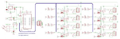
The difference between the 4-channel and the 8-channel version is only the software inside. The 8-channel receiver outputs are individually configurable for latched or momentary output. The 4-channel receiver has two outputs per channel: K1-K4 are latched outputs, K5-K8 are momentary outputs for the four channels. The valid LED shows the transmitter activity. Make sure to turn on all address jumpers when the transmitter diodes are absent, or the J1-J4 jumpers are cut. Choose V+ supply voltage between +6-15VDC, based on the relay voltage ratings. For 6V relays, use +6VDC, for 12V relays use +12VDC. (View)
View full Circuit Diagram | Comments | Reading(1116)
4/8-channel V4.2 radio receiver
Published:2012/12/5 0:14:00 Author:muriel | Keyword: 4/8-channel, V4.2, radio receiver
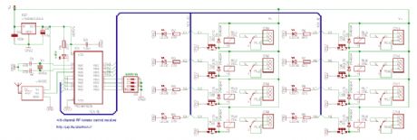
The difference between the 4-channel and the 8-channel version is only the software inside. The 8-channel receiver outputs are individually configurable for latched or momentary output. The 4-channel receiver has two outputs per channel: K1-K4 are latched outputs, K5-K8 are momentary outputs for the four channels. The valid LED shows the transmitter activity. Make sure to turn on all address switches when the transmitter diodes are absent, or the J1-J4 jumpers are cut. Choose V+ supply voltage between +6-15VDC, based on the relay voltage ratings. For 6V relays, use +6VDC, for 12V relays use +12VDC. (View)
View full Circuit Diagram | Comments | Reading(1283)
4/8-channel V4.2 infrared transmitter
Published:2012/12/5 0:12:00 Author:muriel | Keyword: 4/8-channel, V4.2, infrared transmitter
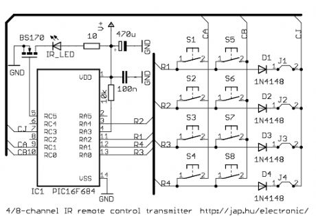
The difference between the 4-channel and the 8-channel version is only the software inside. The 8-channel transmitter has one button (S1-S8) per channel. The 4-channel transmitter uses S1-S4 buttons to turn on, S5-S8 buttons to turn off channel 1-4 (use with latched outputs on the receiver). The D1-D4 diodes and J1-J4 jumpers are optional, and are used to setup the transmitter address. V+ supply voltage should be between 2.5-5.5VDC. It is practical to use two or three AAA batteries. (View)
View full Circuit Diagram | Comments | Reading(699)
4/8-channel V4.2 radio transmitter
Published:2012/12/5 0:11:00 Author:muriel | Keyword: 4/8-channel, V4.2 , radio transmitter
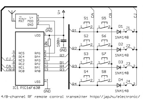
The difference between the 4-channel and the 8-channel version is only the software inside. The 8-channel transmitter has one button (S1-S8) per channel. The 4-channel transmitter uses S1-S4 buttons to turn on, S5-S8 buttons to turn off channel 1-4 (use with latched outputs on the receiver). The D1-D4 diodes and J1-J4 jumpers are optional, and are used to setup the transmitter address. Higher supply voltage resultshighertransmit power, but V+ range is 2-5.5VDC for the PIC MCU. When V+ is higher than 5VDC, use separate power for the mcu. (View)
View full Circuit Diagram | Comments | Reading(1003)
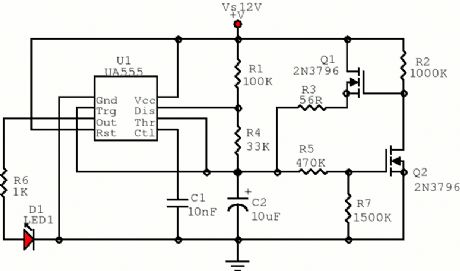
555 Pulse Generator
Published:2012/12/5 0:03:00 Author:muriel | Keyword: 555 Pulse Generator
View full Circuit Diagram | Comments | Reading(0)
Low Frequency Oscillator
Published:2012/12/4 23:48:00 Author:muriel | Keyword: Low Frequency Oscillator

A low frequency test oscillator for testing tone controls and experimenting. (View)
View full Circuit Diagram | Comments | Reading(2024)
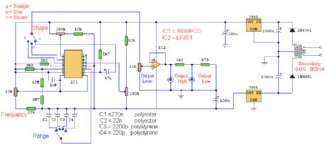
Function generator circuit diagram with ICL8038
Published:2012/12/4 21:35:00 Author:Ecco | Keyword: Function generator
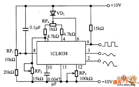
The circuit can get square wave, triangle wave and sine wave. And the triangular wave is directly formed by a capacitance constant current charging and discharging, the square wave is obtained by the control signal, and the sine wave is obtained by a triangular wave passing a fold line. Therefore, sine wave here is not a smooth curve, distortion is about t%, but it is sufficient for general use. As shown in figure, it uses ICL8038 function generator circuit. In the circuit, RP1 is used to adjust the frequency, it should use good quality potentiometer with adjustable frequency between 20Hz ~ 20kHz. The RP3 is used to adjust the degree of distortion, RP4 is used to adjust the duty cycle.
(View)
View full Circuit Diagram | Comments | Reading(14838)
Easy making negative ion generator circuit
Published:2012/12/4 21:27:00 Author:Ecco | Keyword: Easy making, negative ion generator
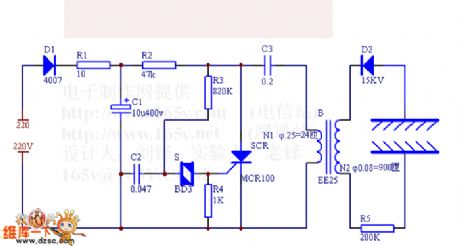
Simple negative ion generator can increase negative ions, which can help people with hypnotic, antiperspirant, analgesic, increase appetite functions, and it can eliminate fatigue.
220V AC mains is rectified by D1, then it charges for C3 and C2, when C2 is charged to the the neon bulb conduction to trigger SCR conduction, C3 discharges the SCR, B's L1 discharges, after B inductive boost, the 8kV DC high voltage reversed and rectified by D2 can make generator M molecular ionization to produce negative ions.
(View)
View full Circuit Diagram | Comments | Reading(7329)
Signal Tracer and Injector
Published:2012/12/3 20:42:00 Author:muriel | Keyword: Signal Tracer, Injector
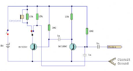
A simple test circuit to fault find audio and radio equipment. Can be used to inject a square wave signal, rich in harmonics, or used with headphones as an audio tracer.
(View)
View full Circuit Diagram | Comments | Reading(1228)
Sine Wave Generator
Published:2012/12/3 20:40:00 Author:muriel | Keyword: Sine Wave Generator

A classic Wien Bridge oscillator using an Op-Amp covering a frequency range of 15 to 150kHz in four switched steps. (View)
View full Circuit Diagram | Comments | Reading(3064)
Function Generator
Published:2012/12/3 20:38:00 Author:muriel | Keyword: Function Generator
A function generator using the ICL8038 integrated circuit. Is has four ranges and capable of sine, square and triangle outputs. (View)
View full Circuit Diagram | Comments | Reading(0)
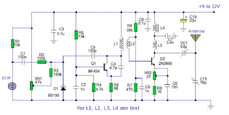
FM Stereo Transmitter
Published:2012/11/23 1:00:00 Author:muriel | Keyword: FM Stereo, Transmitter
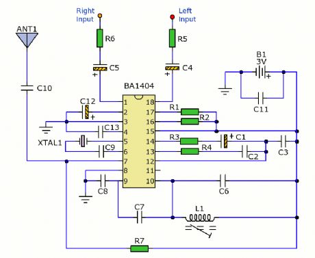
This is a small stereo FM transmitter. Output can be tuned from 88to 108Mhz and the transmitter can be battery powered or be used with the low voltage power supply on this page. (View)
View full Circuit Diagram | Comments | Reading(3172)
MSF Receiver
Published:2012/11/23 0:59:00 Author:muriel | Keyword: MSF Receiver
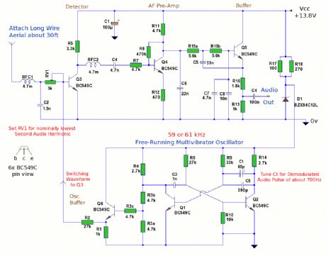
This is an experimental 60khz direct conversion receiver for reception of the UK MSF Time Signal from Anthorn, Cumbria. (The mast array can be seen on the right hand image.) For continued stability, the radio should be continuously supplied from a +13.8v bench power supply.
To achieve enough rf signal pickup, an outside long wire aerial is required, of at least 25 feet anchored to a pole. No aerial balun must be used. (View)
View full Circuit Diagram | Comments | Reading(2171)
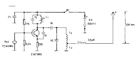
Tracking Transmitter
Published:2012/11/23 0:58:00 Author:muriel | Keyword: Tracking Transmitter
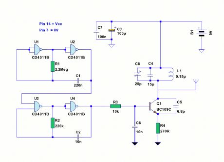
This is a small battery operated Tracking transmitter which broadcasts a repeating radio signal which can be detected by a directional antenna. The transmitter broadcasts an isotropic (radiates in all directions) signal on the FM band. An ordinary FM radio can be used to locate the transmitter, the reception of the signal will improve when the radio antenna is pointed in the direction of the transmitter. (View)
View full Circuit Diagram | Comments | Reading(2216)
Long Range FM Transmitter circuits
Published:2012/11/23 0:58:00 Author:muriel | Keyword: Long Range, FM Transmitter circuits
View full Circuit Diagram | Comments | Reading(1251)
40 Meter Popcorn Superhet Receiver
Published:2012/11/23 0:54:00 Author:muriel | Keyword: 40 Meter, Popcorn Superhet, Receiver
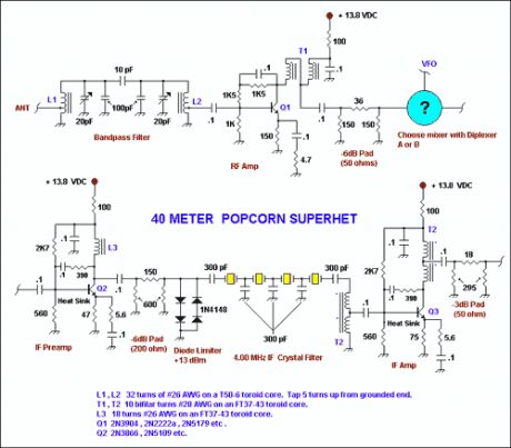
To the right is the schematic for a no-frills, relatively low-cost CW superhet receiver with a 4.00 MHz Intermediate frequency. There is no AGC or RF gain control, however this receiver has good large signal handling capability. This receiver uses just 6 bipolar transistors and an op amp for reasonable volume into headphones. Much of the ideas/design of the various stages must be credited to Wes Hayward as I borrowed heavily from his previous work and through ideas obtained by discussion. If one were to homebrew the diode ring mixers, indeed this would be a very low cost receiver giving reasonable performance which outperforms any NE602 based superhet receivers that I have built or listened to. Below the main schematic is a diplexer diagram that allows the builder to choose from one of two RF and AF diplexers used to terminate the diode ring mixers. (View)
View full Circuit Diagram | Comments | Reading(2170)
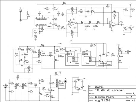
136 kHz direct conversion receiver
Published:2012/11/23 0:54:00 Author:muriel | Keyword: 136 kHz, direct conversion, receiver
1. Introduction
I describe a simple direct conversion receiver, thinked for QRSS and DFCW communications, as companion of ARGO or SPECTRAN programs. I don't pretend to beat the performances of professional or commercial ham radio receiver, the scope is to suggest an easy way for beginner to listen (of course I mean look at) the signals in this poorly populated band. The receiver is useful also as portable receiver, fast turn-on receiver for a quick look an the band or as very low cost (and performances) spectrum analyzer. I currently use this equipment for tests purposes (e.g. visual frequency meter etc.).
2. Circuit description
The front end is described elsewhere prea136.htm The scope is reduce as most as possible the image frequency. I have also tried a different front end, based on a low pass filter with frequency cut-off of 180 kHz. In my QTH I had a lot of undesirables signals on the screen of the PC. The filter is tuned with a signal generator for a bandwidth of 300 Hz, centered on 136.650 kHz. The coupling capacitor between the coils is also tuned for the desired bandwidth. The mixer is the well known NE602. It's not a monster of performances but it provides some gain, it's cheap and easy to find. The rest of audio amplifier is common to other direct conversion receiver. The local oscillator is the original part of my project. The frequency is fixed at 135.500 kHz, so that the image frequency for QRSS portion of the band (137.600 - 137.800 kHz)drop about 4 kHz lower. This permitted to attenuate the image using a simple front end filter. The oscillator is controlled by a 27.100 MHz crystal, the frequency is divided by 200 and the square wave is injected into the mixer. Adjust the trimmer V1 for the best signal to noise ratio (or the best sensitivity). CV1 is tuned for a secure start of oscillations, tune CV2 for the exact frequency of 27.100 MHz. The transformer T1 is winded on an Amidon T50-5 toroidal core. 19 turn primary, 4 turn secondary. There is not an audio amplifier, the output must be connected to the audio board of the computer. If you prefer an audio feedback use an IC amplifier (e.g. an LM386). I usually set-up ARGO offset frequency to read the actual frequency on the screen of the PC. I suggest to use a low noise operational amplifier as U2.
3. Performances
The stability is good since the drifts of the xtal oscillator are divided by 200. The sensitivity is also good since the natural and artificial noise on the band is high. The high selectivity filter in the front end reduce the possibility of overloading of the mixer. In my station the receiver is connected to the antenna through the low pass filter of the transmitter, helping in reducing overload from broadcasting stations. I think that a tuned loop antenna is the optimal companion for this receiver. (View)
View full Circuit Diagram | Comments | Reading(1805)
RC model receivers
Published:2012/11/23 0:53:00 Author:muriel | Keyword: RC model, receivers
View full Circuit Diagram | Comments | Reading(902)
toy car receiver
Published:2012/11/23 0:52:00 Author:muriel | Keyword: toy car , receiver
View full Circuit Diagram | Comments | Reading(1533)
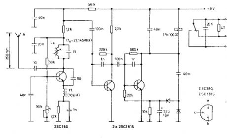
superregenerative receiver
Published:2012/11/23 0:52:00 Author:muriel | Keyword: superregenerative receiver
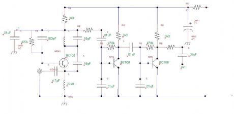
View full Circuit Diagram | Comments | Reading(1281)
| Pages:26/195 At 202122232425262728293031323334353637383940Under 20 |
Circuit Categories
power supply circuit
Amplifier Circuit
Basic Circuit
LED and Light Circuit
Sensor Circuit
Signal Processing
Electrical Equipment Circuit
Control Circuit
Remote Control Circuit
A/D-D/A Converter Circuit
Audio Circuit
Measuring and Test Circuit
Communication Circuit
Computer-Related Circuit
555 Circuit
Automotive Circuit
Repairing Circuit